EP0198512A1 - Mécanisme pour commuter le mode de connection d'opérations dans un appareil d'enregistrement/reproduction magnétique - Google Patents
Mécanisme pour commuter le mode de connection d'opérations dans un appareil d'enregistrement/reproduction magnétique Download PDFInfo
- Publication number
- EP0198512A1 EP0198512A1 EP86105426A EP86105426A EP0198512A1 EP 0198512 A1 EP0198512 A1 EP 0198512A1 EP 86105426 A EP86105426 A EP 86105426A EP 86105426 A EP86105426 A EP 86105426A EP 0198512 A1 EP0198512 A1 EP 0198512A1
- Authority
- EP
- European Patent Office
- Prior art keywords
- ring
- tape
- driving
- operating member
- mode
- Prior art date
- Legal status (The legal status is an assumption and is not a legal conclusion. Google has not performed a legal analysis and makes no representation as to the accuracy of the status listed.)
- Granted
Links
- 238000009877 rendering Methods 0.000 claims 1
- 230000002093 peripheral effect Effects 0.000 abstract description 10
- 238000004804 winding Methods 0.000 abstract description 5
- 230000005540 biological transmission Effects 0.000 description 25
- 230000006835 compression Effects 0.000 description 5
- 238000007906 compression Methods 0.000 description 5
- 238000010276 construction Methods 0.000 description 5
- 230000001360 synchronised effect Effects 0.000 description 2
- 239000002131 composite material Substances 0.000 description 1
Images



Classifications
-
- G—PHYSICS
- G11—INFORMATION STORAGE
- G11B—INFORMATION STORAGE BASED ON RELATIVE MOVEMENT BETWEEN RECORD CARRIER AND TRANSDUCER
- G11B15/00—Driving, starting or stopping record carriers of filamentary or web form; Driving both such record carriers and heads; Guiding such record carriers or containers therefor; Control thereof; Control of operating function
- G11B15/60—Guiding record carrier
- G11B15/66—Threading; Loading; Automatic self-loading
- G11B15/665—Threading; Loading; Automatic self-loading by extracting loop of record carrier from container
- G11B15/6653—Threading; Loading; Automatic self-loading by extracting loop of record carrier from container to pull the record carrier against drum
-
- G—PHYSICS
- G11—INFORMATION STORAGE
- G11B—INFORMATION STORAGE BASED ON RELATIVE MOVEMENT BETWEEN RECORD CARRIER AND TRANSDUCER
- G11B15/00—Driving, starting or stopping record carriers of filamentary or web form; Driving both such record carriers and heads; Guiding such record carriers or containers therefor; Control thereof; Control of operating function
- G11B15/18—Driving; Starting; Stopping; Arrangements for control or regulation thereof
- G11B15/22—Stopping means
Definitions
- the present invention relates to a mechanism in a magnetic recording/reproducing apparatus and, more particularly, to a mechanism for switching the mode of operations suitable for use in a magnetic producing/ reproducing apparatus such as represented by a video cassette recorder.
- a mechanism such as a tape pulling-out guide mechanism, a tape driving mechanism or a braking mechanism is actuated. It is well known to utilize a single power source from which the selected mechanism is commonly driven. As an example of such a driving mechanism, U.S. Patent No. 4,408,236 has been proposed.
- the driving force is transmitted from a single power source to a selected driven member such as the brake, the driving roller through several members such as sliders and arms.
- a selected driven member such as the brake
- the driving roller through several members such as sliders and arms.
- An object of the present invention is, therefore, to provide a mechanism for switching the mode of operations suitable for use in a magnetic recording/ reproducing apparatus which is easy to assemble and accurate in operation, while it can be effectively mode compact.
- the present invention is constructed by driven members which are driven in response to the selected mode of operations, a ring-shaped operating cam formed with a plurality of cam portions corresponding to the respective driven members, and driving means driven by a single power source for rotating the ring-shaped operating cam.
- Position detecting means is provided in the ring-shaped operating cam for detecting the rotational position corresponding to each mode of operation so as to control the rotational position.
- means may further be coupled with the above described power source for commonly driving a tape loading mechanism to form a predetermined feeding passage of a magnetic tape which is drawn out of a cassette.
- each of the plurality of driven members is driven directly by a single ring-shaped operating cam in response to the selected mode of operation, the relative positioning of the respective driven members with respect to the ring-shaped operating cam is facilitated when the same is assembled. Further, the entire construction can be formed in the circular shape, while it is easy to make the size of the entire apparatus compact, because the plurality driven members can be actuated by the single ring-shaped operating cam.
- Fig. 1 shows an embodiment of the mechanism for switching the mode of operations according to the present invention which is applied to a video tape recorder.
- This figure shows the arrangement of various components such as reel supports for engaging with a reels of the cassette tape, a rotary head device and a tape driving mechanism.
- a cassette 100 housing therein reels 102, 103 with a tape 53 wound thereon is loaded on the apparatus as shown by the two dot chain line in the figure.
- Fig. 1 shows the apparatus in the standstill position before the tape is pulled out from the cassette.
- Main portions such as a cylindrical head drum 2 constituting the rotary head device, a capstan 3 for feeding the tape at a constant speed, reel supports 4, 5 with which the reels 102, 103 engage, respectively, a loading ring 6 and a pinch roller 57 are arranged on a disc-shaped chassis 1 as shown in the figure.
- the loading ring 6 is freely rotatably supported on the chassis 1 by means of three holding rollers 10, 11, 12 adapted to shiftably contact with the inner periphery thereof.
- Guide rollers 8, 9 are arranged on the loading ring 6 for drawing the tape out of the cassette cartridge and winding the same around the head drum 2 by a predetermined angle.
- the reel supports 4, 5 are freely rotatably supported on shafts 4-a, 5-a compressively fitted in the chassis 1, respectively.
- a main brake 18 and sub-brakes 19, 20 are arranged near the outer periphery each of the reel supports 4, 5 for simultaneously control the two reel supports.
- brakes are constituted by brake arms 18b-18e, 19b, 20b and brake shoes 18f, 19c, 20c which are rotatably mounted so as to be rotated about pins 14, 15, 16, 17 compressively fitted in the chassis, respectively.
- An idler gear 24 and an arm 25 mounting thereon an intermediate gear 26 are freely rotatably supported between the reel supports 4, 5 so as to be rotated about a shaft 25-b.
- the idler gear 24 is selectively meshed with either one of the reel supports 4, 5 so that the rotational driving force of a capstan motor (refer to Fig. 3) is transmitted to the reel support 4 or 5.
- a band brake 22 having one end thereof securely engaged with a pin 21 on the chassis is wound around the outer periphery of the supply side reel support 5 by a predetermined angle, and the other end of this band brake is rotatably engaged with a pin on a tension arm 23.
- Fig. 2 is an exploded perspective view showing the relationship of the mounting of the loading ring 6, a driving ring 27 and an operating ring 64.
- the loading ring 6 has formed in its entire outer periphery with gear teeth 6g and is arranged on the upper surface of the chassis 1.
- the driving ring 27 has formed in a portion of its inner periphery with gear teeth 27g, and is supported in contact with the lower surface of the chassis 1.
- the operating ring 64 is rotatably supported in the chassis 1 by means of a holder 37 at a position further remote from the chassis 1 with respect to the driving ring 27.
- a plurality of cam surfaces 64a-64f are formed in the inner and outer peripheral surfaces of the operating ring 64 for operating the driven members.
- a groove 64' of a predetermined length is formed in the operating ring 64, and one end of the groove 64' is adapted to engage with a stationary pin 71 secured to the driving ring 27.
- Fig. 3 is a plan view as seen from the rear side of the apparatus shown in Fig. 1.
- the outer peripheral edge of the chassis 1 is formed with a peripheral wall extending in the direction toward the rear side as shown in Fig. 2 so that it provides a guard for the driving ring 27, the operating ring 64 along the entire periphery of the chassis 1.
- a flywheel 28 compressively fitted with an extension of the capstan 3 serves also as a rotor of a direct drive motor of the flat-type for driving the capstan 3.
- a driving force transmission belt 30 is stretched around a driving pulley 28-a compressively fitted with the capstan 3 coaxilly with the flywheel 28 and an intermediate pulley 29 for transmitting the driving force of the reel supports to the idler gear 24.
- Power transmission gear 31 and a driving gear 66 mesh with gear teeth 27b formed in the inner periphery of the driving ring 27.
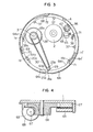
- Fig. 4 is a sectional view showing the positional relationship of the mounting of the driving motor 65, the driving gear 66, the driving ring 27 and the operating ring 64.
- a worm gear 67 is attached to the tip of the driving shaft of the driving motor 65, and it meshes with one of the two gear portions formed in the driving gear 66, and the other gear portion of the driving gear 66 meshes with gear toothed surface of the driving ring 27.
- the driving ring 27 is rotated by the rotation of the driving motor 65 through the driving gear 66.
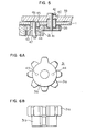
- Fig. 5 is a sectional view showing a first transmission gear 31, a second transmission gear 38 and a third transmission gear 39 for transmitting the driving force of the driving ring 27 to the loading ring 6.
- the third transmission gear 39 meshes with the loading ring 6 on the upper surface of the chassis 1, and is secured by a set screw 42 to one end of a shaft 41 fitted in a bearing 40 which is in turn compressively fitted in the shassis 1.
- the second transmission gear 38 is compressively fitted with the other end of the shaft 41 and the third transmission gear 39 on the upper surface of the chassis and the second transmission gear 38 on the lower surface of the chassis rotate in synchronism with each other.
- the first transmission gear 31 is formed with gear teeth along the entire periphery thereof and is constructed in a composite gear wherein a transmission gear 31a meshing with the driving gear 27 and the second transmission gear 38 is integrally secured by pins 43, 44 to a transmission gear 31b having a single tooth on the outer periphery with the remaining outer periphery being formed as a concentrical cylindrical surface of the same diameter as the dedendum circle of the transmission gear 31a.
- the first transmission gear 31 is rotatably supported by a shaft 46 compressively fitted with a boss 45 which is in turn compressively fitted in the chassis 1.
- the single tooth of the transmission gear 31b located at the lower position is aligned with one of the teeth of the upper transmission gear 31a.
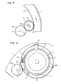
- the guide roller 8 on the loading ring 6 at the inlet side serves to wind the magnetic tape 53 around the inlet side of the head drum 2.
- the central shaft of the guide roller 9 is secured to the upper surface of the loading ring 6 so that the guide roller 9 acts as a tape guide at the inlet side of the head drum 2.
- FIGs. 9A and 9B show the relationship of the driving system for the loading ring 6 and the pinch roller 57.
- a portion each of a guide arm 56 and a pinch roller arm 58 is shown as being broken away so as to show the arrangement of the parts beneath the broken-away portions.
- Fig. 9B is a side view of Fig. 9A.
- the rotation of the loading ring 6 in the direction of the arrow B is converted into the rotation each of the intermediate gear 61 and the arm operating gear 60 in the directions as shown by the arrows in the figure, respectively.
- An arm operating pin 60-a urges a torsion spring 59 in the direction shown by the arrow in the figure.
- the resilient force of the torsion spring 59 caused by the distorsion thereof acts to urge the guide arm 56 in the direction of the arrow C through one end 59-a of the torsion spring 59.
- the guide arm 56 and a guide roller 55 at the outlet side and a winding pin 63 mounted on the guide arm 56 are rotated in the direction of the arrow C.
- a projection 56-a provided on the edge portion of the guide arm 56 acts to rotate the pinch roller arm 58 by the rotation of the guide arm 56 simultaneously therewith in the direction of the arrow C, so that the pinch roller 57 freely rotatably supported on the pinch roller arm 58 is also rotated in the direction of the arrow C.
- the tape 53 is wound onto the head drum 2 at the outlet side.
- the movement each of the above described guide rollers 8, 9 and 55 continues until the guide rollers 8 and 55 reach catchers 13 and 54 shown in Figs. 8 and 9A, respectively.
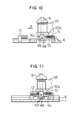
- Fig. 10 is a sectional view showing the positional relationship between the inlet side guide roller 8 and the loading ring 6 during the movement thereof.
- the lower end of the central shaft of the guide roller 8 is formed with a threaded portion and the threaded portion is threadedly engaged with the threaded portion formed in a hole of a boss 48 which slidably engages by a predetermined clearance in an elongated hole 6-a formed in the loading ring 6.
- the securing of the guide roller 8 to the boss 48 is effected by a set screw 49 provided at the side of the boss 48.
- a flange is formed at the lower portion of the boss 48 thereby forming removal preventing means for the boss 48 out of the elongated hole 6-a.
- a receiving plate 50 is compressively fitted onto the outer peripheral surface of the boss 48.
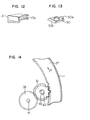
- Fig. 13 is a perspective view schematically showing the configuration of the receiving plate 50.
- a pin 50-a is provided at the rear portion of the receiving plate 50.
- the pin 50-a is adapted to receive a compression spring 51 as shown in Fig. 10 and it is coupled with a projection on the loading ring 6.
- Fig. 11 shows the state of the guide roller 8 shown in Fig. 10 wherein it is moved to abut with its boss 48 against the catcher 13.
- Fig. 12 is a perspective view showing the construction of the catcher 13.
- V-shaped receiving surfaces are formed at the upper and lower side portions of the catcher 13, respectively, which engage with the cylindrical portion of the boss 48 so as to position the guide roller on the plane of the chassis.
- a tapered surface 13b having a predetermined inclination angle with respect to the direction of advance of the loading ring 6 is formed at the lower side of the upper receiving surface of the catcher 13, and the tapered surface 13b is adapted to compressingly engage with a tapered surface 50b formed in the front side of the receiving plate 50.
- a predetermined compressing force is generated between the boss 48 of the guide roller 8 and the V-shaped receiving surfaces of the catcher 13 by virtue of the fact that the compression spring 51 is compressed by a predetermined amount after the guide roller 8 commances contact with the catcher.
- the above described construction of the compressingly contacting portions may be applied to the case of the guide roller 55 at the outlet side and the catcher 54.
- a receiving plate 50c having a tapered surface 50d at the front side thereof is provided at the lower side of the guide roller 55 above the guide arm 56 as shown in Figs. 9A, 9B.
- the outlet side guide roller 55 is compressingly contacted with the catcher 54 by the resilient compressing force of the torsion spring 59 instead of the compression spring 51.
- the timed relationship between the compressing contacts of the guide rollers 8, 55 with the respective catchers 13, 54 is set to be synchronized with each other by adjusting the operating phases of the loading ring 6 and the meshing of the intermittent gear 61 with the arm operating gear 60.
- the operation of the driving ring when these guide rollers are compressingly contacted with the respective catchers by the predetermined forces, respectively, will be described below.
- Fig. 14 shows the positional relationship between the driving ring 27 and the first transmission gear 31 at the time point the amount of compression of the compression spring 51 reaches a predetermined amount.
- a half of the gear toothed portion of the driving ring 27 at the end thereof in the direction of thickness of the gear toothed portion at the side of the chasses is relieved from the toothed surface of the transmission gear 31a so that no meshing engagement with each other in these portions will take place.
- only a single tooth surface of the transmission gear 31b will mesh with the last gear toothed surface of the driving ring 27.
- the inner peripheral surface of the driving ring 27 continues to be held under the condition under which the inner peripheral surface of the driving ring 27 leaves the single toothed surface of the transmission gear 31b in the pushed-in position by a predetermined amount.
- the timing of this pushed-in position is set to be synchronized with the timing at which the predetermined compressing contact force is generated between the guide roller and the catcher by adjusting the relationship between the operational phases of the gears.
- the pin 71 secured onto the driving ring 27 will move into the interior of the groove 64' formed in the operating ring 64 in the direction of the arrow A by virtue of the fact that the driving ring 27 is driven in the direction of the arrow A in Fig. 3 during the actuation of the loading ring.
- the operating ring 64 is maintained in its standstill state by the tension of a tension spring 69.
- the pin 71 on the driving ring 27 reaches the point 71 1 at the end of
- a slide switch 68 is secured to the interior of the outer peripheral edge of the chassis 1, and the actuating portion of the switch 68 engages with a pin 72 provided on the operating ring 64 so that the mode of operation is detected according to the respective rotational angle of the operating ring 64.
- the cam surfaces 64a-64f formed independently from each other in the inner and outer peripheral surfaces of the operating ring 64 rotate also in response to the actuation of the driving ring 27.
- cam surfaces 64a-64f which are configured so as to correspond to the modes of operations detected by the above described slide switch 68. Further various operations such as the recording/ reproducing, the fast formed winding and the rewinding are effected by electrically controlling the head drum 2, the capstan 3 for selectively rotating them in response to the mode of operation detected by the slide switch 68.
Landscapes
- Transmission Devices (AREA)
- Recording Or Reproducing By Magnetic Means (AREA)
- Gear Transmission (AREA)
Applications Claiming Priority (2)
| Application Number | Priority Date | Filing Date | Title |
|---|---|---|---|
| JP60082434A JPS61242364A (ja) | 1985-04-19 | 1985-04-19 | 記録再生装置の駆動力伝達機構 |
| JP82434/85 | 1985-04-19 |
Publications (2)
| Publication Number | Publication Date |
|---|---|
| EP0198512A1 true EP0198512A1 (fr) | 1986-10-22 |
| EP0198512B1 EP0198512B1 (fr) | 1990-08-01 |
Family
ID=13774451
Family Applications (1)
| Application Number | Title | Priority Date | Filing Date |
|---|---|---|---|
| EP86105426A Expired EP0198512B1 (fr) | 1985-04-19 | 1986-04-18 | Mécanisme pour commuter le mode de connection d'opérations dans un appareil d'enregistrement/reproduction magnétique |
Country Status (4)
| Country | Link |
|---|---|
| US (2) | US4748521A (fr) |
| EP (1) | EP0198512B1 (fr) |
| JP (1) | JPS61242364A (fr) |
| DE (1) | DE3673052D1 (fr) |
Cited By (6)
| Publication number | Priority date | Publication date | Assignee | Title |
|---|---|---|---|---|
| GB2190533A (en) * | 1986-05-14 | 1987-11-18 | Samsung Electronics Co Ltd | Tape player/recorder |
| GB2205677A (en) * | 1987-05-30 | 1988-12-14 | Tanashin Denki Co | Pinch roller driving device for a tape feeding device |
| EP0222111B1 (fr) * | 1985-11-15 | 1990-05-16 | GRUNDIG E.M.V. Elektro-Mechanische Versuchsanstalt Max Grundig holländ. Stiftung & Co. KG. | Appareil vidéo à bande magnétique |
| US4985788A (en) * | 1987-10-21 | 1991-01-15 | Hitachi Video Engineering Inc. | Recording and reproducing apparatus |
| EP0381081A3 (fr) * | 1989-01-31 | 1991-10-23 | Kabushiki Kaisha Toshiba | Dispositif anti-mou pour bande de cassette pour usage dans un appareil d'enregistrement et de reproduction magnétique |
| EP0632440A3 (fr) * | 1993-05-21 | 1995-06-07 | Sanyo Electric Co | Appareil d'enregistrement/reproduction magnétique. |
Families Citing this family (10)
| Publication number | Priority date | Publication date | Assignee | Title |
|---|---|---|---|---|
| US4873591A (en) * | 1986-08-28 | 1989-10-10 | Canon Kabushiki Kaisha | Tape loading device having pair of tape guide post units on pair of rotatable members |
| JPH02210647A (ja) * | 1989-02-10 | 1990-08-22 | Hitachi Ltd | 磁気記録再生装置 |
| US5140475A (en) * | 1989-12-14 | 1992-08-18 | Tanashin Denki Co., Ltd. | Tape recorder with automatic pre-reproduction tape slack eliminating function |
| JPH05342834A (ja) * | 1992-06-15 | 1993-12-24 | Hitachi Ltd | 磁気記録再生装置及びその操作方法 |
| JP3273637B2 (ja) * | 1992-07-10 | 2002-04-08 | 東北パイオニア株式会社 | 記録再生装置用モード切換え機構 |
| US5515182A (en) * | 1992-08-31 | 1996-05-07 | Howtek, Inc. | Rotary scanner |
| US5349485A (en) * | 1992-09-30 | 1994-09-20 | Industrial Technology Research Institute | Magnetic tape loading mechanism for a magnetic recording and/or reproducing apparatus |
| KR100195072B1 (ko) * | 1993-02-26 | 1999-06-15 | 윤종용 | 정보 기록 및 재생 시스템 |
| CN101819793B (zh) * | 2004-11-18 | 2012-09-05 | 日本电产三协株式会社 | 磁信息媒体记录再生装置 |
| JP4689245B2 (ja) * | 2004-11-18 | 2011-05-25 | 日本電産サンキョー株式会社 | 磁気情報媒体記録再生装置 |
Citations (5)
| Publication number | Priority date | Publication date | Assignee | Title |
|---|---|---|---|---|
| EP0087952A2 (fr) * | 1982-02-25 | 1983-09-07 | Matsushita Electric Industrial Co., Ltd. | Appareil d'enregistrement et/ou de reproduction à bande magnétique |
| US4408236A (en) * | 1980-02-08 | 1983-10-04 | Matsushita Electric Industrial Co., Ltd. | Magnetic tape recording and/or reproducing apparatus |
| EP0115075A1 (fr) * | 1982-12-28 | 1984-08-08 | Olympus Optical Co., Ltd. | Appareil d'enregistrement et/ou de reproduction magnétique |
| DE3406887A1 (de) * | 1983-02-28 | 1984-08-30 | Victor Company Of Japan, Ltd., Yokohama, Kanagawa | Aufzeichnungs- und/oder wiedergabegeraet nach einem automatischen bandladetyp |
| DE3412527A1 (de) * | 1983-04-08 | 1984-10-18 | Victor Company Of Japan, Ltd., Yokohama, Kanagawa | Aufzeichnungs- und/oder wiedergabegeraet mit automatischer magnetbandladung |
Family Cites Families (3)
| Publication number | Priority date | Publication date | Assignee | Title |
|---|---|---|---|---|
| JPS5774859A (en) * | 1980-10-24 | 1982-05-11 | Matsushita Electric Ind Co Ltd | Magnetic recording and reproducing device |
| US4491885A (en) * | 1981-02-06 | 1985-01-01 | Matsushita Electric Industrial Co., Ltd. | Magnetic recording/playback device |
| JPS5963051A (ja) * | 1982-10-01 | 1984-04-10 | Hitachi Ltd | 磁気記録再生装置 |
-
1985
- 1985-04-19 JP JP60082434A patent/JPS61242364A/ja active Granted
-
1986
- 1986-04-18 DE DE8686105426T patent/DE3673052D1/de not_active Expired - Lifetime
- 1986-04-18 EP EP86105426A patent/EP0198512B1/fr not_active Expired
- 1986-04-21 US US06/854,031 patent/US4748521A/en not_active Ceased
-
1990
- 1990-05-31 US US07/531,084 patent/USRE33784E/en not_active Expired - Lifetime
Patent Citations (5)
| Publication number | Priority date | Publication date | Assignee | Title |
|---|---|---|---|---|
| US4408236A (en) * | 1980-02-08 | 1983-10-04 | Matsushita Electric Industrial Co., Ltd. | Magnetic tape recording and/or reproducing apparatus |
| EP0087952A2 (fr) * | 1982-02-25 | 1983-09-07 | Matsushita Electric Industrial Co., Ltd. | Appareil d'enregistrement et/ou de reproduction à bande magnétique |
| EP0115075A1 (fr) * | 1982-12-28 | 1984-08-08 | Olympus Optical Co., Ltd. | Appareil d'enregistrement et/ou de reproduction magnétique |
| DE3406887A1 (de) * | 1983-02-28 | 1984-08-30 | Victor Company Of Japan, Ltd., Yokohama, Kanagawa | Aufzeichnungs- und/oder wiedergabegeraet nach einem automatischen bandladetyp |
| DE3412527A1 (de) * | 1983-04-08 | 1984-10-18 | Victor Company Of Japan, Ltd., Yokohama, Kanagawa | Aufzeichnungs- und/oder wiedergabegeraet mit automatischer magnetbandladung |
Cited By (8)
| Publication number | Priority date | Publication date | Assignee | Title |
|---|---|---|---|---|
| EP0222111B1 (fr) * | 1985-11-15 | 1990-05-16 | GRUNDIG E.M.V. Elektro-Mechanische Versuchsanstalt Max Grundig holländ. Stiftung & Co. KG. | Appareil vidéo à bande magnétique |
| GB2190533A (en) * | 1986-05-14 | 1987-11-18 | Samsung Electronics Co Ltd | Tape player/recorder |
| GB2190533B (en) * | 1986-05-14 | 1990-06-13 | Samsung Electronics Co Ltd | Tape player/recorder |
| GB2205677A (en) * | 1987-05-30 | 1988-12-14 | Tanashin Denki Co | Pinch roller driving device for a tape feeding device |
| GB2205677B (en) * | 1987-05-30 | 1991-01-16 | Tanashin Denki Co | Pinch roller driving device for a tape feeding device |
| US4985788A (en) * | 1987-10-21 | 1991-01-15 | Hitachi Video Engineering Inc. | Recording and reproducing apparatus |
| EP0381081A3 (fr) * | 1989-01-31 | 1991-10-23 | Kabushiki Kaisha Toshiba | Dispositif anti-mou pour bande de cassette pour usage dans un appareil d'enregistrement et de reproduction magnétique |
| EP0632440A3 (fr) * | 1993-05-21 | 1995-06-07 | Sanyo Electric Co | Appareil d'enregistrement/reproduction magnétique. |
Also Published As
| Publication number | Publication date |
|---|---|
| JPS61242364A (ja) | 1986-10-28 |
| DE3673052D1 (de) | 1990-09-06 |
| US4748521A (en) | 1988-05-31 |
| USRE33784E (en) | 1991-12-31 |
| EP0198512B1 (fr) | 1990-08-01 |
| JPH0461419B2 (fr) | 1992-09-30 |
Similar Documents
| Publication | Publication Date | Title |
|---|---|---|
| EP0198512A1 (fr) | Mécanisme pour commuter le mode de connection d'opérations dans un appareil d'enregistrement/reproduction magnétique | |
| US4661864A (en) | Magnetic recording and reproducing apparatus | |
| JPS61199260A (ja) | 記録および/または再生装置 | |
| JPS5927984B2 (ja) | 磁気テ−プ装置 | |
| JPS59217020A (ja) | 一方クラツチ装置 | |
| US4404606A (en) | Automatic music selecting device for tape recorder | |
| US4114831A (en) | Concentric reel drive for a tape cassette | |
| JPS6059651B2 (ja) | 可動テ−プガイド装置 | |
| JPS6341143B2 (fr) | ||
| JPH0438058B2 (fr) | ||
| JPH0461420B2 (fr) | ||
| EP0198941B1 (fr) | Appareil d'enregistrement et de reproduction magnétique | |
| KR870000442Y1 (ko) | 비디오 테이프 레코오더의 테이프 텐션 조절장치 | |
| JPS5946065B2 (ja) | 磁気記録再生装置 | |
| JPH0248993Y2 (fr) | ||
| JP2603906B2 (ja) | 記録再生装置 | |
| US5862027A (en) | Cam gear driving apparatus of a video cassette recorder | |
| JPH0210503B2 (fr) | ||
| JP2633985B2 (ja) | 磁気記録再生装置 | |
| JPH0461421B2 (fr) | ||
| JPH039547B2 (fr) | ||
| JPS6151654A (ja) | 磁気記録再生装置 | |
| JPH0522978B2 (fr) | ||
| JPS6152539B2 (fr) | ||
| JPH0687329B2 (ja) | 磁気記録再生装置 |
Legal Events
| Date | Code | Title | Description |
|---|---|---|---|
| PUAI | Public reference made under article 153(3) epc to a published international application that has entered the european phase |
Free format text: ORIGINAL CODE: 0009012 |
|
| 17P | Request for examination filed |
Effective date: 19860418 |
|
| AK | Designated contracting states |
Kind code of ref document: A1 Designated state(s): DE FR GB |
|
| 17Q | First examination report despatched |
Effective date: 19881107 |
|
| GRAA | (expected) grant |
Free format text: ORIGINAL CODE: 0009210 |
|
| AK | Designated contracting states |
Kind code of ref document: B1 Designated state(s): DE FR GB |
|
| PG25 | Lapsed in a contracting state [announced via postgrant information from national office to epo] |
Ref country code: FR Effective date: 19900801 |
|
| REF | Corresponds to: |
Ref document number: 3673052 Country of ref document: DE Date of ref document: 19900906 |
|
| EN | Fr: translation not filed | ||
| PG25 | Lapsed in a contracting state [announced via postgrant information from national office to epo] |
Ref country code: GB Effective date: 19910418 |
|
| PLBE | No opposition filed within time limit |
Free format text: ORIGINAL CODE: 0009261 |
|
| STAA | Information on the status of an ep patent application or granted ep patent |
Free format text: STATUS: NO OPPOSITION FILED WITHIN TIME LIMIT |
|
| 26N | No opposition filed | ||
| GBPC | Gb: european patent ceased through non-payment of renewal fee | ||
| PGFP | Annual fee paid to national office [announced via postgrant information from national office to epo] |
Ref country code: DE Payment date: 20050609 Year of fee payment: 20 |