EP0198526A2 - Diviseur de puissance à couches minces - Google Patents
Diviseur de puissance à couches minces Download PDFInfo
- Publication number
- EP0198526A2 EP0198526A2 EP86200414A EP86200414A EP0198526A2 EP 0198526 A2 EP0198526 A2 EP 0198526A2 EP 86200414 A EP86200414 A EP 86200414A EP 86200414 A EP86200414 A EP 86200414A EP 0198526 A2 EP0198526 A2 EP 0198526A2
- Authority
- EP
- European Patent Office
- Prior art keywords
- thin film
- power coupler
- film power
- coupler according
- inductor
- Prior art date
- Legal status (The legal status is an assumption and is not a legal conclusion. Google has not performed a legal analysis and makes no representation as to the accuracy of the status listed.)
- Withdrawn
Links
Images

Classifications
-
- H—ELECTRICITY
- H03—ELECTRONIC CIRCUITRY
- H03H—IMPEDANCE NETWORKS, e.g. RESONANT CIRCUITS; RESONATORS
- H03H1/00—Constructional details of impedance networks whose electrical mode of operation is not specified or applicable to more than one type of network
-
- H—ELECTRICITY
- H03—ELECTRONIC CIRCUITRY
- H03H—IMPEDANCE NETWORKS, e.g. RESONANT CIRCUITS; RESONATORS
- H03H7/00—Multiple-port networks comprising only passive electrical elements as network components
- H03H7/48—Networks for connecting several sources or loads, working on the same frequency or frequency band, to a common load or source
Definitions
- the present invention relates to a thin film power coupler with lumped circuit elements, comprising inductors and capacitors.
- microstrip line power couplers can be achieved by thin film technology.
- the dimensions of such circuits are related with the central working frequency and they increase when decreasing the frequency. For intermediate frequencies, about 70 to 140 MHz, those dimensions become unallowable, then circuits with lumped elements are necessary.
- the power couplers achieved by discrete circuit elements generally have good performance, but they are very expensive and above all they cause problems in connecting them with the other parts of the circuit, when the latter has been achieved by thin film technology.
- the power couplers achieved by thin film technology and lumped circuit elements instead' occupy a lot of space and have inadequate performance, compelling to use the devices in a very narrow band about the central working frequency or in very unbalanced operations.
- the present invention refers to a thin film power coupler with lumped circuit elements, comprising inductors and capacitors characterized in that at least a first and a second inductor are magnetically coupled to each other.
- FIG. 1 we notice four ports 1, 2, 3 and 4.
- a capacitor 5 is connected between the ports 1 and 2, while a capacitor 6 is connected between the ports 3 and 4.
- a terminal of an inductor 7 is also connected to the port 1, while a terminal of an inductor 8 is also connected to the port 2.
- a terminal of an inductor 9 is also connected to the port 3, while a terminal of an inductor 10 is also connected to the port 4.
- the other two terminals of the inductors 7 and 9 are connected to each other, forming a first branch of the circuit, to a terminal of a capacitor 11 and to a terminal of a capacitor 12.
- the other two terminals of the inductors 8 and 10 are connected to each other, forming a second branch of the circuit, to the other terminal of the capacitor 11 and to a termi nal of a capacitor 13.
- the other two terminals of the capacitors 12 and 13 are put to a ground 14.
- the capcitors 5 and 6 have the same value and the capacitors 12 and 13 have the same value . too.
- the four inductors 7, 8, 9 and 10 also have the same value, moreover, the inductors 7 and 8 are coupled to each other by mutual inductance, the same as it happens for the inductors 9 and 10.
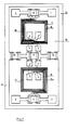
- FIG. 2 in which the same components of Fig. 1 are indicated with the same numbers, are described only the essential elements to the understanding of the present invention.
- the four inductors 7, 8, 9 and 10 are obtained on a first surface of an insulating support 15 with the thin film technology.
- the inductors 7 and 8 are gained by using two microstrip lines facing each other, forming a square shaped spiral 16 and in this way they are magnetically coupled to each other.
- the inductors 9 and 10 are also gained by using two microstrip lines facing each other, forming a square shaped spiral 17 and in this way they are also magnetically coupled to each other too.
- the second surface of the support 15, not shown in the Figure is lacking in ground layer to avoid the effects of the unwanted capacitance of the same inductors.
- This achievement is a particular advantage in that it allows a very good magnetic coupling for each of the two inductors pairs 7-8 and 9-10 and a very good space utilization.
- adopting the square shape we obtain a ratio between the inductance value and the surface taken up much higher compared with circular or elliptic shapes.
- two inductors in a surface normally taken up by only one inductor with a considerable space saving.
- the spiral can be gained by using a circular shape and in a second change with an elliptic shape.
- the component dimensioning has been carried out to obtain a 3 dB and 90° power divider working with 70 MHz central frequency in such a way that in the 50-90 MHz frequency band it works in maximum 1 dB unbalanced operation.
- the power divider parameters can vary between the following values: “1” from 5 to 10 mm; “w” from 0.05 to 0.2 mm; “s” from 0.01 to 0.1 mm; “D” from 0.1 to 0.5 mm and “N” from 2 to 5.
- the operation of the device is that well known of a 3 dB and 90° power divider, in which by matching conditions the input signal comes to the port 1, a half of the input signal comes out from the port 2, called “coupled port”, a half of the input signal comes out from the port 3 called “direct port” and no signal comes out from the port 4, called “insulated port”. Moreover, the signals coming out from the ports 2 and 3 are 90° out of phase with each other.
- the capacitor 11 allows to improve the electric coupling between the first and the second branch of the power divider and to recover possible tolerances incurred by manufacturing the thin film inductors.
- the thin film power coupler object of the present invention, are clear. In particular they result in that such coupler has been achieved by thin film technology, it is integrated on the same support with the remaining circuit, it is reliable, it is not very expensive, it takes up little space, it has very good performance and it can be used either as power divider or as power adder.
Landscapes
- Microwave Amplifiers (AREA)
- Photovoltaic Devices (AREA)
- Organic Insulating Materials (AREA)
- Near-Field Transmission Systems (AREA)
- Waveguides (AREA)
- Coupling Device And Connection With Printed Circuit (AREA)
- Piezo-Electric Or Mechanical Vibrators, Or Delay Or Filter Circuits (AREA)
- Parts Printed On Printed Circuit Boards (AREA)
- Coils Or Transformers For Communication (AREA)
Applications Claiming Priority (2)
| Application Number | Priority Date | Filing Date | Title |
|---|---|---|---|
| IT20197/85A IT1183558B (it) | 1985-04-02 | 1985-04-02 | Accoppiatore di potenza in film sottile |
| IT2019785 | 1985-04-02 |
Publications (2)
| Publication Number | Publication Date |
|---|---|
| EP0198526A2 true EP0198526A2 (fr) | 1986-10-22 |
| EP0198526A3 EP0198526A3 (fr) | 1988-06-01 |
Family
ID=11164640
Family Applications (1)
| Application Number | Title | Priority Date | Filing Date |
|---|---|---|---|
| EP86200414A Withdrawn EP0198526A3 (fr) | 1985-04-02 | 1986-03-17 | Diviseur de puissance à couches minces |
Country Status (8)
| Country | Link |
|---|---|
| US (1) | US4777458A (fr) |
| EP (1) | EP0198526A3 (fr) |
| JP (1) | JPS61230510A (fr) |
| CN (1) | CN86102168A (fr) |
| AU (1) | AU588291B2 (fr) |
| IT (1) | IT1183558B (fr) |
| NO (1) | NO861089L (fr) |
| ZA (1) | ZA862337B (fr) |
Cited By (1)
| Publication number | Priority date | Publication date | Assignee | Title |
|---|---|---|---|---|
| EP0298434A3 (fr) * | 1987-07-08 | 1990-05-02 | Siemens Aktiengesellschaft | Coupleur en quadrature selon la technique des couches minces |
Families Citing this family (22)
| Publication number | Priority date | Publication date | Assignee | Title |
|---|---|---|---|---|
| JPH01122606U (fr) * | 1988-02-15 | 1989-08-21 | ||
| US5469129A (en) * | 1994-08-29 | 1995-11-21 | Motorola, Inc. | Impedance transforming three-port power divider/combiner using lumped elements |
| US5748056A (en) * | 1996-10-02 | 1998-05-05 | Itt Industries, Inc. | Compact 90° monolithic GaAs coupler for wireless applications |
| KR100223375B1 (ko) * | 1997-06-11 | 1999-10-15 | 윤종용 | 마이크로웨이브 시스템에 사용하기 위한 주파수변환기 |
| JP3257487B2 (ja) * | 1997-12-05 | 2002-02-18 | 株式会社村田製作所 | 方向性結合器 |
| US6765455B1 (en) * | 2000-11-09 | 2004-07-20 | Merrimac Industries, Inc. | Multi-layered spiral couplers on a fluropolymer composite substrate |
| US6639490B2 (en) | 2001-10-31 | 2003-10-28 | International Business Machines Corporation | Ninety degree coupler for radio frequency degraded circuits |
| US7190240B2 (en) * | 2003-06-25 | 2007-03-13 | Werlatone, Inc. | Multi-section coupler assembly |
| US6972639B2 (en) | 2003-12-08 | 2005-12-06 | Werlatone, Inc. | Bi-level coupler |
| US7245192B2 (en) * | 2003-12-08 | 2007-07-17 | Werlatone, Inc. | Coupler with edge and broadside coupled sections |
| US7119633B2 (en) * | 2004-08-24 | 2006-10-10 | Endwave Corporation | Compensated interdigitated coupler |
| US7561007B1 (en) * | 2006-08-02 | 2009-07-14 | Lockheed Martin Corporation | Switchable phase shifter for providing selectable phase shift paths |
| GB2487019B (en) * | 2007-05-08 | 2012-08-15 | Scanimetrics Inc | Ultra high speed signal transmission/reception |
| DE102011080429A1 (de) | 2011-08-04 | 2013-02-07 | Endress + Hauser Gmbh + Co. Kg | Galvanisch getrennter Richtkoppler |
| US9888568B2 (en) | 2012-02-08 | 2018-02-06 | Crane Electronics, Inc. | Multilayer electronics assembly and method for embedding electrical circuit components within a three dimensional module |
| CN103904405B (zh) * | 2014-04-08 | 2016-11-09 | 烟台永利电器有限公司 | 一种具有长方形分离杆双环3dB电桥的同频合路器 |
| US9230726B1 (en) | 2015-02-20 | 2016-01-05 | Crane Electronics, Inc. | Transformer-based power converters with 3D printed microchannel heat sink |
| US9628032B1 (en) * | 2015-12-11 | 2017-04-18 | Infineon Technologies Ag | RF device package with integrated hybrid coupler |
| KR101777716B1 (ko) * | 2016-08-04 | 2017-09-18 | 자화전자(주) | 회로기판 및 이를 포함하는 진동 발생장치 |
| WO2020185560A1 (fr) * | 2019-03-13 | 2020-09-17 | Avx Corporation | Coupleur compact à film mince pouvant être monté en surface ayant une performance à large bande |
| CN113224492B (zh) * | 2021-04-19 | 2021-12-28 | 中国电子科技集团公司第二十九研究所 | 一种基于互感耦合的超宽带功分器芯片 |
| CN113224045B (zh) * | 2021-04-19 | 2022-04-29 | 中国电子科技集团公司第二十九研究所 | 一种基于折叠线圈的紧凑功分器芯片 |
Family Cites Families (13)
| Publication number | Priority date | Publication date | Assignee | Title |
|---|---|---|---|---|
| US3452300A (en) * | 1965-08-11 | 1969-06-24 | Merrimac Research & Dev Inc | Four port directive coupler having electrical symmetry with respect to both axes |
| US3484724A (en) * | 1968-08-16 | 1969-12-16 | Adams Russel Co Inc | Transmission line quadrature coupler |
| US3593208A (en) * | 1969-03-17 | 1971-07-13 | Bell Telephone Labor Inc | Microwave quadrature coupler having lumped-element capacitors |
| US3723914A (en) * | 1972-01-26 | 1973-03-27 | J Cappucci | Lumped constant quadrature coupler with improved parasitic suppression |
| US3869585A (en) * | 1972-12-19 | 1975-03-04 | Lorch Electronics Corp | Asymmetric quadrature hybrid couplers |
| DD109127A1 (fr) * | 1973-12-21 | 1974-10-12 | ||
| US3999150A (en) * | 1974-12-23 | 1976-12-21 | International Business Machines Corporation | Miniaturized strip-line directional coupler package having spirally wound coupling lines |
| US4143379A (en) * | 1977-07-14 | 1979-03-06 | Hazeltine Corporation | Antenna system having modular coupling network |
| JPS5451445A (en) * | 1977-09-30 | 1979-04-23 | Fujitsu Ltd | Directional coupler |
| US4216446A (en) * | 1978-08-28 | 1980-08-05 | Motorola, Inc. | Quarter wave microstrip directional coupler having improved directivity |
| JPS5625817A (en) * | 1979-08-08 | 1981-03-12 | Mitsubishi Electric Corp | Directional coupler |
| FR2523374A1 (fr) * | 1982-03-12 | 1983-09-16 | Labo Electronique Physique | Additionneur-diviseur de puissance a large bande pour circuit hyperfrequence et transformateur d'impedance realise a partir de cet additionneur-diviseur |
| IT1177093B (it) * | 1984-10-30 | 1987-08-26 | Gte Communication Syst | Perfezionamenti agli accoppiatori direzionali del tipo branchline |
-
1985
- 1985-04-02 IT IT20197/85A patent/IT1183558B/it active
-
1986
- 1986-03-14 AU AU54849/86A patent/AU588291B2/en not_active Ceased
- 1986-03-17 EP EP86200414A patent/EP0198526A3/fr not_active Withdrawn
- 1986-03-20 NO NO861089A patent/NO861089L/no unknown
- 1986-03-27 ZA ZA862337A patent/ZA862337B/xx unknown
- 1986-03-31 US US06/846,773 patent/US4777458A/en not_active Expired - Fee Related
- 1986-03-31 CN CN198686102168A patent/CN86102168A/zh active Pending
- 1986-04-01 JP JP61072629A patent/JPS61230510A/ja active Pending
Cited By (1)
| Publication number | Priority date | Publication date | Assignee | Title |
|---|---|---|---|---|
| EP0298434A3 (fr) * | 1987-07-08 | 1990-05-02 | Siemens Aktiengesellschaft | Coupleur en quadrature selon la technique des couches minces |
Also Published As
| Publication number | Publication date |
|---|---|
| ZA862337B (en) | 1986-11-26 |
| NO861089L (no) | 1986-10-03 |
| CN86102168A (zh) | 1986-10-01 |
| AU5484986A (en) | 1986-10-09 |
| IT8520197A0 (it) | 1985-04-02 |
| IT1183558B (it) | 1987-10-22 |
| AU588291B2 (en) | 1989-09-14 |
| EP0198526A3 (fr) | 1988-06-01 |
| JPS61230510A (ja) | 1986-10-14 |
| US4777458A (en) | 1988-10-11 |
Similar Documents
| Publication | Publication Date | Title |
|---|---|---|
| US4777458A (en) | Thin film power coupler | |
| US4125810A (en) | Broadband high frequency baluns and mixer | |
| US5515015A (en) | Transceiver duplex filter utilizing saw filter | |
| EP0419756A2 (fr) | Transformateur imprimé | |
| US5164687A (en) | Compact lumped constant non-reciprocal circuit element | |
| US6246299B1 (en) | High power broadband combiner having ferrite cores | |
| US6850127B2 (en) | Laminated electronic component | |
| JPH06283904A (ja) | 誘電体フィルタおよびこれを用いた分波器 | |
| US3223947A (en) | Broadband single pole multi-throw diode switch with filter providing matched path between input and on port | |
| US10998876B2 (en) | Balun | |
| US3882432A (en) | RF broadband transmission line impedance matching transformer pair for less than 4 to 1 impedance transformations | |
| JPH0234001A (ja) | 帯域阻止フイルタ | |
| JP2003087074A (ja) | 積層型フィルタ | |
| CN220172349U (zh) | 巴伦以及射频前端模组 | |
| US12334620B2 (en) | Marchand balun formed in a laminated substrate and including main lines and sub-lines formed by partial lines having specified distance relationships | |
| US12388162B2 (en) | Marchand balun formed in a laminated substrate and including a main line and sub-lines, where a parallel line is connected to a sub-line | |
| US6509810B2 (en) | Filter, duplexer, and communication device | |
| US3895320A (en) | Broad-band lumped-element circulator | |
| US6369668B1 (en) | Duplexer and communication apparatus including the same | |
| JPH1065467A (ja) | フィルタ付き低雑音増幅器 | |
| JP4195568B2 (ja) | 積層型電子部品 | |
| JP3405286B2 (ja) | 誘電体フィルタとそれを用いた歪み補償型増幅器 | |
| JP3230588B2 (ja) | 非可逆回路素子 | |
| US12230859B2 (en) | Balun | |
| US5959509A (en) | Printed 180 degree differential phase shifter including a non-uniform non-regular line |
Legal Events
| Date | Code | Title | Description |
|---|---|---|---|
| PUAI | Public reference made under article 153(3) epc to a published international application that has entered the european phase |
Free format text: ORIGINAL CODE: 0009012 |
|
| AK | Designated contracting states |
Kind code of ref document: A2 Designated state(s): BE DE FR GB IT NL SE |
|
| RIN1 | Information on inventor provided before grant (corrected) |
Inventor name: PARDINI, ROSSANO |
|
| PUAL | Search report despatched |
Free format text: ORIGINAL CODE: 0009013 |
|
| AK | Designated contracting states |
Kind code of ref document: A3 Designated state(s): BE DE FR GB IT NL SE |
|
| RAP1 | Party data changed (applicant data changed or rights of an application transferred) |
Owner name: SIEMENS TELECOMUNICAZIONI S.P.A. |
|
| STAA | Information on the status of an ep patent application or granted ep patent |
Free format text: STATUS: THE APPLICATION IS DEEMED TO BE WITHDRAWN |
|
| 18D | Application deemed to be withdrawn |
Effective date: 19881202 |
|
| RIN1 | Information on inventor provided before grant (corrected) |
Inventor name: PARDINI, ROSSANO |