EP0198578A1 - Antenne sinueuse à double polarisation - Google Patents
Antenne sinueuse à double polarisation Download PDFInfo
- Publication number
- EP0198578A1 EP0198578A1 EP86301175A EP86301175A EP0198578A1 EP 0198578 A1 EP0198578 A1 EP 0198578A1 EP 86301175 A EP86301175 A EP 86301175A EP 86301175 A EP86301175 A EP 86301175A EP 0198578 A1 EP0198578 A1 EP 0198578A1
- Authority
- EP
- European Patent Office
- Prior art keywords
- sinuous
- antenna
- cell
- arms
- arm
- Prior art date
- Legal status (The legal status is an assumption and is not a legal conclusion. Google has not performed a legal analysis and makes no representation as to the accuracy of the status listed.)
- Granted
Links
Images




Classifications
-
- H—ELECTRICITY
- H01—ELECTRIC ELEMENTS
- H01Q—ANTENNAS, i.e. RADIO AERIALS
- H01Q9/00—Electrically-short antennas having dimensions not more than twice the operating wavelength and consisting of conductive active radiating elements
- H01Q9/04—Resonant antennas
- H01Q9/16—Resonant antennas with feed intermediate between the extremities of the antenna, e.g. centre-fed dipole
- H01Q9/26—Resonant antennas with feed intermediate between the extremities of the antenna, e.g. centre-fed dipole with folded element or elements, the folded parts being spaced apart a small fraction of operating wavelength
- H01Q9/27—Spiral antennas
-
- H—ELECTRICITY
- H01—ELECTRIC ELEMENTS
- H01Q—ANTENNAS, i.e. RADIO AERIALS
- H01Q11/00—Electrically-long antennas having dimensions more than twice the shortest operating wavelength and consisting of conductive active radiating elements
- H01Q11/02—Non-resonant antennas, e.g. travelling-wave antenna
- H01Q11/10—Logperiodic antennas
Definitions
- This invention relates to wide bandwidth sinuous antennas with two orthogonal senses of polarization and particularly to sinuous antennas with both senses of circular polarizations, and more particularly to dual circularly polarized sinuous antennas with pattern, gain, impedance and bandwidth properties similar to the singly circularly polarized Archimedes and log-spiral antennas.
- the American Heritage Dictionary defines the adjective sinuous as"characterized by many curves or turns; winding.” Sinuous as used herein is generalized to characterize lines consisting of curves or curves and sharp turns or bends, or straight lines and sharp turns with the sharp turns or bends occurring in an alternating fashion. Thus, zigzag curves are included in this definition.
- the Archimedes spiral and log-spiral (also called equiangular spiral) antennas have been used for several decades to provide essentially frequency independent performance over extremely wide bandwidths.
- equiangular spiral also called equiangular spiral
- the Archimedes spiral and log-spiral antennas have been used for several decades to provide essentially frequency independent performance over extremely wide bandwidths.
- Johnson and Jasik "Antenna Engineering Handbook," Second Edition, McGraw-Hill Book Co., 1984, Chapter 14 entitled “Frequency Independent Antennas” for discussions of Archimedes spiral and log-spiral antennas as well as log-periodic antennas.
- a special class of sinuous antennas are the log-periodic antennas.
- the most useful spiral antennas and some of the most proliferate antennas have been two arm planar, cavity backed structures with unidirectional rotationally symmetric patterns, a single sense of circular polarization and a very low axial ratio over a hemisphere.
- the cavity is loaded with absorbing material in order to achieve wide bandwidths.
- the most important applications have been for direction finding and surveillance svstems.
- the Archimedes spiral arms are defined by curves of the form where r and ⁇ are the polar coordinates "a" is a constant which determines the rate of expansion of the spiral and "b" is a parameter which is varied to define the width of the arms of a strip line structure.
- the arm width may be chosen so that the structure is self-complementary to ensure that the input impedance is independent of fre- quenc y for the "infinite spiral" and has a free space impedance of 60 ⁇ ohms.
- the conductor configuration is a periodic function of the radial distance r. For a two arm spiral with the arms fed out of phase, most of the radiation takes place in an annular ring with a circumference of one wavelength.
- the currents on the arms are attenuated traveling waves which are essential for circular polarization and a rotationally symmetric pattern.
- the sense of circular polarization is reversed by changing the sign.of "a” in Equation (1) which is equivalent to winding the spiral in the opposite direction.
- the log-spiral arms are defined by curves of the form where the constant "a” again determines the rate of expansion and "b" is varied to define the width of the spiral arms. Again, the arm widths may be chosen so that the structure is self-complementary.
- Special techniques may be used to achieve both senses of circular polarization with spiral antennas over limited bandwidths.
- a two arm spiral may be fed from both the inside and outside terminals to achieve both senses of circular polarization over a bandwidth less than 3:1.
- a four arm spiral may be fed by two different "normal modes" at the inside terminals to produce both polarizations for a bandwidth less than 3:1.
- a larger number of arms may be used to increase the bandwidth but the complexity of the feed circuitry makes it impractical.
- Amplitude and/or phase comparison techniques with two two-arm spirals may be used for one-dimensional direction finding.
- Four arm spirals making use of monopulse tvpe sum and difference patterns or four tilted beams may be used for two-dimensional direction finding.
- Conical spiral structures may be used to achieve unidirectional patterns without an absorbing cavity and have gains several db greater than the planar spirals.
- Crossed log-periodic dipole antennas are used to provide both senses of circular polarization with a low axial ratio on the peak of the unidirectional pattern which is on the axis of the antenna.
- the axial ratio increases rapidly off axis because of the large difference in the E and H plane beamwidths of a log-periodic dipole antenna.
- Long or narrow angle log-periodic strip type zigzag antennas have been placed on the sides of a square pyramid to produce undirectional patterns with both senses of circular polarization over wide bandwidths with equal E an H plane beamwidths of 40°.
- the zigzags can extend beyond the sides of the pyramid and cross each other so as to increase the beamwidth (spirals have a nominal beamwidth of 70°).
- the diameter of the active region is still too large and the radiating elements do not lie on a common surface.
- Frequency independent antennas are defined by angles.
- Log-periodic antennas are defined by angles and a design ratio ⁇ (tau) and may be considered as a cascade of P cells of metal conductors. The dimensions of one cell are related to those of an adjacent cell by T .
- a quasi log-periodic antenna may be achieved bv letting T and the angles defining a cell be a function of the cell number, p. Extremely wide bandwidths may be achieved with quasi-log-periodic antennas if modest changes in T and the angles are made from one cell to the next.
- an antenna comprising N conducting arms, where N is greater than two, emanating from a central point and laying on a plane or a conical surface.
- the arms are equally spaced and are similar such that a rotation of 360/N degrees of the antenna structure about its central axis leaves the structure unchanged.
- the arms are defined by sinuous curves which are log-periodic or quasi-log-periodic in nature and which oscillate back and forth with increasing radius over a sector of the surface.
- the arms are interleafed and defined so that they do not touch or cross each other.
- a single mode may be excited by feeding the arms with voltages of equal magnitude and a progressive phase shift of 360m/N degrees where the mode number m is an integer.
- Mode numbers 1 and-1 produce sum patterns with opposite senses of circular polarization.
- Mode numbers 2 and -2 produce rotationally symmetric difference patterns with opposite senses of circular polarization. Tilted beams in various directions may be produced by simultaneous excitation of the sum and difference modes.
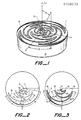
- An antenna in accordance with an embodiment of the invention is shown in Figure 1 with the spherical coordinate system r,8, ⁇ . It consists of four sinuous arms 11 lying on a plane and emanating from a central point 12 located near the Z axis. The arms interleaf each other without touching and are defined such that a rotation of the antenna of 90° about the Z axis leaves the antenna unchanged.
- the arms are excited by a feed network and a four wire transmission line (not shown) connected to the arms at the inner-most points 12 so as to produce currents with equal magnitudes and a progressive phase shift of +90° or -90° to achieve two senses of circular polarization (CP).
- CP circular polarization
- the antenna is placed over a conducting cavitv 13 (usually filled with absorbing material) so as to produce a rotationally symmetric unidirectional pattern with the peak on the Z axis.
- the feed network which may consist of two baluns and a 3db 90° hybrid, may be placed underneath the cavity.
- the four wire transmission line runs from the bottom of the cavity along the Z axis to the feed points 12. Without the cavity, the antenna produces a rotationally symmetric bi-directional pattern with opposite senses of CP in opposite directions.
- the arms consist of metal strips 14 with widths which increase with distance from the center. Printed circuit board techniques may be used to obtain strips with a width and thickness of a few thousandths of an inch.
- the sides of the sinuous arms are defined by curves related to the curve 16 shown in Figure 2.
- the curve consists of P cells numbered 1 to P.
- the line ABC forms cell number 1
- the line CDE forms cell number 2, and so on.
- the radii R p define the outer radius of each cell.
- the design parameters ⁇ p , a positive number, and T a positive number less than 1, define the angular width and ratio of inside to outside radius for each cell, respectively.
- the equation for the curve of the p th cell is given by where r and ⁇ are the polar coordinates of the curve.
- the radii R are related bv
- This type of cell is termed a sine-log cell. If a and ⁇ p are independent of p, then the curve is a log-periodic function of the logarithm of the radius r. If ⁇ p and ⁇ p are not independent of p then we may refer to the curve as a quasi-log periodic curve or a tapered alpha and tau curve.
- the curve is a periodic function of the radius.
- Figure 3 shows a single sinuous arm of the antenna of Figure 1, defined by two curves 17,18 for the p th cell of the form
- the two curves have the same shape as the curve of equation (3) but are rotated plus or minus 6 degrees about the origin.
- the tip or outermost point of a cell occurs at the angle ⁇ p + 6 with respect to the centerline of the arm.
- the arm resembles a wide angle log-periodic zigzag antenna which has been distorted and curved to fit into a circular region.
- the width of a sinuous arm within a cell varies with distance along the arm and the extra metal in the form of a protrusion 19 at the sharp bends forms shunt capacitive loading at these points.
- the four arms of the sinuous antenna behave as transmission lines weaving back and forth in a sinuous manner and supporting essentially an outward traveling wave when excited from the center.
- Radiation from a sinuous arm is small except in radial regions where the electrical path length of a cell is approximately an odd multiple of X/2 where ⁇ is the wavelength.
- the circumferential currents at the beginning and ending of a cell are in phase since they are traveling in opposite directions but one current is delayed 180° in phase with respect to the other.
- These regions are termed active reions and for the full antenna the active reions of the four arms form annular regions or rings with a radial width of a fraction of a wavelength.
- the first active region occurs approximately when where the angles are expressed in radians. It is important that the attenuation of the traveling wave through this first active region be large so that radiation from higher order active regions is negligible.
- Radiation from the spiral antennas in the sum mode occurs in the X ring which has a circumference of X wherein traveling wave currents of the form exp (i ⁇ ) exist and produce circular polarization.
- the basic idea here for the four arm sinuous antenna is to establish the equivalent of standing wave currents of the form sin ⁇ and cos ⁇ for orthogonal pairs of arms and excite the balanced pairs of arms with equal current magnitudes but with +90° or -90° phasing to achieve the equivalence of traveling waves of the form exp ( ⁇ j ⁇ ).
- the radiation from each cell of the single sinuous arm of Figure 3 may be represented as the sum of the radiation from traveling wave currents flowing in opposite directions in the two halves of the cell.
- the sum of the two currents is a standing wave which is approximately a sinusoidal function.
- the bandwidth is controlled by the radii R 1 and R P and values of a and 6 for the first and last cells.
- the high frequency cutoff occurs when where ⁇ H is the wavelength at the high frequency cutoff. In order to obtain good pattern and impendance behaviors it is necessary to have a "transition region" 21 between the feedpoints and the active region at the high frequency cutoff. A reasonable compromise is to use
- the bandwidth may be increased at will by increasing R 1 and/or decreasing Rp. Ten to one bandwidths in the microwave range have been obtained.
- the beamwidth, BW, of the radiation pattern for the active region is inversely proportional to the radius of the active region, i.e.,
- the average 3 db beamwidths are approximately 60, 70, 80 degrees respectively.
- the beamwidth is essentially independent of frequency for frequencies greater than that for which the total active region is within the radius R 1 .
- the control of beamwidth is a luxury provided by the sinuous antennas that is not available with spiral antennas.
- ⁇ p For a given bandwidth the ⁇ p parameters determine the number of cells in the structure. For simplicity of construction, it is desired that ⁇ p be small. For large attenuation through the first active reion and therefore frequency independent performance, ⁇ p must be larger than some minimum value which may be determined experimentally. Measurements indicate that ⁇ p should be greater than .65 in order to obtain rotationally symmetric patterns with low axial ratios over a wide angle of view (like over a hemisphere).
- sinuous antennas may consist of N arms lying on the surface of a plane, cone or pyramid with a rotational symmetry such that a rotation of 360/N degrees about the cental axis leaves the structure unchanged.
- the antenna may be excited in one or more of the normal modes, or eigenvectors, to produce a variety of useful patterns.
- a m is the amplitude of the excitation of mode m and may be a complex number.
- M m is introduced for convenience in describing combinations of modes. It represents the excitation of all N arms in mode m. Mode M N is usually not used since it requires in phase excitation of the arms against an additional conductor. An arbitrary excitation of the antenna may be represented as a summation of the normal modes given by (14). It is obvious that mode M is identical to mode M N-m . All modal patterns have a rotationally symmetric pattern and all modal patterns have a null on the axis of rotation except for modes M I and M -1 . Feed networks may be designed (see later paragraphs) to provide isolated feeds for the individual modes or combinations of the modes. N must be greater than two in order to provide two patterns with orthogonal polarizations.
- Modes M 1 and M -1 are used to provide sum patterns with orthogonal senses of circular polarization.
- Mode combinations M 1 + M -1 and M 1 - M -1 are used to provide sum patterns with orthogonal senses of linear polarization. It should be apparent that the modal amplitudes A 1 and A -1 are 1 and ⁇ 1 for these combinations.
- N must be greater than four in order to provide two rotationally symmetric difference patterns with orthogonal senses of polarization.
- Modes M 2 and M -2 are used to provide difference patterns with opposite senses of circular polarization.
- Modes M 1 and M 2 are used to provide monopulse type direction finding for one sense of circular polarization and modes M -1 and M -2 are used for the other sense of circular polarization.
- Mode combinations M 2 +M -2 and M 2 -M_ 2 may be used to provide difference patterns with orthogonal senses of linear polarization.
- the linear polarization patterns are not very useful for direction finding and homing applications because of polarization errors.
- an antenna with four orthogonal tilted beams For direction finding and homing systems it is often desirable to have an antenna with four orthogonal tilted beams. This may be achieved by combinations of sum and difference modes. For one sense of circular polarization, mode combinations M 1 +M 2 , M 1 -M 2 , M 1 + j M 2 and M 1 -jM 2 are used to provide four orthogonal tilted beams. The other sense of circular polarization is obtained by changing the signs of the above mode numbers. A three db loss in the feed network is incurred since eight beams are obtained from only four normal modes.
- Figure 5 is a perspective view of a six arm 11 log-periodic sinuous antenna placed on a cone 22 with a half angle of a which equals 180- ⁇ 0 .
- the curves defining the arms are similar to those of Figure 2 except that now Figure 2 is considered as a top view of the conical structure and r is considered as the distance from the vertex to a point on the cone.
- the projection of r on the cone to the xy plane is simply r sin 6 0 .
- the design parameters a and T varv from 45 to 60° and .7 to .9 respectively.
- This antenna can be excited in modes M 1 , M -1 , M 2 and M -2 to produce rotationally symmetric sum and difference pattern for both senses of circular polarization.
- the conical structure provides unidirectional patterns in the direction of the zenith.
- the front to back ratio increases as a decreases and is greater than 10 db for a less than about 30°.
- An absorbing cavity 23 may be placed at the base of the cone to reduce pattern perturbation due to reflections from the feed network and supporting structure.
- the advantage of the conical structure is that the gain is several db greater than the gain for a planar structure. For the absorber loaded cavity backed planar structure, at least half of the power is absorbed in the cavity and resistive terminations on the arms.
- the conical structure may be modified to fit an ogive shape commonly used for missiles and high speed aircraft.
- the active region for the conical structure occurs when in a manner similar to that for the planar structures.
- the curve of equation (3) is a sinusoidal function of the logarithm of the radius.
- the curve for each cell could also be defined as a sinusoidal function of the radius or some other oscillating function of the radius.
- An important criteria for an optimum curve is one that maximizes the construction dimensional tolerances.
- the arm widths and spacing between arms may be a few thousandths of an inch.
- An optimum curve may be defined as one which makes the arm widths and spacing commensurate. Curves which come closer to meeting this criteria are described below.
- Figure 6 shows a curve consisting of cells for which each cell is composed of two curves 26,27 and a straight line 28 such as curves AB and CD and the straight line BC for cell number 1.
- the two curves and straight line are linear functions of the logarithm of the radius.
- K is a parameter defining the width of the flat top.
- the curve AB of Figure 6 The equation for the straight line segment or flat top is given by
- Equations (19) and (20) correspond to line segments BC and CD respectively for the first cell.
- a and T p may be a function of p to provide tapered alpha and tau structures.
- a single arm of a linear-log sinuous antenna may be defined by two curves of the form of Figure 6, but rotated +6 and -6 degrees similar to the method used to define the sine-log sinuous arm of Figure 3.
- Figure 7a is a top view of a four arm 11 self-complementary linear-log sinuous antenna.
- the design parameter a varies from 50° to 70° from the inside to outside respectively.
- the parameter ⁇ p varies from .6 to .8 over the same region.
- This top view can be considered that view for either a planar or conical structure.
- the design parameters a and T vary from 55 to 70° and .7 to .9 respectively.
- the arms of the sin-log and linear-log sinuous antennas resemble the conventional log-periodic zigzag antennas which have straight strips or wires connecting alternating sharp bends and are planar or bi-planar wherein the planar structure is bent along the centerline of the zigzag.
- the strips connecting the sharp bends for the sinuous arms are curved in an especial manner such that the arms can interleaf on a common surface without touching or crossing each other and such that one arm is approximately equally spaced from an adjacent arm in the interleaf region. It should be apparent from the previous figures that this is not possible with conventional straight line zigzags except for small interleaf regions.
- the radiation patterns will not be rotationally symmetric and the antenna diameter is much larger than that for a spiral antenna and of course much larger than that for sinuous arms, with large interleaf regions.
- the strips connecting the sharp bends are curved in two dimensions, one to fit the cone and the other to accomplish the large interleaf region as described above.
- the quasi-log periodic sinuous arms can be made self-complementary which is not possible with straight line zigzags, even if they are formed to fit the surface of a cone.
- the arms 11 of the above structures are formed by strips 28 laying on a surface of a plane or a cone.
- Figure 8 shows a single arm of a wire linear-log sinuous antenna in which the arm 29 is defined by the curve of Figure 6 plus the curved protrusions or stubs 31 defined by the angles ⁇ p .
- 6 here defines the length of the stub whereas it was used previously to detine the rotation of curves tor the strip structures. Since the radius ot tne active region is related to a + 6 for both the strip and wire structures, a new parameter was not defined for the stub length.
- the stubs 31 are attached at a radius given by ⁇ p R for the p th cell.
- ⁇ is positive for p even and negative for p odd.
- ⁇ p is defined as a positive number.
- the stubs 31 at the sharp bends produce reflections which tend to cancel the reflections due to the bends.
- the arms may be constructed of conducting wires, rods, tubes or strips. Ideally, the cross-sectional dimensions of the arms should be proportional to the radius, but practically, constant cross-sectional dimensions may be used to achieve large frequency bandwidths. The advantage of this approach is that it is much simpler to prepare the artwork for printed circuit production of the antennas.
- a disadvantage is that the characteristic impedance of the arms may be too large. This may be overcome to some extent by making he wire diameter or strip width large enough to resemble a self-complementary structure at the input region or by tapering the cross-sectional dimensions of the arms with radius to provide a low impedance structure.
- the design parameters a and ⁇ p may be tapered with radius to control the beamwidth variation.
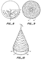
- Figure 9 shows a top view of a four arm linear-log sinuous antenna with T varying from .5 to .82, a varving from 42 to 50° and the stub angle 6 varying from 16 to 20°.
- the first and second numbers of each pair refer to the values at the inside and outside regions of the structure respective.
- Figure 10 is a perspective view of a conical four arm linear-log sinuous antenna having arms 29' and stubs 31' with 8 varying from .5 to .92, a varying from 50 to 70° and 6 varying from 20 to 30°.
- the half cone angle is 20°.
- the curved wire sinuous arms differ from log-periodic wire zigzag antennas not only in the manner described above for sin-log and linear-log sinuous antennas but also in the fact that the stubs are added at the sharp bends.
- the cell is formed by drawing straight lines between these points. Again, ⁇ p , ⁇ p and ⁇ p may be varied with the cell number to control the beamwidth and cutoff frequencies.
- Figure 12 is a top view of a four arm 33 linear wire sinuous antenna with T varying from .5 to .82, a varying from 40 to 60° and 6 varying from 20 to 30°. This can be interpreted as a view of a planar antenna or a pyramidal antenna.
- the dashed lines represent an imaginary square placed around the antenna.
- An application in the HF frequency range would be to use a planar wire structure supported above ground by four poles placed at the corners of the square with the wire antenna supported by dielectric wires running along the diagonals of the square.
- the antenna produces a beam directed to the zenith and provides two orthogonal senses of polarization.
- the elevation pattern will be frequency dependent because of the fixed height above ground.
- This problem may be overcome by using a pyramidal linear wire sinuous antenna such as shown in Figure 13. It has the same design parameters as that for Figure 12 but the structure is projected onto a square pyramid with a half-angle of 45°. If the structure is inverted and placed with the vertex at ground level, then the elevation patterns are essentially frequency independent.
- the dashed lines could represent the outline of a backing cavity.
- the square radiators provide a more compact structure for one and two dimensional arrays of dual polarized antennas.
- the linear wire sinuous arms shown in Figures 11, 12, and 13 differ from conventional log-periodic wire zigzags which have straight wires connecting the sharp turns in several respects.
- the cells are bent toward the vertex in an especial manner such that one arm interleafs adjacent arms as described previously with the constraint that the cells remain on a common surface.
- Two straight lines now connect alternating sharp bends.
- stubs are added at the sharp bends such that they do not touch adjacent arms.
- the zigzag is bent in two dimensions to fit the pyramid and to accomplish the desired interleaf.
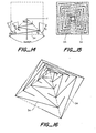
- Figure 14 shows a single arm 34 of a linear sinuous antenna which has only two linear segments per cell if we consider a cell as the line ABC. Since the a angle is fixed at 45°, this antenna does not have the versatility of the previous antenna.
- the polar coordinates of the points are given by
- Figure 15 shows a top view of a planar or pyramidal structure having arms 34 with ⁇ varying from .6 to .9 and 6 varying from 20 to 40°.
- Figure 16 is a perspective view of a linear sinuous antenna with a pyramidal half-angle of 45° with T varying from .5 to .82 and 6 varying from 18 to 30°.
- This structure could be supported by dielectric wires or tubes at the corners of the pyramid.
- This structure is more rugged and simpler to fabricate than that of Figure 13 since the junctions of three conducting wires or tubes occur at the corners rather than the faces of the pyramid.
- the linear wire sinuous arms of Figures 14, 15, and 16 differ from wire zigzag antennas in the sense that stubs are added at the sharp bends.
- the stubs are added in a special manner such that they lie on the common surface and interleaf adjacent arms with approximately equal spacing to adjacent cells of adjacent arms.
- N 5 and 7 are to be avoided since the feed networks are rather complicated.
- the antenna is designed so that it has 60° rotational symmetry.
- the pyramidal structure has a hexagonal cross-section. Bends occur at the corners.
- the angular width of a cell is equal to (a + 6) in which a and/or 6 may be a function of the cell number, p.
- the amount of interleaf between adjacent arms depends upon these angles and the angle 360/N degrees between adjacent arms.
- ILR interleaf ratio
- ILR In order to achieve rotationally symmetric patterns and an antenna diameter comparable to spiral antennas, ILR must be greater than about 0.2. Values less than .2 are considered a small interleaf. Values of ILR considerably greater than one should be avoided since the diameter of the active region becomes too small for sufficient radiation through the active region.
- the design parameter ⁇ must be chosen to make the radial cell length less than about 0.08 in order to make the zigzag element work well. This leads to the condition
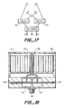
- Figure 17 shows a schematic diagram for the feed network of a four arm sinuous antenna.
- the baluns 36 and 37 are connected to opposite arms 1, 3 and 2, 4 of the antenna to provide the required 180° relative phasing.
- the 3 db quadrature (or 90°) hybrid 38 provides two input ports, A and B, which produce progressive arm phasings of plus or minus 90° as required for the two senses of circular polarization.
- Figures 18, 19 and 20 are sketches showing one embodiment of a planar, cavity backed four arm sinuous antenna with a feed network of the type shown in Figure 17.
- Figure 18 is a cross-sectional view of the central section of the structure.
- the sinuous antenna is etched on the top of a planar printed circuit board 41.
- a cylindrical cavity, 42 is placed below the antenna.
- the inside diameter of the cavity is about X/3 at the low cutoff frequency.
- Absorbing material 43 which is usually in a honey comb form, is placed inside the cavity.
- the baluns and 90° hybrid are enclosed in the metal housing 44.
- Four coaxial lines 46 (only two are shown in this cross section view) run from the antenna surface to the balun cavities 47.
- the inner conductors of the coaxial lines are connected to the arms of the antenna and the outer conductors are bonded together through the height of the cavity.
- the 90° hybrid circuit is etched on both sides of a central dielectric layer 48. Additional printed circuit boards are placed above and below this central layer.
- Two coaxial connectors 49 are placed on the bottom of the structure (only one connector is shown). The same feed structure may be used for a four arm conical sinuous antenna by extending the coaxial lines to the vertex of the cone.
- FIG 19 is a top view of the central dielectric layer 48 showing the strip lines 49 forming the 90° hybrid and the balun feeds.
- the solid and dashed lines show the strips on the top and bottom sides of the layer respectively.
- the hybrid consists of a tandem connection of two 8.3 db hybrids, 51 and 52 to form a 3 db hybrid.
- the hybrids may be of the stepped or continuously tapered form.
- the coupling exists over the lengths 53 and 54 on the right side and similarly for the left side.
- the couplers are bent at he central region which allows a simple modification of existing straight line coupler designs.
- the outlines of the two balun cavities 47 are shown by the dashed lines. Symmetry is invoked to minimize beam tilt and axial ratio. Broadside inputs are placed at 56 and 57.
- the stripline balun feeds are terminated by an open circuit 58, about a quarter wave at midband past the center of the balun.
- FIGS. 20a and 20b Top and side views of one of the baluns are shown in Figures 20a and 20b respectively.
- the balun cavity is excited by the three layer strip line assembly shown in Figure 20b.
- Etched strips 61 Figure 20a
- a gap, 62 are formed on the top and bottom layers and are electrically connected together by pins, 63, at the gap.
- the gap is excited by the strip 64, Figure 20b, on the center layer 66.
- This strip is excited at the top by the hybrid and terminated with an open circuit at the bottom.
- the coaxial lines 66 and 67 run along the sides of the cavity and the strips 61 and are connected in parallel across the gap. This provides a 4:1 impedance transformation between the balanced output coaxial lines and the input strip line.
- One hundred ohm coax lines may be used to provide a 200 ohm balanced feed impedance for the antenna (which is close to the input impedance for a self-complementary structure) and a balun input impedance of 50 ohms.
- the outer conductors of the coaxial lines may be removed inside the cavity and the spacing of the four remaining wires may be tapered to form a wide band transformer.
- the two coaxial lines could also be connected in series. However, this would require 25 ohm coax lines and wideband transformers to match the antenna impedance.
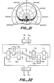
- Figure 21 shows a measured elevation pattern at 5GHZ of a linear-log sinuous wire antenna with four arms.
- the antenna was planar and cavity backed with a cavity diameter of 2.25".
- the pattern was measured with a rotating linearly polarized source.
- the difference between the peak and null envelopes is the axial ratio. It is seen that the axial ratio varies from 0.5 db to 3 db over a hemisphere.
- the 3 db beamwidth is 78°. Measurements over a 9:1 bandwidth showed similar results with a beamwidth variation of about 10° except for the low end of the band.
- the beamwidth variation with azimuth angle is very small which indicates that little energy is propagated past the active region. The variation is much less than that for spiral antennas. This produces much better direction finding accuracy.
- FIG. 22 shows a six arm feed network for producing sum and difference patterns.
- y 35.2° which gives a 2:1 power split.
- the antenna terminals are numbered 1 to 6 and the input terminals are labeled by mode numbers M.
- the phase progression at the antenna terminals is given by m x 60°.
- the feed circuit has 180° rotational symmetry except for the T's at the inputs.
- the boresight error of the difference patterns, M 2 and M_ 2 depends upon the quality of the T's at the inputs.
- Practical considerations for wide bandwidths dictate that each of the components of Figure 22 be composed of a tandem of two couplers, each with a coupling of y/2.
- sixteen couplers are required for the network. For most microwave applications, it is then necessary to stack several layers of components with rather difficult interconnection problems.
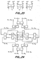
- Figure 24 shows a more sophisticated feed circuit for a six arm sinuous antenna wherein four tilted beams for both senses of circular polarization are provided.
- This circuit has more symmetry and provides much smaller direction finding errors than that of the previous circuit.
- the components labeled IPD are isolated power dividers, usually of the Wilkenson type. A 3db loss in all of the beams is incurred in order to obtain eight beams. It is analogous to the feed circuits for four arm spirals described by J.A. Mosko (Microwave Journal, Vol. 27, No. 3, pp 105-122).
- the ports designated M 1 + M 2 and M 1 - M 2 produce two beams tilted in opposite directions.
- the patterns are simply the sum or difference of the sum and difference patterns.
- the ports designated M 1 - jM 2 and M 1 - jM 2 produce two beams tilted in opposite directions in a plane which is orthogonal to the plane of the previous beams. Similar descriptions apply to the four beams of the opposite polarization designated at the top of the figure.
- the antennas have N sinuous arms placed on a peaked (pyramidal or conical) or planar surface with a symmetry such that a rotation of 360/N . degrees about the central axis leaves the structure unchanged. Three or more arms are required to produce sum type patterns and five or more arms are required to produce sum and difference patterns or titled beams simultaneously.
Landscapes
- Aerials With Secondary Devices (AREA)
- Variable-Direction Aerials And Aerial Arrays (AREA)
- Waveguide Aerials (AREA)
Applications Claiming Priority (2)
| Application Number | Priority Date | Filing Date | Title |
|---|---|---|---|
| US703042 | 1985-02-19 | ||
| US06/703,042 US4658262A (en) | 1985-02-19 | 1985-02-19 | Dual polarized sinuous antennas |
Publications (2)
| Publication Number | Publication Date |
|---|---|
| EP0198578A1 true EP0198578A1 (fr) | 1986-10-22 |
| EP0198578B1 EP0198578B1 (fr) | 1990-09-05 |
Family
ID=24823726
Family Applications (1)
| Application Number | Title | Priority Date | Filing Date |
|---|---|---|---|
| EP86301175A Expired EP0198578B1 (fr) | 1985-02-19 | 1986-02-19 | Antenne sinueuse à double polarisation |
Country Status (6)
| Country | Link |
|---|---|
| US (1) | US4658262A (fr) |
| EP (1) | EP0198578B1 (fr) |
| JP (1) | JPS61256802A (fr) |
| CA (1) | CA1252193A (fr) |
| DE (1) | DE3673851D1 (fr) |
| IL (1) | IL77910A (fr) |
Cited By (22)
| Publication number | Priority date | Publication date | Assignee | Title |
|---|---|---|---|---|
| EP0393875A1 (fr) * | 1989-04-18 | 1990-10-24 | Texas Instruments Incorporated | Antenne compacte à large bande à polarisation multiple |
| EP0416300A3 (en) * | 1989-09-08 | 1991-09-25 | Ball Corporation | Dual polarized spiral antenna |
| EP0482756A3 (en) * | 1990-10-24 | 1992-12-16 | Trw Inc. | Wideband dual polarized multi-mode antenna |
| US5237336A (en) * | 1990-04-27 | 1993-08-17 | Societe Technique D'application Et De Recherche Electronique | Omnidirectional antenna system for radio direction finding |
| US5686929A (en) * | 1994-10-25 | 1997-11-11 | Siemens Aktiengesellschaft | RF homing head antenna system for missiles |
| FR2756976A1 (fr) * | 1996-12-06 | 1998-06-12 | Univ Rennes | Antenne a fentes a double polarisation et a tres large bande passante et procede pour sa realisation |
| GB2330951A (en) * | 1997-11-04 | 1999-05-05 | Nokia Mobile Phones Ltd | Tubular antenna with a tapering conductive serpentine element |
| GB2345798A (en) * | 1999-01-15 | 2000-07-19 | Marconi Electronic Syst Ltd | Broadband antennas |
| US6181297B1 (en) | 1994-08-25 | 2001-01-30 | Symmetricom, Inc. | Antenna |
| US6300917B1 (en) | 1999-05-27 | 2001-10-09 | Sarantel Limited | Antenna |
| US6369776B1 (en) | 1999-02-08 | 2002-04-09 | Sarantel Limited | Antenna |
| RU2191451C2 (ru) * | 2000-12-19 | 2002-10-20 | 16 Центральный научно-исследовательский испытательный институт Министерства обороны Российской Федерации | Кольцевая антенна |
| US6552693B1 (en) | 1998-12-29 | 2003-04-22 | Sarantel Limited | Antenna |
| US6690336B1 (en) | 1998-06-16 | 2004-02-10 | Symmetricom, Inc. | Antenna |
| RU2346364C1 (ru) * | 2007-07-27 | 2009-02-10 | ФГУ 16 Центральный научно-исследовательский испытательный институт Министерства обороны Российской Федерации | Кольцевая антенна |
| FR2925771A1 (fr) * | 2007-12-21 | 2009-06-26 | Thales Sa | Reseau d'antennes directives multi polarisations large bande |
| EP2629367A1 (fr) * | 2012-02-17 | 2013-08-21 | Elettronica S.p.A. | Réseau d'antenne à fente sinueuse surbaissé à bande ultra large |
| EP2642593A1 (fr) * | 2012-03-23 | 2013-09-25 | Broadcom Corporation | Antenne en spirale tridimensionnelle et ses applications |
| CN108199127A (zh) * | 2017-12-30 | 2018-06-22 | 中国船舶重工集团公司第七二三研究所 | 一种双圆极化正弦天线 |
| KR101927708B1 (ko) * | 2018-01-08 | 2019-02-26 | 경남정보대학교 산학협력단 | 마이크로스트립 바룬으로 급전하는 4-암 시누어스 안테나 |
| CN109524771A (zh) * | 2018-11-28 | 2019-03-26 | 哈尔滨工业大学(威海) | 一种基于gcpw馈电的双极化正弦天线装置 |
| CN113834412A (zh) * | 2020-06-08 | 2021-12-24 | 长春市春求科技开发有限公司 | 一种对称度检具及检测键槽对称度的方法 |
Families Citing this family (82)
| Publication number | Priority date | Publication date | Assignee | Title |
|---|---|---|---|---|
| GB8703065D0 (en) * | 1987-02-11 | 1987-05-28 | Marconi Co Ltd | Microwave transformer |
| US6211839B1 (en) * | 1988-08-22 | 2001-04-03 | Trw Inc. | Polarized planar log periodic antenna |
| US5212494A (en) * | 1989-04-18 | 1993-05-18 | Texas Instruments Incorporated | Compact multi-polarized broadband antenna |
| US5227807A (en) * | 1989-11-29 | 1993-07-13 | Ael Defense Corp. | Dual polarized ambidextrous multiple deformed aperture spiral antennas |
| JP2586675B2 (ja) * | 1990-02-27 | 1997-03-05 | 国際電信電話株式会社 | 4線巻ヘリカルアンテナ |
| WO1992013372A1 (fr) * | 1991-01-24 | 1992-08-06 | Rdi Electronics, Inc. | Antenne a large bande |
| US5313216A (en) * | 1991-05-03 | 1994-05-17 | Georgia Tech Research Corporation | Multioctave microstrip antenna |
| US5346300A (en) * | 1991-07-05 | 1994-09-13 | Sharp Kabushiki Kaisha | Back fire helical antenna |
| US5170175A (en) * | 1991-08-23 | 1992-12-08 | Motorola, Inc. | Thin film resistive loading for antennas |
| USH1443H (en) * | 1992-01-17 | 1995-06-06 | The United States Of America As Represented By The Secretary Of The Army | Optically activated multi-frequency high power RF generation utilizing a wafer-scale Si-GaAs substrate |
| USH1460H (en) * | 1992-04-02 | 1995-07-04 | The United States Of America As Represented By The Secretary Of The Air Force | Spiral-mode or sinuous microscrip antenna with variable ground plane spacing |
| US5990847A (en) * | 1996-04-30 | 1999-11-23 | Qualcomm Incorporated | Coupled multi-segment helical antenna |
| US5986620A (en) * | 1996-07-31 | 1999-11-16 | Qualcomm Incorporated | Dual-band coupled segment helical antenna |
| US6184844B1 (en) * | 1997-03-27 | 2001-02-06 | Qualcomm Incorporated | Dual-band helical antenna |
| US5952982A (en) * | 1997-10-01 | 1999-09-14 | Harris Corporation | Broadband circularly polarized antenna |
| US6285323B1 (en) | 1997-10-14 | 2001-09-04 | Mti Technology & Engineering (1993) Ltd. | Flat plate antenna arrays |
| IL121978A (en) * | 1997-10-14 | 2004-05-12 | Mti Wireless Edge Ltd | Flat plate antenna arrays |
| US6072439A (en) * | 1998-01-15 | 2000-06-06 | Andrew Corporation | Base station antenna for dual polarization |
| US5929825A (en) * | 1998-03-09 | 1999-07-27 | Motorola, Inc. | Folded spiral antenna for a portable radio transceiver and method of forming same |
| US5986609A (en) * | 1998-06-03 | 1999-11-16 | Ericsson Inc. | Multiple frequency band antenna |
| US6034649A (en) * | 1998-10-14 | 2000-03-07 | Andrew Corporation | Dual polarized based station antenna |
| US6219006B1 (en) | 1999-02-17 | 2001-04-17 | Ail Systems, Inc. | High efficiency broadband antenna |
| US6130652A (en) * | 1999-06-15 | 2000-10-10 | Trw Inc. | Wideband, dual RHCP, LHCP single aperture direction finding antenna system |
| US6445354B1 (en) | 1999-08-16 | 2002-09-03 | Novatel, Inc. | Aperture coupled slot array antenna |
| US6266027B1 (en) | 1999-11-02 | 2001-07-24 | The United States Of America As Represented By The Secretary Of The Navy | Asymmetric antenna incorporating loads so as to extend bandwidth without increasing antenna size |
| US6317099B1 (en) | 2000-01-10 | 2001-11-13 | Andrew Corporation | Folded dipole antenna |
| US6285336B1 (en) | 1999-11-03 | 2001-09-04 | Andrew Corporation | Folded dipole antenna |
| ES1046677Y (es) * | 2000-06-27 | 2001-11-16 | Martinez Martin Gabriel | Dispositivo regenerador energetico aplicable sobre soportes de audio y video, asi como en aparatos reproductores. |
| US6362796B1 (en) | 2000-09-15 | 2002-03-26 | Bae Systems Aerospace Electronics Inc. | Broadband antenna |
| EP1428292A4 (fr) * | 2001-09-07 | 2004-09-01 | Andrew Corp | Antenne de station de base a large bande et reseau d'antennes |
| JP3923329B2 (ja) * | 2002-02-07 | 2007-05-30 | 株式会社ヨコオ | 複合アンテナ |
| US6621463B1 (en) | 2002-07-11 | 2003-09-16 | Lockheed Martin Corporation | Integrated feed broadband dual polarized antenna |
| US6738026B1 (en) * | 2002-12-09 | 2004-05-18 | Centurion Wireless Technologies, Inc. | Low profile tri-filar, single feed, helical antenna |
| US6853351B1 (en) * | 2002-12-19 | 2005-02-08 | Itt Manufacturing Enterprises, Inc. | Compact high-power reflective-cavity backed spiral antenna |
| WO2004088055A1 (fr) * | 2003-04-04 | 2004-10-14 | Schwarzer Guenther | Dispositif pour recevoir et diffuser des formes d'energie libres |
| US6922179B2 (en) * | 2003-11-17 | 2005-07-26 | Winegard Company | Low profile television antenna |
| JP4197684B2 (ja) * | 2005-03-23 | 2008-12-17 | 株式会社東芝 | 携帯無線機 |
| FR2886413B1 (fr) * | 2005-05-27 | 2007-10-12 | Thales Sa | Procede et dispositif de detection de canalisations enterrees |
| US7292196B2 (en) * | 2005-08-29 | 2007-11-06 | Pharad, Llc | System and apparatus for a wideband omni-directional antenna |
| GB2437998B (en) * | 2006-05-12 | 2009-11-11 | Sarantel Ltd | An antenna system |
| US7808441B2 (en) * | 2007-08-30 | 2010-10-05 | Harris Corporation | Polyhedral antenna and associated methods |
| US7889151B1 (en) * | 2007-11-08 | 2011-02-15 | The United States Of America As Represented By The Secretary Of The Navy | Passive wide-band low-elevation nulling antenna |
| US9496620B2 (en) | 2013-02-04 | 2016-11-15 | Ubiquiti Networks, Inc. | Radio system for long-range high-speed wireless communication |
| US8836601B2 (en) | 2013-02-04 | 2014-09-16 | Ubiquiti Networks, Inc. | Dual receiver/transmitter radio devices with choke |
| US8184061B2 (en) * | 2009-09-16 | 2012-05-22 | Ubiquiti Networks | Antenna system and method |
| US20150244077A1 (en) | 2014-02-25 | 2015-08-27 | Ubiquiti Networks Inc. | Antenna system and method |
| US9147933B2 (en) | 2010-04-11 | 2015-09-29 | Broadcom Corporation | Three-dimensional spiral antenna and applications thereof |
| FR2958804B1 (fr) | 2010-04-13 | 2012-04-27 | Thales Sa | Antenne a polarisation rectiligne, directive, large bande, a grande purete de polarisation. |
| GB201012923D0 (en) | 2010-07-30 | 2010-09-15 | Sarantel Ltd | An antenna |
| US9054416B2 (en) * | 2010-09-20 | 2015-06-09 | Associated Universities, Inc. | Inverted conical sinuous antenna above a ground plane |
| CN102593585B (zh) * | 2012-03-09 | 2015-04-08 | 哈尔滨工业大学(威海) | 一种集成式巴伦馈电的正弦天线装置 |
| CN102790291B (zh) * | 2012-08-18 | 2016-06-01 | 哈尔滨工业大学(威海) | 背腔式宽带双极化天线 |
| EP2920843A4 (fr) | 2012-11-15 | 2016-07-06 | 3M Innovative Properties Co | Antenne spirale pour systèmes de communications sans fil répartis |
| US9543635B2 (en) | 2013-02-04 | 2017-01-10 | Ubiquiti Networks, Inc. | Operation of radio devices for long-range high-speed wireless communication |
| US9397820B2 (en) | 2013-02-04 | 2016-07-19 | Ubiquiti Networks, Inc. | Agile duplexing wireless radio devices |
| US8855730B2 (en) | 2013-02-08 | 2014-10-07 | Ubiquiti Networks, Inc. | Transmission and reception of high-speed wireless communication using a stacked array antenna |
| DE102013004774B3 (de) * | 2013-03-20 | 2014-09-25 | Cetecom Gmbh | Zirkular polarisierte Breitbandantenne und Anordnung derselben in einem reflektionsarmen Raum |
| EP3055930B1 (fr) | 2013-10-11 | 2019-11-20 | Ubiquiti Inc. | Optimisation de système radio sans fil par analyse continue du spectre |
| WO2015069309A1 (fr) * | 2013-11-07 | 2015-05-14 | Laird Technologies, Inc. | Antennes à large bande omnidirectionnelles |
| USD711859S1 (en) * | 2013-12-27 | 2014-08-26 | Megabyte Limited | Antenna for radio frequency tag reader |
| US20150256355A1 (en) | 2014-03-07 | 2015-09-10 | Robert J. Pera | Wall-mounted interactive sensing and audio-visual node devices for networked living and work spaces |
| US9172605B2 (en) | 2014-03-07 | 2015-10-27 | Ubiquiti Networks, Inc. | Cloud device identification and authentication |
| US9912053B2 (en) | 2014-03-17 | 2018-03-06 | Ubiquiti Networks, Inc. | Array antennas having a plurality of directional beams |
| CN104981941B (zh) | 2014-04-01 | 2018-02-02 | 优倍快网络公司 | 天线组件 |
| US9906202B1 (en) * | 2014-04-23 | 2018-02-27 | Lockheed Martin Corporation | Multi-layer wideband antenna with integrated impedance matching |
| US9779868B2 (en) * | 2014-04-30 | 2017-10-03 | Qorvo Us, Inc. | Compact impedance transformer |
| US10177451B1 (en) * | 2014-08-26 | 2019-01-08 | Ball Aerospace & Technologies Corp. | Wideband adaptive beamforming methods and systems |
| EP3041135A1 (fr) | 2014-12-30 | 2016-07-06 | Elettronica S.p.A. | Balun actif et circuit intégré monolithique à micro-ondes l'intégrant pour la réception à bande ultralarge |
| EP3266066B1 (fr) * | 2015-03-03 | 2022-06-15 | The Government of the United States of America as represented by the Secretary of the Navy | Élément d'antenne à bande ultra-large à bande passante décadique à faible polarisation croisée |
| RU167585U1 (ru) * | 2015-12-28 | 2017-01-10 | федеральное государственное бюджетное образовательное учреждение высшего образования "Нижегородский государственный технический университет им. Р.Е. Алексеева" (НГТУ) | Многочастотная планарная щелевая антенна типа ракушка на две поляризации |
| US10923825B2 (en) | 2017-07-12 | 2021-02-16 | Src, Inc. | Spiral antenna system |
| US11495886B2 (en) * | 2018-01-04 | 2022-11-08 | The Board Of Trustees Of The University Of Alabama | Cavity-backed spiral antenna with perturbation elements |
| KR102048996B1 (ko) * | 2018-12-18 | 2019-11-27 | 국방과학연구소 | 교차편파 격리도 개선 위한 이중선형 편파 시뉴어스 안테나 |
| CN109786981A (zh) * | 2019-03-05 | 2019-05-21 | 深圳市摩尔环宇通信技术有限公司 | 一种5g毫米波耦合板及其设计方法和装置以及设备 |
| CN110085982B (zh) * | 2019-05-15 | 2024-03-15 | 中山香山微波科技有限公司 | 超宽带双极化天线及其制作方法 |
| RU193058U1 (ru) * | 2019-06-28 | 2019-10-11 | федеральное государственное бюджетное образовательное учреждение высшего образования "Нижегородский государственный технический университет им. Р.Е. Алексеева" (НГТУ) | Узкополосная двухщелевая ячейка с копланарными линиями и болометрами на холодных электронах для многочастотного массива антенн |
| US11303034B2 (en) | 2019-12-16 | 2022-04-12 | City University Of Hong Kong | Parallel-plate antenna |
| KR102414217B1 (ko) | 2021-03-16 | 2022-06-27 | 연세대학교 산학협력단 | 낮은 입력 임피던스를 위한 4 개의 팔을 갖는 시뉴어스 안테나 |
| KR102414218B1 (ko) | 2021-03-16 | 2022-06-27 | 연세대학교 산학협력단 | 4 개의 팔을 갖는 시뉴어스 안테나의 초광대역 동작을 위한 급전 구조 |
| US12512591B1 (en) * | 2022-02-01 | 2025-12-30 | Lockheed Martin Corporation | Partially metalized antenna cavity for planar antennas |
| GB2625989B (en) | 2023-01-03 | 2025-09-24 | Leonardo UK Ltd | An antenna |
| GB2701498A (en) | 2024-09-09 | 2026-04-29 | Leonardo UK Ltd | A mirror assembly for a combined radio frequency (rf) and electro-optical system |
Citations (6)
| Publication number | Priority date | Publication date | Assignee | Title |
|---|---|---|---|---|
| US2985879A (en) * | 1958-07-09 | 1961-05-23 | Univ Illinois | Frequency independent antennas |
| GB1148320A (en) * | 1965-05-21 | 1969-04-10 | Telefunken Patent | Improvements in or relating to logarithmic aerial systems |
| US3555554A (en) * | 1969-03-03 | 1971-01-12 | Sylvania Electric Prod | Cavity-backed spiral antenna with mode suppression |
| US3562756A (en) * | 1968-06-03 | 1971-02-09 | Texas Instruments Inc | Multiple polarization spiral antenna |
| US3681772A (en) * | 1970-12-31 | 1972-08-01 | Trw Inc | Modulated arm width spiral antenna |
| US4243993A (en) * | 1979-11-13 | 1981-01-06 | The Boeing Company | Broadband center-fed spiral antenna |
Family Cites Families (1)
| Publication number | Priority date | Publication date | Assignee | Title |
|---|---|---|---|---|
| US4490725A (en) * | 1981-10-09 | 1984-12-25 | Gte Products Corporation | Log-periodic antenna |
-
1985
- 1985-02-19 US US06/703,042 patent/US4658262A/en not_active Expired - Lifetime
-
1986
- 1986-02-10 CA CA000501446A patent/CA1252193A/fr not_active Expired
- 1986-02-18 IL IL77910A patent/IL77910A/xx not_active IP Right Cessation
- 1986-02-19 EP EP86301175A patent/EP0198578B1/fr not_active Expired
- 1986-02-19 JP JP61034958A patent/JPS61256802A/ja active Pending
- 1986-02-19 DE DE8686301175T patent/DE3673851D1/de not_active Expired - Lifetime
Patent Citations (6)
| Publication number | Priority date | Publication date | Assignee | Title |
|---|---|---|---|---|
| US2985879A (en) * | 1958-07-09 | 1961-05-23 | Univ Illinois | Frequency independent antennas |
| GB1148320A (en) * | 1965-05-21 | 1969-04-10 | Telefunken Patent | Improvements in or relating to logarithmic aerial systems |
| US3562756A (en) * | 1968-06-03 | 1971-02-09 | Texas Instruments Inc | Multiple polarization spiral antenna |
| US3555554A (en) * | 1969-03-03 | 1971-01-12 | Sylvania Electric Prod | Cavity-backed spiral antenna with mode suppression |
| US3681772A (en) * | 1970-12-31 | 1972-08-01 | Trw Inc | Modulated arm width spiral antenna |
| US4243993A (en) * | 1979-11-13 | 1981-01-06 | The Boeing Company | Broadband center-fed spiral antenna |
Non-Patent Citations (2)
| Title |
|---|
| MICROWAVE JOURNAL, vol. 27, no, 3, March 1984, pages 105-122; J.A. MOSKO "An introduction to wideband, two-channel, direction-finding systems: Part II" * |
| NACHRICHTENTECHNISCHE FACHBERICHTE NTF, vol. 23, 1961, pages 81-93; R. GREIF "Logarithmisch periodische Antennen" * |
Cited By (27)
| Publication number | Priority date | Publication date | Assignee | Title |
|---|---|---|---|---|
| EP0393875A1 (fr) * | 1989-04-18 | 1990-10-24 | Texas Instruments Incorporated | Antenne compacte à large bande à polarisation multiple |
| EP0416300A3 (en) * | 1989-09-08 | 1991-09-25 | Ball Corporation | Dual polarized spiral antenna |
| US5237336A (en) * | 1990-04-27 | 1993-08-17 | Societe Technique D'application Et De Recherche Electronique | Omnidirectional antenna system for radio direction finding |
| EP0482756A3 (en) * | 1990-10-24 | 1992-12-16 | Trw Inc. | Wideband dual polarized multi-mode antenna |
| US6181297B1 (en) | 1994-08-25 | 2001-01-30 | Symmetricom, Inc. | Antenna |
| US5686929A (en) * | 1994-10-25 | 1997-11-11 | Siemens Aktiengesellschaft | RF homing head antenna system for missiles |
| FR2756976A1 (fr) * | 1996-12-06 | 1998-06-12 | Univ Rennes | Antenne a fentes a double polarisation et a tres large bande passante et procede pour sa realisation |
| GB2330951A (en) * | 1997-11-04 | 1999-05-05 | Nokia Mobile Phones Ltd | Tubular antenna with a tapering conductive serpentine element |
| US6094179A (en) * | 1997-11-04 | 2000-07-25 | Nokia Mobile Phones Limited | Antenna |
| GB2330951B (en) * | 1997-11-04 | 2002-09-18 | Nokia Mobile Phones Ltd | Antenna |
| US6690336B1 (en) | 1998-06-16 | 2004-02-10 | Symmetricom, Inc. | Antenna |
| US6552693B1 (en) | 1998-12-29 | 2003-04-22 | Sarantel Limited | Antenna |
| GB2345798A (en) * | 1999-01-15 | 2000-07-19 | Marconi Electronic Syst Ltd | Broadband antennas |
| EP1026777A3 (fr) * | 1999-01-15 | 2000-08-16 | Marconi Electronic Systems Limited | Antenne en forme spirale et sinueuse à large bande |
| US6191756B1 (en) | 1999-01-15 | 2001-02-20 | Marconi Electronic Systems Limited | Broad band antennas |
| US6369776B1 (en) | 1999-02-08 | 2002-04-09 | Sarantel Limited | Antenna |
| US6300917B1 (en) | 1999-05-27 | 2001-10-09 | Sarantel Limited | Antenna |
| RU2191451C2 (ru) * | 2000-12-19 | 2002-10-20 | 16 Центральный научно-исследовательский испытательный институт Министерства обороны Российской Федерации | Кольцевая антенна |
| RU2346364C1 (ru) * | 2007-07-27 | 2009-02-10 | ФГУ 16 Центральный научно-исследовательский испытательный институт Министерства обороны Российской Федерации | Кольцевая антенна |
| FR2925771A1 (fr) * | 2007-12-21 | 2009-06-26 | Thales Sa | Reseau d'antennes directives multi polarisations large bande |
| WO2009083511A1 (fr) | 2007-12-21 | 2009-07-09 | Thales | Reseau d'antennes directives multi polarisations large bande |
| EP2629367A1 (fr) * | 2012-02-17 | 2013-08-21 | Elettronica S.p.A. | Réseau d'antenne à fente sinueuse surbaissé à bande ultra large |
| EP2642593A1 (fr) * | 2012-03-23 | 2013-09-25 | Broadcom Corporation | Antenne en spirale tridimensionnelle et ses applications |
| CN108199127A (zh) * | 2017-12-30 | 2018-06-22 | 中国船舶重工集团公司第七二三研究所 | 一种双圆极化正弦天线 |
| KR101927708B1 (ko) * | 2018-01-08 | 2019-02-26 | 경남정보대학교 산학협력단 | 마이크로스트립 바룬으로 급전하는 4-암 시누어스 안테나 |
| CN109524771A (zh) * | 2018-11-28 | 2019-03-26 | 哈尔滨工业大学(威海) | 一种基于gcpw馈电的双极化正弦天线装置 |
| CN113834412A (zh) * | 2020-06-08 | 2021-12-24 | 长春市春求科技开发有限公司 | 一种对称度检具及检测键槽对称度的方法 |
Also Published As
| Publication number | Publication date |
|---|---|
| IL77910A (en) | 1989-09-10 |
| JPS61256802A (ja) | 1986-11-14 |
| US4658262A (en) | 1987-04-14 |
| DE3673851D1 (de) | 1990-10-11 |
| CA1252193A (fr) | 1989-04-04 |
| EP0198578B1 (fr) | 1990-09-05 |
Similar Documents
| Publication | Publication Date | Title |
|---|---|---|
| EP0198578B1 (fr) | Antenne sinueuse à double polarisation | |
| AU613645B2 (en) | Broadband notch antenna | |
| US4243993A (en) | Broadband center-fed spiral antenna | |
| US4054874A (en) | Microstrip-dipole antenna elements and arrays thereof | |
| US5451973A (en) | Multi-mode dual circularly polarized spiral antenna | |
| JP4675894B2 (ja) | 周波数に依存しない放射特性を有した広帯域マルチダイポールアンテナ | |
| US4125837A (en) | Dual notch fed electric microstrip dipole antennas | |
| EP0377858B1 (fr) | Antenne encastrée à ondes de surface | |
| Bawer et al. | The spiral antenna | |
| US3803623A (en) | Microstrip antenna | |
| US4114164A (en) | Broadband spiral antenna | |
| US2914766A (en) | Three conductor planar antenna | |
| US4630064A (en) | Spiral antenna with selectable impedance | |
| US6023250A (en) | Compact, phasable, multioctave, planar, high efficiency, spiral mode antenna | |
| KR101927708B1 (ko) | 마이크로스트립 바룬으로 급전하는 4-암 시누어스 안테나 | |
| EP0018476A1 (fr) | Antenne du type à cavité résonnante à feutes croisées | |
| US3987455A (en) | Microstrip antenna | |
| WO2000076029A1 (fr) | Element rayonnant d'antenne en quatre carres a bords rognes | |
| US6982676B2 (en) | Plano-convex rotman lenses, an ultra wideband array employing a hybrid long slot aperture and a quasi-optic beam former | |
| CA1125396A (fr) | Dispositif de terminaison pour micro-ondes | |
| US3681772A (en) | Modulated arm width spiral antenna | |
| US4605934A (en) | Broad band spiral antenna with tapered arm width modulation | |
| EP0468413A2 (fr) | Antenne plane avec rendement et gain élévés | |
| US3641579A (en) | FREQUENCY-INDEPENDENT IcR ANTENNA | |
| Jordan et al. | Developments in broadband antennas |
Legal Events
| Date | Code | Title | Description |
|---|---|---|---|
| PUAI | Public reference made under article 153(3) epc to a published international application that has entered the european phase |
Free format text: ORIGINAL CODE: 0009012 |
|
| AK | Designated contracting states |
Kind code of ref document: A1 Designated state(s): DE FR GB IT |
|
| 17P | Request for examination filed |
Effective date: 19870217 |
|
| 17Q | First examination report despatched |
Effective date: 19880701 |
|
| GRAA | (expected) grant |
Free format text: ORIGINAL CODE: 0009210 |
|
| AK | Designated contracting states |
Kind code of ref document: B1 Designated state(s): DE FR GB IT |
|
| REF | Corresponds to: |
Ref document number: 3673851 Country of ref document: DE Date of ref document: 19901011 |
|
| ET | Fr: translation filed | ||
| ITF | It: translation for a ep patent filed | ||
| ITTA | It: last paid annual fee | ||
| PLBE | No opposition filed within time limit |
Free format text: ORIGINAL CODE: 0009261 |
|
| STAA | Information on the status of an ep patent application or granted ep patent |
Free format text: STATUS: NO OPPOSITION FILED WITHIN TIME LIMIT |
|
| 26N | No opposition filed | ||
| REG | Reference to a national code |
Ref country code: GB Ref legal event code: IF02 |
|
| PGFP | Annual fee paid to national office [announced via postgrant information from national office to epo] |
Ref country code: GB Payment date: 20040211 Year of fee payment: 19 |
|
| PGFP | Annual fee paid to national office [announced via postgrant information from national office to epo] |
Ref country code: FR Payment date: 20040219 Year of fee payment: 19 |
|
| PGFP | Annual fee paid to national office [announced via postgrant information from national office to epo] |
Ref country code: DE Payment date: 20040331 Year of fee payment: 19 |
|
| PG25 | Lapsed in a contracting state [announced via postgrant information from national office to epo] |
Ref country code: IT Free format text: LAPSE BECAUSE OF NON-PAYMENT OF DUE FEES;WARNING: LAPSES OF ITALIAN PATENTS WITH EFFECTIVE DATE BEFORE 2007 MAY HAVE OCCURRED AT ANY TIME BEFORE 2007. THE CORRECT EFFECTIVE DATE MAY BE DIFFERENT FROM THE ONE RECORDED. Effective date: 20050219 Ref country code: GB Free format text: LAPSE BECAUSE OF NON-PAYMENT OF DUE FEES Effective date: 20050219 |
|
| PG25 | Lapsed in a contracting state [announced via postgrant information from national office to epo] |
Ref country code: DE Free format text: LAPSE BECAUSE OF NON-PAYMENT OF DUE FEES Effective date: 20050901 |
|
| GBPC | Gb: european patent ceased through non-payment of renewal fee |
Effective date: 20050219 |
|
| PG25 | Lapsed in a contracting state [announced via postgrant information from national office to epo] |
Ref country code: FR Free format text: LAPSE BECAUSE OF NON-PAYMENT OF DUE FEES Effective date: 20051031 |
|
| REG | Reference to a national code |
Ref country code: FR Ref legal event code: ST Effective date: 20051031 |