EP0198657B1 - Verbinder für optische Fasern - Google Patents
Verbinder für optische Fasern Download PDFInfo
- Publication number
- EP0198657B1 EP0198657B1 EP86302609A EP86302609A EP0198657B1 EP 0198657 B1 EP0198657 B1 EP 0198657B1 EP 86302609 A EP86302609 A EP 86302609A EP 86302609 A EP86302609 A EP 86302609A EP 0198657 B1 EP0198657 B1 EP 0198657B1
- Authority
- EP
- European Patent Office
- Prior art keywords
- fibre
- lens
- fibres
- ferrule
- securing
- Prior art date
- Legal status (The legal status is an assumption and is not a legal conclusion. Google has not performed a legal analysis and makes no representation as to the accuracy of the status listed.)
- Expired - Lifetime
Links
- 230000003287 optical effect Effects 0.000 title claims description 57
- 239000000835 fiber Substances 0.000 claims description 179
- 230000008878 coupling Effects 0.000 claims description 65
- 238000010168 coupling process Methods 0.000 claims description 65
- 238000005859 coupling reaction Methods 0.000 claims description 65
- 239000013307 optical fiber Substances 0.000 claims description 43
- 239000000463 material Substances 0.000 claims description 33
- 238000005253 cladding Methods 0.000 claims description 20
- 238000000034 method Methods 0.000 claims description 19
- 238000012544 monitoring process Methods 0.000 claims description 18
- 230000005540 biological transmission Effects 0.000 claims description 17
- 230000013011 mating Effects 0.000 claims description 16
- 238000003384 imaging method Methods 0.000 claims description 15
- 238000000576 coating method Methods 0.000 claims description 12
- 230000000694 effects Effects 0.000 claims description 12
- 239000011248 coating agent Substances 0.000 claims description 11
- 125000006850 spacer group Chemical group 0.000 claims description 11
- 238000012360 testing method Methods 0.000 claims description 11
- 239000011800 void material Substances 0.000 claims description 8
- 239000004033 plastic Substances 0.000 claims description 6
- 229920003023 plastic Polymers 0.000 claims description 6
- 238000007789 sealing Methods 0.000 claims description 5
- 239000012530 fluid Substances 0.000 claims description 4
- 229920001971 elastomer Polymers 0.000 claims description 3
- 239000005060 rubber Substances 0.000 claims description 3
- 229910052751 metal Inorganic materials 0.000 claims description 2
- 239000002184 metal Substances 0.000 claims description 2
- 239000012780 transparent material Substances 0.000 claims 3
- 150000002739 metals Chemical class 0.000 claims 1
- 230000000712 assembly Effects 0.000 description 20
- 238000000429 assembly Methods 0.000 description 20
- 229920005989 resin Polymers 0.000 description 12
- 239000011347 resin Substances 0.000 description 12
- 230000007246 mechanism Effects 0.000 description 7
- 239000006223 plastic coating Substances 0.000 description 6
- 238000010276 construction Methods 0.000 description 5
- 238000004519 manufacturing process Methods 0.000 description 5
- VYPSYNLAJGMNEJ-UHFFFAOYSA-N Silicium dioxide Chemical compound O=[Si]=O VYPSYNLAJGMNEJ-UHFFFAOYSA-N 0.000 description 4
- 238000003780 insertion Methods 0.000 description 4
- 230000037431 insertion Effects 0.000 description 4
- 238000004382 potting Methods 0.000 description 4
- 238000000926 separation method Methods 0.000 description 4
- 238000006073 displacement reaction Methods 0.000 description 3
- 238000005516 engineering process Methods 0.000 description 3
- 238000004026 adhesive bonding Methods 0.000 description 2
- 230000008901 benefit Effects 0.000 description 2
- 239000000919 ceramic Substances 0.000 description 2
- 239000002131 composite material Substances 0.000 description 2
- 150000001875 compounds Chemical class 0.000 description 2
- 239000003822 epoxy resin Substances 0.000 description 2
- 239000011521 glass Substances 0.000 description 2
- 239000003292 glue Substances 0.000 description 2
- 229920000647 polyepoxide Polymers 0.000 description 2
- 101100117236 Drosophila melanogaster speck gene Proteins 0.000 description 1
- 230000004075 alteration Effects 0.000 description 1
- 239000000969 carrier Substances 0.000 description 1
- 230000008859 change Effects 0.000 description 1
- 238000002788 crimping Methods 0.000 description 1
- 230000007423 decrease Effects 0.000 description 1
- 230000001419 dependent effect Effects 0.000 description 1
- 239000002305 electric material Substances 0.000 description 1
- 230000002349 favourable effect Effects 0.000 description 1
- 239000005357 flat glass Substances 0.000 description 1
- 229920002457 flexible plastic Polymers 0.000 description 1
- 229910052738 indium Inorganic materials 0.000 description 1
- APFVFJFRJDLVQX-UHFFFAOYSA-N indium atom Chemical compound [In] APFVFJFRJDLVQX-UHFFFAOYSA-N 0.000 description 1
- 238000002347 injection Methods 0.000 description 1
- 239000007924 injection Substances 0.000 description 1
- 210000001503 joint Anatomy 0.000 description 1
- 238000012423 maintenance Methods 0.000 description 1
- 230000004048 modification Effects 0.000 description 1
- 238000012986 modification Methods 0.000 description 1
- 230000007935 neutral effect Effects 0.000 description 1
- 238000005498 polishing Methods 0.000 description 1
- 230000008569 process Effects 0.000 description 1
- 230000001681 protective effect Effects 0.000 description 1
- 230000005855 radiation Effects 0.000 description 1
- 230000009467 reduction Effects 0.000 description 1
- 238000009877 rendering Methods 0.000 description 1
- 239000012858 resilient material Substances 0.000 description 1
- 230000000630 rising effect Effects 0.000 description 1
- 238000010187 selection method Methods 0.000 description 1
- 230000035945 sensitivity Effects 0.000 description 1
- 239000000377 silicon dioxide Substances 0.000 description 1
- 229910000679 solder Inorganic materials 0.000 description 1
- 239000000725 suspension Substances 0.000 description 1
- 238000013519 translation Methods 0.000 description 1
Images


Classifications
-
- G—PHYSICS
- G02—OPTICS
- G02B—OPTICAL ELEMENTS, SYSTEMS OR APPARATUS
- G02B6/00—Light guides; Structural details of arrangements comprising light guides and other optical elements, e.g. couplings
- G02B6/24—Coupling light guides
- G02B6/26—Optical coupling means
- G02B6/32—Optical coupling means having lens focusing means positioned between opposed fibre ends
-
- G—PHYSICS
- G02—OPTICS
- G02B—OPTICAL ELEMENTS, SYSTEMS OR APPARATUS
- G02B6/00—Light guides; Structural details of arrangements comprising light guides and other optical elements, e.g. couplings
- G02B6/24—Coupling light guides
- G02B6/36—Mechanical coupling means
- G02B6/38—Mechanical coupling means having fibre to fibre mating means
- G02B6/3807—Dismountable connectors, i.e. comprising plugs
- G02B6/3833—Details of mounting fibres in ferrules; Assembly methods; Manufacture
- G02B6/3834—Means for centering or aligning the light guide within the ferrule
- G02B6/3843—Means for centering or aligning the light guide within the ferrule with auxiliary facilities for movably aligning or adjusting the fibre within its ferrule, e.g. measuring position or eccentricity
Definitions
- the present invention relates to connectors used to effect connections between separate lengths of optical fibres, and more particularly to connectors which are adjustable to optimize the transmission of light energy through the joint and which do not lose their adjustment when one or the other fibre is disconnected from and reconnected to the connector.
- optical fibres for the transmission of data or optical information has increased dramatically in recent years.
- the heart of such transmission systems is an optical fibre of silica glass or other suitable material which has been clad with an appropriate material to achieve a "light tube” or waveguide along which light energy can travel in a controlled manner.
- Optical fibres are extremely small (maybe 100 microns in diameter) and when they are incorporated into a data transmission system it is necessary to effect inter-connections between separate lengths of such fibres.
- the primary function of an optical connector is to provide a low-loss coupling of light energy from one fibre to the next and it is necessary to align, in an extremely precise manner, the cores of the coupled fibres so as to keep the losses at the joint to an absolute minimum.
- any fibre to fibre coupling system There are six main sources of losses in any fibre to fibre coupling system. The greatest losses are due to lateral misalignment, when the mating fibres are not aligned along their central axes. Also, although manufacturers place tight tolerances on the position of the core within the cladding, any eccentricity of the central core is treated as a lateral misalignment condition. Angular losses occur when the central axes of the two fibres are tilted with respect to each other. End separation losses occur when the ends of the mating fibre are separated. Greater separations result in greater losses since light emananting from the end of an optical fibre is projected in the form of a cone. Dirt, surface irregularities and non-perpendicular ends conspire to keep the ends apart and generate losses.
- Extrinsic connector Intrinsic fibre losses are caused by variations in the optical parameters of the fibre, including its "numerical aperture” (NA), concentricity of the core, core ellipticity and diameter variations.
- NA numerical aperture
- fresnel losses occur whenever light passes from one transparent medium into another medium of a different index of refraction, since part of the transmitted light will be lost to a reflected beam.
- fresnel losses can be 0.2dB for each surface. This loss can be eliminated by using index-matching fluids, or reduced by using anti-reflection coatings.
- the losses should be the same with an expanded beam coupler.
- couplers using expanded beam technology are presently available commercially.
- One of the easiest lens to use in fibre connectors is the graded index (GRIN) lens.
- Cylindrical GRIN lenses are functionally identical to conventional spherical lenses except that they have flat end surfaces.
- the change in the index of refraction along its axis generates the unique properties of the GRIN lens and lenses can be tailored by the manufacturer to generate a wide range of optical parameters.
- the length of a lens defines its pitch, or the fraction of a complete wavelength, that is contained within the lens at a particular wavelength. For the production of a collimated beam from a point source it is necessary to use a quarter-pitch lens.
- U.S. Patent 4,265,511 discloses a multi-piece connector in which two sections, each carrying a ferrule containing an optical fibre, are threadedly connected together to bring opposing reference faces into contact with each other. Each ferrule contacts, and pivots on, a spherical lens. Adjusting means are provided at the opposite ends of the ferrules for adjusting the optical axis of the fibre carried thereby so that it is parallel to the optical axis of the housing.
- U.S. Patent 4,290,667 discloses a plurality of different terminations for an optical fibre, each involving a beam expanding lens. Adjustment is available to ensure that the fibre end coincides with the lens focus, by way of an adjusting screw.
- the present invention is defined in the independent claims and is intended to overcome specifically the tilt problems associated with beam expanding or imaging lens type connectors or couplers and the extremely high tolerance requirements of placing the fibre end at the focal point of the lens.
- the present invention is embodied in a new connector or coupling device which is economical to manufacture, may be easily hermetically sealed in use, is effortlessly manipulated during disconnection and reconnection, and is adjustable to optimize the transmission of light energy therethrough.
- the coupling device of the present invention uses the properties of lenses in combination with novel tilting techniques to achieve a compact structure capable of submicron resolution. Furthermore, with very little, or even no, adjustment devices embodying the principles of the present invention could be used as source couplers, attenuators or connectors to couple light into any size or number of receiving fibre(s).
- the present invention utilizes a pair of base plates each having a threaded boss thereon and an axial bore therethrough. Each bore is adapted to receive in a predetermined position therein a holder which carries a beam expanding or imaging lens and an optical fibre associated therewith.
- the lens holder has a nut thereon for threaded connection to the boss of the base plate such that the holder can be disconnected from the base plate and reconnected thereto.
- a resilient member is sandwiched between confronting faces of the base plate and threaded screws interconnect the base plates by passing from one plate through the resilient member to the other plate.
- the central void area of the resilient member contains the opposing faces of the lenses and may be hermetically sealed from the surrounding atmosphere by sealing contact with the base plates.
- a test light can be transmitted from one fibre through the connection to the other fibre and then to a suitable receiver.
- the threaded screws can then be adjusted to alter the angular orientation of one base plate relative to the other so as to alter the angular orientation of one lens and its fibre relative to the other.
- the receiver is monitored and the screws are adjusted in a pattern until the detected output is optimized at which point the adjusting procedure is stopped. Even if one or both of the fibres is disconnected from the joint as described above the base plates will hold their adjusted condition and the fibres can be reconnected to the joint without fear of any increase in losses after reconnection.
- the present invention may be considered as providing a coupling device for optically coupling a pair of optical fibres in end-to-end relation, each of the fibres terminating at a beam expanding or imaging lens, comprising: base means for each of the fibres, each such base means including an axial bore and means for securing one of the lenses therein; a resilient member positionable between and against confronting end faces of the base means, the resilient member permitting passage of light energy thereacross; and axially extending securing and adjusting means interconnecting the base means with the resilient member trapped therebetween; whereby the securing and adjusting means are individually axially displaceable to effect an angular adjustment of one base means relative to the other so as to optimize the light energy transmissable from one fibre and its lens to the other lens and its fibre.
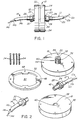
- Figure 1 is a side view of the optical fibre coupling device of the present invention.
- Figure 2 is a composite view of the major components of the coupling device of the present invention.
- Figure 3 is a cross-section of an optical fibre and lens holder receivable in a base plate of the present invention.
- Figure 4 is a side view of a second embodiment coupling device in accordance with the present invention.
- Figure 5 is a composite view of the major components of the second embodiment of the present invention.
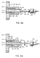
- Figures 6A and 6B show simplified cross-sectional views of the connections possible with the second embodiment.
- Figure 7 shows a tool usable to insert the components of the second embodiment.
- Figure 8 shows a bulkhead connector using the principles of the present invention.
- Figures 9 and 10 show cross-sectional views of two one-end couplers (optical switches) with the coupler of Fig. 10 using the principles of the present invention.
- Figures 11A, 11B, 11C and 12 show monitoring connectors unable with the present invention.
- FIG. 13 shows a beam splitter using the principles of the present invention.
- Figures 14 and 15 show two embodiments of a radially adjustable coupling device using the principles of the present invention.
- Figure 16 shows an embodiment similar to that of Figure 1 but using a hemispherical fulcrum about which tilt adjustment is possible.
- Figure 17 shows an embodiment similar to that of Figure 15 but using a spherical fulcrum member for tilt adjustment.
- Figure 18 shows an embodiment similar to that of Figure 15 but using a spherical lens instead of a cylindrical lens.
- Figure 19 shows another embodiment similar in some respects to that of Figure 16.
- the basic optical fibre coupling device according to the present invention is illustrated in Figure 1 under reference number 10.
- the coupling device 10 is used to join a pair of optical fibre assemblies 12,14 in end-to-end relation so that an optical signal in the form of light energy can be transmitted from one assembly to the other with minimum losses at the joint.
- the optical fibre assemblies 12,14 typically include the clad optical fibre core 12a,14a a plastic coating 12b,14b surrounding the core and a protective cable or sheath 12c,14c surrounding the coating.
- each clad fibre core 12a,14a terminates at a graded index lens (GRIN) 72, which with the fibre core end being positioned at the focal point of the lens, expands and collimates the optical signal for improved transmission to the receiving GRIN lens.
- GRIN graded index lens
- Suitable GRIN lenses for the present invention are available under the SELFOC (Trademark) designation from the Nippon Sheet Glass Company.
- each optical fibre assembly 12,14 is received in a corresponding base plate 16,18 via an appropriate connection mechanism to be described herein.
- Each base plate, 16,18 is provided with a central boss 20,22 projecting outwardly from one face thereof.
- Each boss carries external threads 36 and a central bore 38 extends axially through the boss and its base plate to exit at the flat obverse face thereof.
- a keyway 40 is machined in the sidewall of the bore 38 for a purpose to be described.
- Each fibre assembly 12,14 carries at its end a lens holder 24,28 and each lens holder in turn carries a nut 26,30 which is free to rotate thereon. Furthermore each lens holder carries a key 42, which is matable with the keyway 40 provided in the axial bore 38 of each base plate.
- a key 42 which is matable with the keyway 40 provided in the axial bore 38 of each base plate.
- one base plate 16 is provided with circumferentially spaced through holes 44 positioned adjacent the periphery of the base plate.
- the other base plate 18 is provided with circumferentially spaced threaded bores 46 positioned adjacent the periphery of that base plate, the bores 46 being alignable with the holes 44.
- Threaded screws 34 are provided for threaded engagement with the threaded bores 46 and for a close fit within the holes 44.
- the screws 34 should have at least 56 threads per inch, preferably at least 80 threads per inch. A greater number of threads per inch provides higher resolution in the adjustment step.
- a resilient washer member 32 is provided, the washer member having through holes 48 alignable with the bores 46 and the holes 44 and also having a central void area 50, the configuration of which is not critical to the invention.
- Figure 2 The components of Figure 2 are assembled together as shown in Figure 1, with the fibre assemblies 12,14 connected to the base plates 16,18 and with the base plates 16,18 connected together with the obverse faces thereof in confronting relation and with the resilient washer member 32 sandwiched between the obverse base plate faces.
- the screws 34 pass through aligned holes 44 and 48 and are threadedly received in threaded bores 46 such that when the screws are tightened they sealingly clamp the washer member 32 between the base plates 16,18.
- the washer member 32 is shown in Figure 2 as being continuous peripherally and as having flat surfaces which abut the confronting faces of the base plates. Such a member is particularly useful if it is desirable to hermetically seal the interior of the coupler, as in an underwater application. In such an application an O-ring (not shown) could be placed between the end face of the boss 20,22 and the inner face of the nut 26. If hermetic sealing is not required the washer member 32 could be formed as an annular spring member, such as a Belleville washer, having appropriate holes through which the screws 34 could pass. Instead of an annular spring, individual springs located at each screw 34 could bias the base plates apart.
- the annular spring member (or the washer member 32) could be located within the circumference defined by the screws so that it would then not be necessary to have the screws pass through the washer or spring member itself.
- the washer member 32 would be formed from a rubber or soft plastic material, although it would be possible to use a soft metal (e.g. indium) if desired.
- One base plate could be provided with an annular groove in its confronting face, in which the O-ring is receivable, a portion of the O-ring projecting away from the face of the base plate.
- the other base plate need not have a mating groove as its face will be forced into sealing engagement as the screws 34 are drawn tight.
- the O-ring preferably lies within the circumference of the screws 34.
- the fibre assembly 12 is made up of several components, namely the clad core 12a which is typically a silica or a doped silica glass of extremely small diameter (e.g. 100 microns), the plastic coating 12b which surrounds the clad core, and the cable or sheath 12c which may be formed from a resilient flexible plastics material and serves to protect the clad core and the plastic coating.
- the outer diameter of the sheath will be in the order of 4mm.
- the sheath is removed or stripped from the plastic coating over a short length of about 13mm and an optional, yet desirable, inner crimp sleeve 52 is fitted over and crimped to the exposed coating 12b.
- An optional, yet desirable, outer crimp sleeve 54 is fitted over and crimped to the sheath 12c adjacent the inner end of the inner crimp sleeve 52.
- a very short length of the clad core 12a is exposed.
- Ferrule 56 includes three distinct sections, namely an enlarged first section 58 having an axial bore 60 therein adapted to loosely receive the outer crimp sleeve 54, a reduced diamater second section 62 having a reduced diameter blind axial bore 64 therein adapted to receive the inner crimp sleeve 52, and an end section 66 having a small axial bore 68 therein adapted to securely receive the short length of clad core 12a from the fibre assembly 12.
- the end section 66 has a bevelled edge 70.
- the ferrule 56 can be metallic, plastic or ceramic, depending on the application of the connector, If for example, the connector is to be used in a high temperature environment a ceramic ferrule would be desirable since it has a coefficient of thermal expansion very close to that of the glass used for the optical fibre. Also, if crimp sleeves are not used the fibre ferrule could be smaller than it would be if crimp sleeves are used.
- the inner and outer crimp sleeves 52,54 are secured to the coating 12b and the sheath 12c in the locations as described above.
- the sleeves may be metallic or plastic as long as they serve to reinforce the fibre assembly at its end.
- the fibre ferrule is slid onto the end of the fibre assembly so that the clad core section fits in the bore 68 and the sleeves 52,54 fit in the stepped bores 64,60 respectively.
- the ferrule may be secured to the fibre assembly 12 in any known manner, as by crimping or by potting with an epoxy resin. The fit between each sleeve 52,54 and its bore 64,60 is slightly loose to permit the potting material to extend therealong.
- a graded index lens 72 of enlarged diameter such as a SELFOC lens, is soldered or glued within the end of the lens holder 24. If hermeticity is important the lens could be metallized so that it can be soldered to the lens holder and thus sealed thereto.
- the ferrule/fibre assembly 56/12 is next assembled into the lens holder 24.
- the lens holder 24 is generally cylindrical and is of a length equal to that of the lens 72 and the second and end portions of the ferrule 56.
- the lens holder 24 has an axially extending bore 74 adapted to securely receive the lens 72 and the second and end portions of the ferrule.
- the lens holder 24 also has an enlarged diameter portion 76 adjacent its inboard end defining annular shoulders 78 and 80.
- the barrel of the lens holder has the longitudinally extending key 42 formed thereon, the actual shape of the key 42 being immaterial as long as it mates with the keyway 40.
- the nut 26 Before the ferrule 56 is assembled to the lens holder 24, the nut 26 is slid onto the inboard end of the lens holder.
- the nut 26 includes internal threads 82, an end face 84 and flats 86 for engagement by a suitable wrench if necessary.
- the ferrule assembly With the nut in place the ferrule assembly is slid into the bore 74 until the end face of the ferrule, containing the end face of the clad core abuts the end face of the lens 72.
- the lens holder is then secured to the ferrule in any conventional manner as by gluing or potting.
- An air hole 88 is provided in the wall of the lens holder at the interface between the lens 72 and the fibre ferrule 56.
- the nut 26 will be free to rotate on the lens holder but will be captured between the shoulder 80 on the lens holder and the first section of the ferrule.
- the two fibre assemblies 12,14 When the two fibre assemblies 12,14 have been constructed as described above, they may then be assembled to the base plates 16,18 as previously described.
- the key 42 will engage the keyway 40 and, upon full insertion into the axial bore 38, the shoulder 78 on the lens holder 24 will abut against the outer face of the boss 20,22 on the base plates 16,18.
- the fibre assemblies will always assume the same predetermined position in their respective base plates each time they are connected thereto.
- the connector of the present invention When the connector of the present invention is first assembled there will be no guarantee that (a) the axis of the fibre core 12a,14a is perfectly aligned with that of its GRIN lens 72, or (b) that the axes of opposing GRIN lensses 72,72 in the joint are perfectly aligned. Expressed in a different way, there is no guarantee that the image transmitted from one fibre will not be offset excessively with respect to the receiving fibre. Any misalignment will result in losses at the joint.
- the present invention obviates that shortcoming by permitting adjustment of the relative angle between the two GRIN lenses and their fibres to achieve the desired optical energy transmission.
- the initial adjustment of the joint requires a completely assembled joint, a test source of light and a meter-like receiver.
- the process is very simple and short in duration: an optical signal from the test source is beamed along one of the fibre assemblies, through the joint, to the other fibre assembly, and is received at the receiver.
- the receiver will provide a relative indication of the signal strength.
- the screws 34 are then rotated so as to move, or "tilt" one of the base plates relative to the other while the received signal is monitored.
- the screws have very fine threads and their movements can be accurately controlled. The operator will quickly ascertain which screws require adjustment and he will then quickly adjust the appropriate screws to obtain a desired strength of optical signal passing through the joint.
- the adjustment procedure is terminated.
- the combination of a very fine pitch on the screws and the resilient bias provided by the member 32 is sufficient to hold the screws in their adjusted condition so as to prevent any unwanted rotation thereof. Should readjustment of the joint be required later it would be merely necessary to repeat the adjustment procedure outlined above.
- the coupler of this invention provides a very low loss connector for optical fibres.
- This low loss less than 0.8 dB, is the result of the precise alignment of the image of the transmitter fibre on the receiver fibre by control of the tilt angle between the receiver and transmitter lenses.
- 2-56 screws used on a radius of 1.35 cm one rotation of a screw results in a displacement of 435 microns.
- the actual angular resolution depends on the type of GRIN lenses used and the configuration of the connector.
- the optical fibre and its GRIN lens were held in a lens holder and the other components were attached as indicated.
- the first embodiment can only be used with the appropriate components as described.
- many manufacturers supply other connectors and these can be adapted to the coupler of the present invention by using a suitable adapter ferrule.
- Two such connectors are the popular SMA type and the AMP* type. It is possible to insert the connector end of either type into its own adapter so that the end of the connector becomes flush with the end of the adapter. The connector is then inserted into the base plate and secured in position with the end of the connector in close proximity to its GRIN lens.
- Index matching fluid may be used to minimize optical (fresnel) losses and to provide a smooth interface between connector and GRIN lens, as by reducing the friction at the lens/connector interface.
- Figures 4 to 6 illustrate a "universal" coupler which is adapted to accommodate fibre assemblies which terminate with SMA and AMP-type connectors.
- the reference numbers of Figures 4 to 6 use the same basic numbers as Figures 1 to 3, increased however by 100.
- the coupler of the invention carries the reference designation 110.
- the coupler 110 is used to connect together fibre assemblies 112,114 and uses the same basic principles as the previously described connector.
- the coupler 110 uses matching circular base plates 116,118 having bosses 120,122 rising from one face thereof.
- the axial through bore 138 of each base plate is of a larger diameter than in the first embodiment and the bosses are internally threaded, as at 136, rather than externally threaded.
- a resilient washer member 132 having a void area 150 is placed between confronting faces of the base plates 116,118 and fine-pitch threaded screws 134 connect the base plates together, passing through the bores 144 in one base plate and the passages 148 in the washer member to be received in the threaded bores 146 in the other base plate.
- the interior of the coupler 110 will be hermetically sealed from the surrounding atmosphere. It is understood that alternative resilient members as described in relation to the first embodiment could be used with this embodiment as well.
- Figures 5, 6A and 6B show various of the components used in this embodiment. Specifically, the figures show the fibre assembly 112 terminated by an AMP-type connector 124 with a captured rotatable nut 126 thereon, and the fibre assembly 114 terminated by an SMA-type connector 128 with a captured rotatable nut 130 thereon. Since the AMP and SMA-type connectors are well-known it is not necessary to discuss the construction thereof in detail, except to say that they have the general appearance as illustrated.
- Adapter 140 ( Figure 6A) has a major diameter portion 152 having an external thread 154 matable with the internal thread 136 of the boss 120 and a minor diameter portion or boss 156 extending from the external face thereof, the portion 156 having an external thread engageable by the threaded nut 126.
- the adapter 140 has an internal bore 160 configured to receive the frustoconical end portion of the AMP-type connector 124.
- the adapter 142 has a major diameter portion 162 externally threaded as at 164 for engagement with the internal threads 136 of the boss 122, and a minor diameter portion or boss 166 externally threaded as at 168 for engagement with the nut 130.
- An axially extending bore 170 is configured to receive the cylindrical end of the SMA-type connector 128.
- Neither of the connectors 124,128 is provided with a GRIN lens and accordingly it is necessary to provide, for each base plate, a lens holder 172 having an axial bore 174 sized to receive an appropriate GRIN lens (not shown).
- the lens holders 172 are externally threaded as at 176 for threaded engagement with the internal thread 136 of the bosses 120,122.
- the GRIN lenses used in the lens holders 172 will be similar to those used in the first embodiment.
- the coupler 110 When assembling the coupler 110 one can first of all assemble the two base plates 116,118 together with the resilient washer 132 captured between the confronting faces of the base plates by using the screws 134, as shown in Figure 4, and as described for the first embodiment.
- a centering rod will be used to initially align the base plates during assembly thereof.
- one of the lens holders 172 (with a GRIN lens secured in bore 174) is threaded into one of the bores 138 by using a tool 78 as shown in Figure 7.
- the tool 178 includes a handle portion 180 with a pair of pins 182 projecting from one end thereof.
- the pins 182 cooperate with through bores 184 provided in the lens holders 172 and the adapters 140,142 so that rotation of the tool 178 will rotate the lens holder or adapter into or out of the appropriate bore 138.
- Bores 184 act as air or resin exhaust holes and permit air or resin to escape from the interior of the coupler during assembly.
- the adapters 140,142 are threaded into the respective bores 138 using the tool 178 so that the adapter abuts the previously positioned lens holder 172.
- An O-ring or sealing washer 186 may be placed against the end face of the reduced diameter portion of the adapters 140,146 to absorb the force exterted by the connector ferrule on the lens and then the connector 124,128 is slid into its appropriate adapter.
- the nuts 126,130 are tightened on the threads of the adapter to complete and seal the connection.
- the completed joint is then ready to be tested and adjusted as with the first embodiment.
- a test signal is passed through the joint and the screws 134 are adjusted to tilt one base plate relative to the other until the optimum signal strength, as monitored, is achieved.
- the stabilized joint is then ready for use.
- joint 110 has been described with regard to one AMP-type and one SMA-type terminal connection it is clear that any combination of commercial terminal connectors could be used in this universal joint as long as appropriately configured adapters, for positioning in the same locations as adapters 140,142, are available.
- Different beam expanding or imaging lenses could be used to improve the resolution of the displacement and to minimize the size of the coupler at the expense of slightly greater lateral misalignment losses due to the tolerances of the mechanical dimensions, typical fibre sizes being in the range of 10 to 400 microns in diameter.
- the present invention can also be used to improve the coupling in devices which use any form of imaging or expanded beam technology.
- One half (116,132) of the joint of the present invention may be attached via the appropriate screws 134 to an adapter 188 which can be threaded into a bulkhead so as to efficiently couple light from a large aperture source to an optical fibre.
- the GRIN lens within the base plate 116 images the light onto the aperture of the fibre in fibre assembly 112 and the tilt adjust mechanism ensures that the image of the source is optimally placed on the receiving fibre.
- Improved coupling between LED (light emitting diode) sources and a fibre can be realized by using the principles of the present invention.
- a variety of radiation sources such as He-Ne lasers, injection laser diodes, LED's, may be used and, accordingly, a variety of GRIN lenses may be used in the connector or joint.
- a universal-type connector was coupled onto a He-Ne laser using a 0.25-SLS-3mm SELFOC* lens. The insertion losses were found to be 0.3dB and 0.5dB for 100/140 0.3 NA SI and 50/125 0.2 NA GI fibres, respectively.
- a 0.25-SLN-2.0 mm lens was used for a 10 ⁇ m, 0.11 NA single mode fibre and insertion losses were measured at 0.8dB.
- the transmission of light via single mode fibres requires very close tolerances for the core alignment and beam alignment.
- the single mode fibre core is only 10 microns in diameter.
- the present invention it is possible to place or locate the focussing area with an accuracy of ⁇ 0.1 microns. This area and its tolerance is well within the 10 micron core diameter of the 1300 nanometer single mode fibre.
- the principles of the present invention provide an excellent way of connecting single mode fibres, although due to the extra (lens aberration) losses it is expected that the insertion losses may rise to 1.6dB.
- the average loss with the single mode connector using a SLW-1.8 SELFOC* lens was found to be 1dB. *Trademark
- Control voltages for x and y movement are fed to the bender 204 as at 206 and 208 respectively and the unit is calibrated so that, upon selection of the appropriate output fibre, voltages of the required strength are fed to the bender 204 such that the optical signal from the input fibre 190 is reflected (dotted lines) to the selected output fibre 194.
- Figure 10 illustrates another construction which could be utilized as an optical switch and which could also be considered as a one-end connector.
- a base plate 16 as described with reference to the first embodiment, carries a lens holder 24 within its bore 36.
- the lens holder carries a GRIN lens 72 and a fibre ferrule 56 as before.
- the screws 34 pass through the base plate 16 and a resilient washer member 32 and are received in a mirror support 210 which, in turn, mounts a plane mirror 212 in its inner surface.
- the fibre ferrule 56 carries a plurality of optical fibres, one of which is identified as 214 and is axially positioned in the holder, the others of which are identified as 216,218 and are symmetrically arrayed about fibre 214.
- Fibre 214 may be considered as the input fibre and the fibres 216,218 may be considered as the output fibres, it being understood that the construction is not limited to the illustrated configuration using three fibres.
- each screw 34 connected to be driven by a servomotor (not shown) and the servomotors in turn suitably controlled, as by a microcomputer, so that the appropriate tilt adjustment of the mirror 212 could be effected via appropriate operation of the servomotors merely through identification of the selected output fibre.
- Figures 11A and 11B show a detector 220 formed from a suitable plastics material and carrying therein four detector fibres 222.
- a central longitudinally extending groove 224 is provided in the detector 220 with the fibres 222 being symmetrically arranged thereabout.
- An outer sheath 226 is provided so that it can be rotated on the detector body to cover the groove 224. Fibres 222 will be connected to the monitor.
- the detector 220 is shown in Figure 11C as being connected to the one-end connector or optical switch of Figure 10.
- the plastic coating is stripped from the output fibres 216,218 at the end of the ferrule 56 and a translucent resin compound 228, having a higher index of refraction than that of the cladding, is potted around the stripped areas of the fibres 216,218.
- the detector is positioned so that all of the fibres 214,216,218 are located in the groove 224 and the polished ends of the detector fibres 222 abut the resin 228.
- the sheath 226 is rotated to cover the groove to prevent inadvertent decoupling of the detector.
- the fibres 222 are connected to a monitor 230 and the test signal is transmitted along the input fibre 214.
- the monitor 230 will register a certain amount of light being received by the fibres 222 due to light escaping from the fibre 218 into the material 228. More light will escape into the material 228 as the reflected light focussed by the lens 72 strays from the end of the selected fibre 218.
- the screws 34 have been adjusted to the point where the light energy monitored is a minimum that then is an indication that a maximum of light energy is travelling along the fibre core and that the connector is in proper adjustment.
- the detector can then be removed or it can be glued in position as a permanent part of the structure.
- the detector 220 of Figures 11A and 11B shows four fibres 222 symmetrically located about the axis of the fibre ferrule. It would also be possible to utilize three symmetrically located fibres 222. Furthermore, if the resin portion 228 is long enough a single detector fibre might suffice since the stripped modes lose their directional properties within a few centimetres due to scattering of the light within the resin 228. Once the light has scattered and is reasonably evenly dispersed in the resin 228 the scattered light can be detected by a single fibre. More detector fibres are required when the stripped modes are more directionally oriented.
- this detector system With the just-described detector system adjustment of the connector can be achieved without having to monitor light energy at the end of the output fibre. Furthermore, this detector system can be used with any of the previously described embodiments of the invention. Additionally it lends itself to a fully automatic optical switch as as is basically shown in Figure 10 since if permanently included with the switch and tied into the microcomputer it would provide a continuous indication of the accuracy of the selected tilt adjustment and could therefore be used as a feedback to the microcomputer which would in turn control the servomotors to adjust the screws appropriately until the optimum signal was being received by the selected output fibre.
- the just described embodiment could be considered as a 1 x 2 optical switch, with one input fibre and two output fibres.
- the number of output fibres is determined by space limitations and thus the switch could be designated as a l x N switch where N is the number of output fibres.
- An N x N switch could be devised using the embodiment of Figure 1 or that of Figure 4 wherein the number of fibres associated with each base plate is N.
- an input signal on a fibre associated with one base plate could be transmitted across the connector to any selected output fibre associated with the other base plate, merely by adjusting the screws so that the signal travels the desired path. Signals could pass in either direction.
- This embodiment would be particularly effective with a microcomputer controlled servomotor system for controlling screw movement and would be facilitated by a feedback system such as described above.
- Figure 12 shows an alternative detector system in conjunction with a structure such as was used with the first embodiment type of coupler.
- lens holder 24 carries lens 72 and a fibre ferrule 278 is adapted for reception in the lens holder.
- a bare fibre 12a is held in the barrel 280 by a resin 282 having an index of refraction greater than that of the fibre's cladding and, preferably, a low light attenuation coefficient so that it will collect more light.
- the cable or sheath 12c is glued within an enlarged bore 284 of the ferrule as at 286 and a plurality, such as four, of radial bores 288 extend through the body of the ferrule to the resin 282.
- Optical detector fibres such as 290, having a high numerical aperture to collect as much light as possible are inserted into the bores 288 to detect the stripped modes.
- the fibres 290 are in turn connected to a photodetector or monitor as in the previous embodiment whereby the amount of light in the resin 282 can be monitored and the coupler can then be adjusted to ensure that the desired amount of light is being transmitted to the receiving fibre. If the stripped modes have lost their directional sensitivity in the region of the bores 288 then only a single detector fibre 290 would be required as the stripped modes would be scattered reasonably uniformly through the resin 282.
- any of the embodiments heretofore and hereinafter described could be used as signal attenuators merely by adjusting the relative tilt angles of the input and output fibres so that the transmitted image is offset with respect to the receiving fibre, until the desired continuously variable signal strength is achieved. It is not always necessary, or desirable to have the strength of the transmitted signal as great as is possible.
- the tilt principles of this invention result in a reduction of the back reflection which goes back to the transmitter fibre and this is important for state-of-the-art laser diodes which can become unstable if too much light is fed back to the laser diode cavity.
- the attenuation techniques of the invention can be used with single or multi-mode fibres. They work especially well in single mode applications since the attenuation will not be mode dependent.
- the ability to attenuate eliminates the requirement for pigtail single mode attenuators as one can adjust the connector housing to achieve optimum coupling or attenuating as desired.
- Figures 14 and 15 illustrate the use of the principles of tilt adjustment as applied to optical switches and couplers wherein the adjustment is performed by radially directed screws rather than by axially directed screws.
- Radially adjustable devices could be longer and cylindrically smaller than axially adjustable devices and could have particular use where axially adjustable devices could not be used due to size limitations.
- Figure 14 shows a simple base plate and fibre assembly combination as might be used in a bulkhead connector, one end connector, or an optical switch, analogous to the embodiments of Figures 8 and 10.
- the base plate 232 has a small diameter flange 234 provided with circumferentially spaced apart bores 236.
- a boss 238 projects rearwardly from flange 234 and a central bore 240 extends the full length of the base plate.
- Four radially directed bores 242 positioned away from the flange 234 pass through the boss 238 into the bore 240.
- a ferrule 244 is provided to mount a beam expanding or imaging lens 246 and a fibre 248 passes through the ferrule 244 to adjacent the lens 246.
- a spacer means such as resilient coating or covering 250 is applied to or slid onto the ferrule and radially directed threaded bores 252 are provided in the ferrule as shown, the bores passing through the coating 250.
- the coated or covered ferrule 244 is slid into the bore 240 until the bores 252 align with the bores 242. Fine pitch screws 254 are passed through bores 242 and threaded into bores 252. Thereafter the unit is attached to a bulkhead or a mirror assembly ( Figures 8,10) by mounting screws 256.
- the radially directed screws 254 can be rotated to move the end of the ferrule up, down or sideways (or any combination) so as to obtain the desired light transmission, whether maximum or otherwise. Since the ferrule 244 is covered with the resilient material the screw adjustments will cause the ferrule and its lens to tilt relative to the base plate to achieve the desired results.
- the base plate 232 could be replaced by a lens holder such as was described with respect to Figures 1-3 which lens holder could then be keyed into a base plate and secured thereto by a suitable locking nut which leaves the screws 254 exposed for adjustment.
- Opposing base plates could be secured together and appropriate lens holders secured in the respective base plates to achieve a fibre-to-fibre connector having radial tilt properties. Since axial tilt is no longer required in this construction it would not be necessary to place a resilient member between the confronting base plate faces.
- Figure 15 shows the principles of radial adjustment as applied to another coupler 260.
- one end of the coupler body 262 has radially directed bores 242 and can receive, in the longitudinal bore 240 thereof, a ferrule 244 constructed as in the embodiment of Figure 14.
- the body 262 has an external thread 264 and receives a ferrule 266 in the bore 240.
- the ferrule 266 is simple, containing a suitable beam expanding or imaging lens 268 and an optical fibre 270.
- the ferrule 266 has a circumferential flange 272 which abuts the end of the connector body 262 and a nut 274 is provided to clamp the flange 272 against the end of body 262, thereby holding the ferrule 266 in a predetermined position.
- a suitable test signal can be sent along one of the fibres and monitored on the other side of the connector. Screws 254 are adjusted to tilt the ferrule 244, its lens and fibre until the monitored signal indicates that the desired signal strength is being transmitted through the connector. After adjustment the air gap 255 could be filled with epoxy resin to hold everything in adjustment.
- Figures 14 and 15 show simple structures, analogous to the simplified embodiment of Figure 1. It is understood, however, that suitable lens holders and adapters could be used to obtain other radially adjustable units, to fit into small laser diode or light emitting diode modules without departing from the scope of the invention.
- the arrangement for the adjusting screws need not be exactly as shown.
- the threaded holes 252 in the ferrule 244 could be eliminated and the through bores 242 in the housing could be threaded so that the screws are threadedly received in those bores and the ends of the screws bear against the outer surface of the ferrule (or the resilient coating). Adjustment of the ferrule would be accomplished in the same manner as previously described.
- the bores 242 through the housing need not be adjacent the outer part of the housing (left end as in Fig. 15). They could be closer to the center, in the vicinity of the inner end of the ferrule as it is mounted in the housing.
- ferrule 266 and the ferrule 244 will also include a key (not shown) similar to the key 42 shown in the embodiment of Figure 1 for engagement with a keyway (not shown) in the housing 264 to ensure proper positioning and alignment of the ferrules in the housing.
- Figures 16, 17 and 18 Additional embodiments are envisioned as illustrated in Figures 16, 17 and 18 wherein a resilient member or coating is not required.
- the embodiment of Figure 16 is similar to that of Figure 1 while those of Figures 17 and 18 are similar to that of Figure 15.
- Figure 16 illustrates a coupler 300 used to optically couple a pair of optical fibre assemblies 312, 314, which assemblies are essentially identical to the assemblies 12, 14 discussed previously.
- the fibre assemblies are attached to base plates 316, 318 via nuts 326, 330 which are carried by the lens holders 324, 328 respectively and are threadedly engaged with the threaded bosses 320, 322 respectively.
- the base plate 316 is provided with circumferentially spaced-through bores adjacent the periphery thereof and the base plate 318 is provided with corresponding threaded bores adjacent the periphery thereof.
- Securing and adjusting means in the form of screws 334 pass through the bores in base plate 316 and are threadedly received in the threaded bores of base plate 318.
- a fulcrum for the tilt adjustment of one base plate relative to the other is provided by a generally hemispherical protrusion or spacer 332 projecting from the face of one base plate, such as 318, towards the other base plate, such as 316.
- the protrusion 332 may be integral with the base plate 318 or it may be a separate component appropriately positioned as shown.
- a portion of the protrusion is received in a cylindrical recess 336 of a smaller diameter provided in the obverse face of the other base plate.
- the screws 334 are initially tightened the protrusion 332 will seat against the circular edge of the recess 336 and thus the two base plates will be radially located relative to each other.
- the screws can then be adjusted as described for the Figure 1 embodiment so that one base plate can tilt relative to the other to optimize the light energy transmissable from one fibre and its lens to the other lens and its fibre.
- the lens holder 328 should be able to be located within the base plate 318 such that its lens is at the outermost surface point of the protrusion 332.
- the lens of the lens holder 324 should be at the innermost surface of the recess 336.
- the tilt mechanism as just described operates as a "ball and socket" type of joint.
- the recess 336 instead of being cylindrical as shown, could be spherical to match the sphericity of the protrusion 332 and that the recess and/or the protrusion could be coated with a thin layer of a friction-reducing material such as polytetrafluorethylane. If the base plates 316 and 318 are moulded from suitable plastic material it may not be necessary to be concerned with friction or binding between the protrusion and the mating recess.
- Figure 17 shows a radial connector 460 in which a first ferrule or lens holder 466 is located in one end of a housing 462 and is secured therein by way of a nut 474 engaging the flange 472 of the ferrule and the threads 464 of the housing.
- the fibre assembly 470 terminates at the beam expanding or imaging lens 468.
- the ferrule 466 should have a key (not shown) for engagement with a keyway (not shown) in the housing to achieve repeatable and positive location within the housing.
- a second ferrule 444 carrying a lens 446 and a fibre assembly 448 is positioned within the housing 462 from the other end thereof.
- a spacer in the form of an annular spherical member 450 is in tight fitting engagement with the ferrule 444 and also engages the inside surface of the housing.
- Threaded radial bores 442 pass through the housing and receive the securing and adjusting means in the form of adjusting screws 454, the ends of which screws can contact the ferrule 444 in a bearing manner.
- the screws 454 are individually adjustable to alter the angular orientation of the ferrule 444 relative to the housing 462 and the other ferrule 466 to optimize the optical signal passing from one fibre to the other.
- the components 562, 564, 566, 568, 570, 572 and 574 correspond to the equivalent components of Figure 16.
- the components at the other end differ considerably in that a second ferrule 544 is mounted in the housing 562 by a threaded nut 552 which engages a flange 556 on the ferrule.
- a fibre holder 550 carries the fibre assembly 548 and terminates in a spherical lens 546 which is frictionally held within the ferrule and is welded to the central optical fibre. Threaded bores 542 pass through the ferrule 544 and receive threaded screws 554.
- the screws 554 center the fibre holder 550 and also serve to adjust the relative angle of the holder with respect to the ferrule 544 and the housing 562.
- the spherical lens 546 acts as a fulcrum for the tilting holder 550.
- the optimal signal can pass from one fibre assembly to the other.
- Figure 19 illustrates another coupler, 600, used to optically couple a pair of optical fibre assemblies 612,614, which assemblies are essentially identical to the assemblies 12,14 of Figure 1.
- the fibre assemblies are attached to base plates 616,618 via nuts 626,630 which are carried by lens holders 624,628 respectively and are threadedly engaged with the threaded bosses 620,622 respectively.
- Base plate 618 is a standard base plate, similar to plate 18 or 318, whereas base plate 616 is formed with a spherical surface 636 which confronts the planar face of base plate 618 and thus acts as a fulcrum for the tilt adjustment of one base plate relative to the other.
- the tilt adjustment is achieved, as with the other embodiments by securing and adjusting means in the form of screws 634 which pass through through bores adjacnet the periphery of base plate 616 and are received in corresponding threaded bores adjacent the periphery of base plate 618.
- resilient means such as rubber washer, O-rings, Belleville washers, et cetera, are placed between the head of screw 634 and the rear face of base plate 616, the resilient means being depicted by reference number 632.
- This embodiment has several advantages. For example the end separation losses are reduced since the lenses are physically very close to each other. Also, adjustment of the coupler is somewhat easier due to the resilient members being between the screw head and the base plate. When one screw 634 is tightened or loosened the other side of the base plate can move due to the resiliency of the members 634 and thus it is not necessary to loosen or tighten the opposite screw to achieve tilting movement of the base plates relative to each other.
- each base plate could have a spherical surface such as 636 to increase the degree of adjustability available.
- the base plates 616,618 could have a square periphery (for example) rather than a circular periphery, depending on the particular location in which it is to be used. That possibility of course exists for the other embodiments as well.
- the present invention provides a unique mechanism for coupling an optical fibre to another fibre or light source such that the joint can be disconnected and reconnected without any appreciable losses ensuing.
- the connector is inexpensive to manufacture and easy to use and represents a significant advance in the optical fibre art. While certain aspects of the invention have been described herein the invention is not limited only to what has been illustrated as there are undoubtedly many applications for the invention which can occur to a skilled workman without departing from the principles as described. The protection to be afforded this invention is to be determined from the scope of the claims appended hereto.
Landscapes
- Physics & Mathematics (AREA)
- General Physics & Mathematics (AREA)
- Optics & Photonics (AREA)
- Optical Couplings Of Light Guides (AREA)
- Mechanical Coupling Of Light Guides (AREA)
Claims (55)
- Verbinder (10;110) zum optischen Verbinden eines Paars optischer Fasern (12,14; 112,114) in einer End-zu-End-Beziehung, wobei jede der Fasern an einer strahl-ausweitenden oder abbildenden Linse (72) endet, und mit Basisteilen (16,18;116,118) für jede der Fasern, wobei jedes derartige Basisteil eine Mittenbohrung (38;138) mit einer Achse und eine Einrichtung zum Sichern einer der Linsen aufweist, gekennzeichnet durch einen elastischen Teil (32;132), der zwischen einander gegenüberliegenden Endflächen der Grundteile positonierbar ist, wobei der elastische Teil einen Durchgang von Lichtenergie zuläßt, und durch eine Anzahl Sicherungs- und Einstellmittel (34;134), welche parallel zu der Achse verlaufen und die Basisteile mit dem dazwischen aufgenommenen, elastischen Teil (32;132) verbinden, wobei die Sicherungs- und Einstelleinrichtungen (34;134) individuell verschiebbar sind, um eine Winkeleinstellung eines Basisteils (16,18; 116,118) relativ zu dem anderen (18;16), 118, 116) zu bewirken, um so die Lichtenergie zu optimieren, die aus einer Faser und deren Linse an die andere Linse und deren Faser übertragbar ist.
- Verbinder (10) nach Anspruch 1, dadurch gekennzeichnet, daß das Basisteil(16,18) eine kreisförmige Grundplatte mit einem zylindrischen Ansatz (20,22) aufweist, der weg von der Platte vorsteht, wobei die Mittenbohrung (28) durch den Ansatz und die Grundplatte hindurchgeht.
- Verbinder (10) nach Anspruch 2, dadurch gekennzeichnet, daß der Ansatz (20,22) mit einem Außengewinde (36) versehen ist und eine axial verlaufende Keilnut (40) in der Innenfläche aufweist, welche die Mittenbohrung (38) festlegt.
- Verbinder (10) nach Anspruch 3, dadurch gekennzeichnet, daß jede der Linsensicherungseinrichtungen einen Linsenhalter (24,28) aufweist, der die Linse (72) hält, der Linsenhalter (24,28) einen axial verlaufenden äußeren Keil (42), der in die Keilnut (40) einführbar ist, und eine drehbare Fangmutter (26,30) aufweist, welche mit dem Außengewinde des Ansatzes (20,22) in Eingriff bringbar ist, wobei der Linsenhalter (24,28) in der Mittenbohrung (38) der Basisteile (12,14) aufgenommen ist, wobei der Keil (42) mit der Keilnut (40) in Eingriff steht und die Mutter (26,30) auf das Außengewinde des Ansatzes (20,22) aufgebracht ist, um dadurch den Linsenhalter (24,28) in der Mittenbohrung (38) sicher zu halten.
- Verbinder (10) nach Anspruch 4, bei welchem die optische Faser (12,14) einen zentralen beschichten optischen Kern (12a, 14a), ein Überzugsmaterial (12b, 14b), das den beschichteten Kern umgibt, und eine äußere Hülle (12c,14c) aufweist, die den Überzug umgibt, dadurch gekennzeichnet, daß das Ende der Faser einen Faserklemmteil (56) aufweist, welcher in sich die Faser aufnimmt und hält, und in dem Linsenhalter (24,28) so aufgenommen ist, daß das Ende des Kerns (12a, 14a) angrenzend an die Linse (72) an einer Stelle positionierbar ist, an welcher ein Bild durch die Linse (72) erzeugt wird.
- Verbinder (10) nach Anspruch 5, dadurch gekennzeichnet, daß das Ende eine kurze Länge des beschichteten Kerns (12a, 14a), welcher in einer ersten Bohrung (68) eines Endabschnitts (66) des Klemmteils (56) aufgenommen ist, eine Crimphülse (52), welche eine freigelegte Länge des Überzugs (12b, 14b) angrenzend an die kurze Länge des Kerns umgibt und in einer Zwischenbohrung (64) des Klemmteils (56) aufgenommen ist, und eine äußere Crimphülse (54) aufweist, welche eine Länge der äußeren Hülle (12c, 14c) angrenzend an die inner Crimphülse (52) umgibt und in einer zweiten Bohrung (60) des Klemmteils (56) aufgenommen ist, wobei die inneren und äußeren Crimphülsen (52,54) in den Zwischen- und zweiten Bohrungen (64, 60) des Klemmteils (56) befestigt sind.
- Verbinder (10) nach Anspruch 2 bis 6, dadurch gekennzeichnet, daß die Sicherungs- und Einstelleinrichtung (34) eine Anzahl mit Außengewinde versehenen Schrauben aufweist, die angrenzend an den Außenumfang jeder Grundplatte entlang des Umfangs in Abständen voneinander angeordnet sind, wobei jede Schraube durch eine Durchgangsbohrung (44) in einer Grundplatte, durch eine ausgerichtete Durchgangsbohrung (48) in dem elastischen Teil (32) hindurchgeht und in einer dazu passenden Gewindebohrung in der anderen Grundplatte aufgenommen ist.
- Verbinder (10) nach Anspruch 2 bis 6, dadurch gekennzeichnet, daß der elastische Teil (32) einen zentralen offenen Bereich (50) aufweist, der luftdicht gegenüber den Umgebungsteilen abgedichtet ist, wobei die Sicherungs- und Einstelleinrichtung (24) eine Anzahl Gewindeschrauben aufweist, die angrenzend an den Außenumfang jeder der Grundplatten entlang des Umfangs in Abständen voneinander angeordnet sind, wobei jede Schraube durch eine Durchgangsbohrung (44) in einer Grundplatte und durch eine ausgerichtete Durchgangsbohrung (48) in dem elastischen Teil (32) hindurchgeht und in einer dazu passenden Gewindebohrung (48) in der anderen Grundplatte aufgenommen ist.
- Verbinder (10) nach Anspruch 2 bis 6, bei welchem der elastische Teil eine ringförmige Feder ist und die Sicherungs- und Einstelleinrichtung (34) eine Anzahl Gewindeschrauben aufweist, die angrenzend an den Außenumfang jeder Grundplatte entlang des Umfangs in Abständen voneinander angeordnet sind, wobei jede Schraube durch eine Durchgangsbohrung (44) in einer Grundplatte vorbei an der ringförmigen Feder hinduchgeht und in eine dazu passende Gewindebohrung (48) in der anderen Grundplatte aufgenommen ist.
- Verbinder (110) nach Anspruch 2, dadurch gekennzeichnet, daß jede der Fasern (112, 114) mit einem Endverbinder (124, 128) an dem Ende versehen ist, das mit der anderen Faser optisch zu verbinden ist, gekennzeichnet durch einen Linsenhalter (172) für jedes Basisteil (116, 118), wobei jeder Linsenhalter (172) eine strahl-ausweitende oder abbildende Linse (72) enthält; eine Einrichtung (176) zum Sichern des Linsenhalters (172) in der Mittenbohrung (138) des jeweiligen Basisteils (116, 118) und ein Adapterteil (140, 142) für jedes Basisteil, wobei jedes Adapterteil den Endverbinder (124, 128) der zugeordneten optischen Faser (112, 114) passend aufnehmen und den Endverbinder (124, 128) angrenzend an die in einem angrenzenden Linsenhalter (172) gehalterte Linse halten kann.
- Verbinder (110) nach Anspruch 10, dadurch gekennzeichnet, daß der Basisteil (116, 118) eine kreisförmige Grundplatte mit einem zylindrischen Ansatz (120, 122) mit einem kleineren Durchmesser aufweist, welcher weg von der Platte vorsteht, wobei die Mittenbohrung (138) durch den Ansatz (120, 122) und die Grundplatte verläuft.
- Verbinder (110) nach Anspruch 11, dadurch gekennzeichnet, daß die Mittenbohrung (138) ein Innengewinde (136) aufweist, und jeder der Linsenhalter (172) und der Adapter (140, 142) zur Aufnahme in der mit Gewinde versehenen Mittenbohrung (138) ein Außengewinde aufweisen.
- Verbinder (110) nach Anspruch 12, dadurch gekennzeichnet, daß der elastische Teil (132) einen zentralen freien Bereich (150) aufweist, der luftdicht von den Umgebungsteilen abgeschlossen ist, und ein Fluid mit passendem Brechungsindex in der Mittenbohrung (138) und dem freien Bereich (150) zwischen den Linsenhaltern (172) vorgesehen ist, die in den entsprechenden Mittenbohrungen (138) der Basisteile (116, 118) gehalten sind.
- Verbinder (110) nach Anspruch 10, 11 oder 12, dadurch gekennzeichnet, daß jeder der Adappter (140, 142) einen nach außen vorstehenden Teil (156, 168) mit Außengewinde aufweist, und jeder der Endverbinder (124, 128) eine drehbare, gefangene Mutter (126, 130) aufweist, wobei zusammen mit dem in dem Adapter (140, 142) aufgenommenden Endverbinder (124,128) die Mutter (126, 130) auf den mit Außengewinde versehenen Teil (156, 168) des Adapters (140, 142) durch Aufschrauben in Eingriff gebracht werden kann, um den Adapter (140, 142) an dem Endverbinder (124, 128) zu sichern und zu halten.
- Verbinder (110) nach Anspruch 13, dadurch gekennzeichnet, daß jeder der Adapter (140, 142) einen nach außen vorstehenden Teil (156, 158) mit Außengewinde aufweist, und jeder der Endverbinder (124, 128) eine drehbare, eingefangene Mutter (126, 130) aufweist, wobei, wenn ein elastischer Scheibenteil (186) an der Endfläche des Gewindeteils (156, 168) und des Endverbinders (124, 128) in Position ist, der in dem Adapter (140, 142) aufgenommen ist, die Mutter (126, 130) mit dem Gewindeteil (156, 168) des Adapters (140, 142) durch Verschrauben in Eingriff gebracht werden kann, um den Adapter (140, 142) dicht am Endverbinder (124, 128) zu sichern.
- Verbinder (110) nach Anspruch 11, 12 oder 13, dadurch gekennzeichnet, daß die Sicherungs- und Einstelleinrichtung (134) eine Anzahl Schrauben aufweist, die angrenzend an den Außenumfang jeder Grundplatte entlang deren Umfangs in Abständen voneinander angeordnet sind, wobei jede Schraube durch eine Durchgangsbohrung (134) in einer Grundplatte und eine dazu ausgerichtete Durchgangsbohrung (148) in dem elastischen Teil (132) hindurch geht und in eine passende Gewindebohrung (146) in der anderen Grundplatte einschraubbar ist.
- Verbinder (10) nach Anspruch 11, 12 oder 13, dadurch gekennzeichnet, daß der elastische Teil eine Ringfeder ist, und die Sicherungs- und Einstelleinrichtung (124) eine Anzahl Gewindeschrauben aufweist, die angrenzend an den Außenumfang jeder Grundplatte entlang deren Umfang in Abständen voneinander angeordnet sind, wobei jede Schraube durch eine Durchgangsbohrung (144) in einer Grundplatte vorbei an der Ringschraube durchgeht und in eine passende Gewindebohrung (146) in der anderen Grundplatte schraubbar ist.
- Verbinder (10;110) der Ansprüche 2 bis 6, 11 oder 12, dadurch gekennzeichnet, daß der elastische Teil ein elastischer O-Ring ist, welcher zwischen den einander gegenüberliegenden Endflächen aufgenommen ist, um einen luftdicht abgeschlossenen freien Bereich festzulegen, durch welchen die Lichtenergie hindurchgehen kann, wobei die Sicherungs- und Einstelleinrichtung (34; 134) eine Anzahl Gewindeschrauben aufweist, welche entlang des Außenumfangs jeder Grundplatte in Abständen voneinander angeordnet sind, und jede Schraube durch eine Durchgangsbohrung (44;144) in einer Grundplatte vorbei an dem O-Ring hindurchgeht und in eine passende Gewindebohrung (46;146) in der anderen Grundplatte schraubbar ist.
- Verbinder (10;110) von Anspruch 1, 2, 3, 10, 11 oder 12, dadurch gekennzeichnet, daß die Linse (72) eine Gradienten-Linse ist.
- Verbinder (10;110) nach Anspruch 1, 2, 3, 10, 11 oder 12, dadurch gekennzeichnet, daß der elastische Teil (32;132) aus Materialien gebildet ist, die aus der Gruppe ausgewählt ist, die Gummi, Weichplastik und Weichmetalle enthält.
- Verbinder (10;110) nach Anspruch 2 bis 6, 11 oder 12, dadurch gekennzeichnet, daß der elastische Teil eine Anzahl einzelner Federteile aufweist, und die Sicherungs- und Einstelleinrichtung (34;134) eine Anzahl Gewindeschrauben enthält, die entlang des Außenumfangs jeder der Grundplatten in Abständen voneinander angeordnet sind, wobei jede Schraube durch eine Durchgangsbohrung (44;144) in einer Grundplatte und eine Durchgangsbohrung in einem der entsprechenden Federteile hindurchgeht und in eine passende Gewindebohrung (46;146) in der anderen Grundplatte schraubbar ist.
- Verbinder (188) zum optischen Verbinden einer optischen Faser (112) mit einer Lichtenergiequelle, welche zumindest zum Teil von Bulkkopf umgeben ist, durch welchen die Quelle Lichtenergie übertragen kann, wobei die optische Faser (112) an einer strahl-ausweitenden oder abbildenden Linse (72) endet und die Grundplatte (116) für die Faser (112) aufweist, wobei die Grundplatte eine Mittenbohrung, welche entlang einer Achse durchgehend verläuft, und eine Einrichtung zum Sichern und Halten der Linse aufweist, gekennzeichnet durch ein elastisches Teil (132), das zwischen einander gegenüberliegenden Flächen der Grundplatte (116) und dem Bulkkopf positionierbar ist, wobei das elastische Teil (132) einen Durchgang von Lichtenergie zuläßt, und durch eine Anzahl Sicherungs- und Einstelleinrichtungen (131), welche parallel zu der Achse verlaufen und die Grundplatte (116) mit dem Bulkkopf über das dazwischen aufgenommene elastische Teil (132) verbinden, wobei die Sicherungs- und Einstelleinrichtungen individuell versetzbar sind, um eine Winkeleinstellung der Grundplatte (116) bezüglich des Bulkkopfes zu bewirken, um so die Lichtenergie zu optimieren, welche von der Quelle zu der Linse (72) und der optischen Faser (112) übertragbar ist.
- Optischer Verbinder mit einer optischen Eingabefaser (214) und zumindest zwei optischen Abgabefasern (216, 218), die benachbart und parallel zu der Eingabefaser (214) positioniert sind; einem Basisteil (16); einer Einrichtung (56) zum Festlegen der Eingabe- und Ausgabefasern (214, 216, 218) in dem Basisteil (16); einer Einrichtung (24), um eine strahl-ausweitende oder abbildende Linse (72) in der Basiseinrichtung (16) angrenzend an die Enden der Fasern (214, 216, 218) zu halten; einem Spiegelträger (210), der einen Spiegel (212) trägt; einem elastischen Teil (32), das zwischen einander gegenüberliegenden Flächen des Basisteils (16) und des Spiegelträgers (210) positionierbar ist und mit einer Anzahl Sicherungs- und Einstelleinrichtungen (34), welche das Basisteil (16) und den Spiegelträger (210) über das dazwischen aufgenommene elastische Teil (32) verbinden, wobei die Sicherungs- und Einstelleinrichtungen (34) individuell verstellbar sind, um eine Winkeleinstellung des Spiegels (212) relativ zu dem Basisteil (16) in der Weise zu bewirken, daß ein optisches Signal, das entlang einer Eingabefaser (212) über die Linse (72) übertragen worden ist, von dem Spiegel (212) reflektiert wird, um von einer ausgewählten der beiden Abgabefasern (216, 218) aufgenommen zu werden.
- Verbinder nach Anspruch 23. dadurch gekennzeichnet, daß jede der Sicherungs- und Einstellmittel (32) mit einem Servomotor verbunden ist, der von einer Steuereinrichtung gesteuert ist, wodurch eine automatische Einstellung des Spiegels (12) möglich ist, um das Signal zu der einen ausgewählten (Faser) der Abgabefasern (216,218) zu reflektieren.
- Verbinder nach Anspruch 24, dadurch gekennzeichnet, daß die Steuereinrichtung einen Mikrocomputer und eine mit dem Mikrocomputer verbundene Rückkopplungseinrichtung aufweist, um eine Wiederholbarkeit des Positionierens des Spiegels entsprechend einem Einstellbefehl sicherzustellen.
- Verbinder nach Anspruch 25, dadurch gekennzeichnet, daß die Rückkopplungseinrichtung aufweist: ein Material (228), das die Abgabefasern (216, 218) umgibt, und einen höheren Brechungsindex als deren Beschichtung hat, wobei das Material (228) dazu dient, Licht einzufangen, das aus der Beschichtung austritt; einen Halter (220), um die Enden von zumindest drei symmetrisch angeordneten Fasern (222) mit dem Material (228) als Wiederlager zu halten, und eine Überwachungseinrichtung (230), welche mit den symmetrisch angeordneten Fasern (222) verbunden ist, um die Menge an Lichtenergie in dem Material (228) zu überwachen und um ein Signal an dem Mikrocomputer zu erzeugen, wodurch der Spiegel (221) eingestellt werden kann um sicherzustellen, daß eine geforderte Menge an Lichtenergie an die ausgewählte Abgabefaser (216, 218) übertragen wird, wobei die Menge an Lichtenergie in dem Material (228) eine Anzeige der Menge an Lichtenergie schafft, welche entlang der Abgabefaser (216,218) übertragen worden ist.
- Optischer Verbinder nach Anspruch 1 mit einer Anzahl von ersten parallelen, symmetrisch angeordneten, optischen Fasern (12) und einer entsprechenden Anzahl von zweiten parallelen, symmetrisch angeordneten, optischen Fasern (14), einer ersten Einrichtung, welche die erste Anzahl Fasern (12) in einem ersten Basisteil festlegt; einer zweiten Einrichtung, welche die zweite Anzahl Fasern (14) in einem zweiten Basisteil festlegt; einer ersten Einrichtung, welche eine erste strahl-ausweitende Linse in dem ersten Basisteil angrenzend an die Enden der ersten Fasern hält, und einer zweiten Einrichtung, welche eine zweite strahl-ausweitende Linse in dem zweiten Basisteil angrenzend an die Enden der zweiten Fasern hält, wobei ein optisches Signal, das entlang einer Faser durchgelassen worden ist, welche einer der Basisteile zugeordnet ist, durch Einstellen der Sicherungs- und Einstellmittel ausgerichtet werden kann, um durch eine ausgewählte der Fasern aufgenommen zu werden, welche dem anderen Basisteil zugeordnet ist.
- Verbinder nach Anspruch 27, dadurch gekennzeichnet, daß jedes der Sicherungs- und Einstellmittel (34) mit einem Servomotor verbunden ist, welcher von einer Steuereinrichtung gesteuert ist, wobei ein automatisches Einstellen der Basisteile relativ zueinander möglich ist.
- Verbinder nach Anspruch 27, dadurch gekennzeichnet, daß die Steuereinrichtung einen Mikrocomputer und Rückkopplungseinrichtungen aufweist, welche mit dem Mikrocomputer verbunden sind, um eine Wiederholbarkeit der automatischen Einstellung der Basisteile zu gewährleisten.
- Verbinder nach Anspruch 28, dadurch gekennzeichnet, daß die Rückkopplungseinrichtung für jedes Basisteil aufweist: ein Material (228), das die dem Basisteil zugeordneten Fasern umgibt und einen höheren Brechungsindex hat als die Beschichtung der Fasern, wobei das Material (228) dazu dient, Lichtenergie einzufangen, die aus der Beschichtung einer der Fasern austritt; einen Halter (220), um die Enden von zumindest drei symmetrisch angeordneten Fasern (222) mit dem Material als Widerlager zu halten, und eine Überwachungseinrichtung (230), welche mit den symmetrisch angeordneten Fasern (222) verbunden ist, um die Menge an Lichtenergie in dem Material (228) zu überwachen und um ein Signal an dem Mikrocomputer zu erzeugen, wobei die Basisteile entsprechend dem Signal eingestellt werden können, um sicherzustellen, daß eine geforderte Menge an Lichtenergie von der einen Faser zu der anderen ausgewählten Faser übertragen wird, wobei die Menge an Lichtenergie in dem Material (228) eine Anzeige für die Menge an Lichtenergie schafft, die entlang der ausgewählten anderen Faser übertragen worden ist.
- System zum Überwachen der übertragenen Lichtenergie in einer lichtaufnehmenden, optischen Faser (12,112), die in einem Verbinder enthalten ist, wie er in Anspruch 1, 10 oder 22 definiert ist, mit einem transparenten Material (228), das einen Teil der Beschichtung der Faser umgibt, wobei das Material (228) einen höheren Brechungsindex als die Beschichtung hat und dazu dient, Licht einzufangen, das aus der Beschichtung austritt; einen Halter (220), welcher die Enden von zumindest drei symmetrisch angeordneten Fasern (222) mit dem Material (228) als Widerlager hält, eine Überwachungseinrichtung (230), welche mit den symmetrisch angeordneten Fasern (222) verbunden ist, um die Menge an Lichtenergie in dem Material (228) zu überwachen, welche Menge eine Anzeige der Menge an Lichtenergie schafft, welche entlang der aufnehmenden Faser (12,112) übertragen worden ist.
- System zum Überwachen der übertragenen Lichtenergie in einer lichtaufnehmenden, optischen Faser (12), die in einem Verbinder enthalten ist, wie er in Fig.5 festgelegt ist, mit einem transparenten Material (282), welches einen Teil der Beschichtung der Faser (12) in dem Faserklemmteil umgibt, wobei das Material (282) einen höheren Brechungsindex als die Beschichtung hat und dazu dient, Licht einzufangen, das aus der Beschichtung austritt; mit zumindest einer Bohrung (288), welche radial durch den Klemmteil (228) verläuft und an dem Material (282) endet; eine Überwachungsfaser (290), welche in der Bohrung (288) gehalten sind, wobei ihr Ende mit dem Material (282) in Kontakt steht und mit einer Überwachungseinrichtung, welche mit der Überwachungsfaser verbunden ist, um die Menge an Lichtenergie in dem Material (282) zu überwachen, welche Menge eine Anzeige der Menge an Lichtenergie schafft, welche entlang der aufnehmenden Faser (12) übertragen worden ist.
- Verfahren, um die Lichtenergie zu optimieren, die von einer optischen Faser (12,112; 14,114) zu einer anderen optischen Faser (14, 114; 12, 112) in einem Verbinder (10;110) gemäß Anspruch 1 übertragbar ist, bei welchem die Fasern im allgemeinen in einer Position für eine Energieübertragung dazwischen gehalten werden, ein optisches Testsignal entlang einer Faser übertragen wird; die andere Faser überwacht wird, um die Stärke des dabei empfangenen Testsignals zu bestimmen, und die Sicherungs- und Einstelleinrichtung (34;134) eingestellt werden, um die gegenseitige Winkelausrichtung der einander gegenüberliegenden Flächen der Gehäuseteile (16,18; 116,118) zu ändern, bis das empfangene Signal in der gewünschten Stärke vorliegt, wodurch angezeigt wird, daß keine weitere Einstellung mehr erforderlich ist.
- Verfahren zum Optimieren der Lichtenergie, die von einer optischen Faser (214) zu einer anderen optischen Faser (216,218) in einem Verbinder gemäß Anspruch 23 übertragbar ist, bei welchem die Fasern im allgemeinen in einer entsprechenden Position für eine Energieübertragung dazwischen gehalten werden; ein optisches Signal entlang der einen Faser (214) für eine Reflexion an dem Spiegel (212) in Richtung der anderen Faser (216,218) übertragen wird; die andere Faser 216, 218) überwacht wird, um die Stärke des dabei aufgenommenen, optischen Signals zu bestimmen, und die Sicherungs- und Einstelleinrichtung (34) eingestellt werden, um die relative Winkelposition der ersten und zweiten Gehäuseteile (16,210) zu ändern, bis das empfangene Signal in der gefordertn Stärke vorliegt, wodurch angezeigt wird, daß keine weitere Einstellung mehr erforderlich ist.
- Verfahren nach Anspruch 33 oder 34, bei welchem die andere Faser (216, 218) ein transparentes Material (228) hat, das einen Teil der Beschichtung umgibt, welches Material (228) einen höheren Brechungsindex als die Beschichtung hat und dazu dient, Licht einzufangen, das aus der Beschichtung austritt, und wobei der Überwachungsschritt die Schritte enthält, zumindest eine Überwachungsfaser (222) sichern, so daß deren Ende in Kontakt mit dem Material (228) steht, und Verbinden des anderen Endes der Überwachungsfaser mit einem Monitor (32).
- Verbinder (260) zum optischen Verbinden eines Paars optischer Fasern (248, 270) in einer End-zu-End-Beziehung, wobei jeder der Fasern angrenzend an eine strahl-ausweitende Linse (246, 268) endet, gekennzeichnet durch langgestreckte, zylindrische Gehäuseeinneiten (262) mit einem Außengewindeteil(264) an einem Ende und einer Anzahl entlang des Umfangs in gleichem Abstand voneinander angeordneter, radial ausgerichteter Durchgangsbohrungen (242) an dem anderen Ende; eine erste Klemmeinrichtung (266), die eine (270) der Fasern und eine zugeordnete Linse (268) hält und eine Schraubmutter (274) trägt, welche mit dem Gewindeteil (264) in Eingriff bringbar ist, um die erste Klemmeinrichtung (266) in der Gehäuseeinheit (262) in einer vorherbestimmten Position zu sichern und zu halten; eine zweite Klemmeinrichtung (244), welche die andere (248) der Fasern und eine zugeordnete Linse (246) hält, wobei die zweite Klemmteil (244) eine elastische Andeckung (250) und eine Anzahl entlang des Umfangs in gleichen Abständen voneinander angeordneten Gewindebohrungen (252) an einem Ende gegenüber der dadurch gehaltenen Linse (246) hat, wobei jede der Gewindebohrungen (252) zu einer entsprechenden Durchgangsbohrung (242) ausrichtbar ist, wenn der zweite Klemmteil (244) in der Gehäuseeinheit (262) positioniert ist, und durch radial verlaufende Sicherungs- und Einstellmittel (254), welche durch die Durchgangsbohrungen (242) hindurchgehen und mit den Gewindebohrungen (252) in Eingriff stehen, wobei die Sicherungs- und Einstellmittel (254) individuell drehbar einstellbar sind, um eine winkeleinstellung des zweiten Klemmteils (244) realtiv zu dem Gehäuse (262) und dem ersten Klemmteil (266) zu bewirken, um so die Lichtenergie zu optimieren, die von einer Faser und deren Linse zu der anderen Linse und deren Faser übertragbar ist.
- Verbinder zum optischen Verbinden einer optischen Faser (248) mit einer Lichtenergiequelle, welche zumindest zum Teil von einem Bulkkopf umgeben ist, über welchen die Quelle Lichtenergie übertragen kann, gekennzeichnet durch eine Gehäuseeinheit (232), die an dem Bulkkopf befestigbar ist und einen zylindrischen Teil (238) aufweist, der sich weg von dem Bulkkopf erstreckt und im allgemeinen bezüglich dem Weg der Lichtenergie ausgerichtet ist, wobei der zylindrische Teil (238) eine Anzahl entlang des Umfangs in gleichen Abständen voneinander angeordneten, radial ausgerichteten Durchgangsbohrungen (242) an dem dem Bulkkopf gegenüberliegenden Ende aufweist;
eine Klemmeinrichtung (244), welche die Faser (248) und eine zugeordnete strahl-ausweitende Linse (246) angrenzend an das Ende der Faser (248) enthält, wobei das Klemmteil (244) eine sie umgebende elastische Abdeckung und eine Anzahl am Umfang in gleichen Abständen voneinander angeordneten Gewindebohrunen (252) an dem der Linse (246) gegenüberliegenden Ende aufweist, wobei jede der Gewindebohrungen (252) mit einer der entsprechenden Durchgangsbohrungen (242) ausrichtbar ist, wenn das Klemmteil (244) in dem zylindrischen Teil (238) positioniert ist, und radial verlaufende Sicherungs- und Einstellmittel (254), die durch die Durchgangsbohrungen (242) hindurchgehen und mit den Gewindebohrungen (252) in Eingriff stehen, wobei die Sicherungs- und Einstellmittel (254) individuell verstellbar sind, um eine Winkeleinstellung des Klemmteils (244) relativ zu der Gehäuseeinheit (232) zu bewirken, um so die Lichtenergie zu optimieren, welche von der Quelle zu der Linse (246) und der optischen Faser (248) übertragbar ist. - Verfahren zum Optimieren der Lichtenergie, die an eine optische Faser (248) in einem Verbinder gemäß dem Anspruch 36 übertragbar ist, bei welchem die Faser im allgemeinen in einer Position für eine Energieübertragung gehalten wird; ein optischer Testsignalstrahl über die strahl-ausweitende Linse in die optische Faser (248) übertragen wird; die Faser (248) überwacht wird, um die Stärke des dabei empfangenen Testsignals zu bestimmen, und die Sicherungs- und Einstelleinrichtungen (254) eingestellt werden, um die axiale Neigung der Halteeinrichtung (244) relativ zu der Gehäuseeinrichtung (232) und zu dem Eingangsstrahl zu ändern, bis das empfangene Signal in der geforderten Stärke vorliegt, wodurch angezeigt wird, daß keine weitere Einstellung erforderlich ist.
- Verfahren nach Anspruch 33, 34 oder 38, dadurch gekennzeichnet, daß die geforderte Stärke des empfangenen Signals geringer ist als die maximale Stärke des empfangenen Signals, das in dem Verbinder erhaltbar ist, wobei der Verbinder als ein optischer Signaldämpfer verwendbar ist.
- Optischer Strahlteiler, gekennzeichnet durch einen Strahlteiler-Halter (292) mit rechteckigem Querschnitt und einem diagonal angeordneten, darin gehalterten Strahlteiler-Spiegel; einem Halteteil (298) an jeder der vier Seiten des Strahlteiler-Halters, wobei jeder Halteteil einen optischen Zugang durch eine Öffnung (300) zu dem Spiegel zuläßt; ein elastisches Teil (302) an jedem Halteteil; eine Basisplatte (294) an jedem elastischem Teil (302); Sicherungs- und Einstellmittel (304), welche durch jede Basisplatte (294) und deren zugeordnetes elastisches Teil (302) für eine Aufnahme in dem zugeordneten Halteteil (398) verlaufen, und einen Anschlußteil an jeder Basisplatte (294), um angrenzend an die Zugangsöffnung (300) ein Klemmteil, das ein Faserende angrenzend an eine strahl-ausweitende oder abbildende Linse hält, wobei die Sicherungs- und Einstellmittl (304) einzeln einstellbar sind, um die Winkelposition jeder Basisplatte (294) relativ zu dem Strahlteiler-Halter einzustellen, um so an jeder Empfängerfaser die geforderte Signalstärke eines optischen Signals zu erhalten, das in den Strahlteiler von einer Sender-Faser aus eintritt.
- Verbinder zum optischen Verbinden eines Paares optischer Fasern (448, 470) in einer End-zu-End-Beziehung, wobei jede der Fasern angrenzend an einer strahl-ausweitenden Linse (446, 468) endet, mit einer langgestreckten, zylindrischen Gehäuseeinheit (462); einem ersten Klemmteil (466), das eine (470) der Fasern und eine zugeordnete Linse (468) enthält, und eine Einrichtung (478) hat, die mit der Gehäuseeinheit (462) in Eingriff bringbar ist, um das erste Klemmteil (466) in der Gehäuseeinheit in einer vorherbestimmten Position zu sichern; einem zweiten Klemmteil (444), welches die andere (448) der Fasern und eine zugeordnete Linse (446) enthält, wobei das zweite Klemmteil (444) einen ringförmigen Abstandshalter mit einem kugelförmigen Oberflächenteil hat und in der Gehäuseeinneit (462) zusammen mit der Linse (446) angrenzend an die Linse (468) des ersten Klemmteils (466) positionierbar ist und der Abstandhalter in Eingriff mit einer inneren Fläche der Gehäuseeinrichtung (462) steht, und radial verlaufenden Sicherungs- und Einstellmitteln (454), welche sich durch die Gehäuseeinheit (462) erstrecken und mit dem zweiten Klemmteil (444) an deren einen Ende in Eingriff stehen, wobei die Sicherungs- und Einstellmittel (454) individuell verstellbar sind, um eine Winkeleinstellung des zweiten Klemmteils (454) relativ zu der Gehäuseeinheit (462) und des ersten Klemmteils (468) zu bewirken, um so die Lichtenergie zu optimieren, welche von einer Faser und deren Linse zu der anderen Linse und deren Faser übertragbar ist.
- Verbinder nach Anspruch 41, bei welchem die Gehäuseeinheit (462) eine Anzahl am Umfang in Abstand voneinander angeordneten Durchgangsbohrungen (442) aufweist, und jedes der Sicherungs- und Einstellmittel (454) eine Gewindeschraube ist, die in eine der entsprechenden Bohrungen (442) einschraubbar ist, um dadurch in Eingriff mit dem zweiten Klemmteil (444) zu kommen.
- Verbinder nach Anspruch 41 und 42, dadurch gekennzeichnet, daß die Gehäuseeinheit (462) einen Teil (464) mit Außengewinde an einem Ende hat, und jede der Klemmeinrichtungen eine Mutter (474) trägt, um mit einer der entsprechenden Gewindeteile an der Gehäuseeinheit durch Verschrauben in Eingriff zu kommen.
- Verbinder nach Anspruch 41, 42 oder 43, dadurch gekennzeichnetp, daß der Abstandshalter ein kugelförmiges Teil (450) ist, durch welchen das Klemmteil (444) hindurchgeht, wobei der kugelförmige Teil (450) in dem Gehäuseteil (462) unterbringbar und als ein Drehpunkt für das zweite Klemmteil (444) dient.
- Verbinder (300;600) zum optischen Verbinden eines Paars optischer Fasern (312, 314; 612, 614) in einer End-zu-End-Beziehung, wobei jede der Fasern an einer strahl-ausweitenden oder abbildenden Linse endet, mit einem Basisteil (316,318; 616,618) für jede der Fasern, wobei jedes der Grundteile eine Mittenbohrung aufweist, die durchgehend entlang einer Achse verläuft, und eine Einrichtung aufweist, um eine der Linsen zu sichern; einem Abstandhalter zwischen gegenüberliegenden Flächen der Basisteile, wobei der Abstandhalter einen Lichtdurchgang erlaubt und ein Kippen eines Basisteils (316, 318; 616, 618) relativ zu dem anderen (318, 316; 618, 616) erlaubt, und mit Sicherungs- und Einstellmitteln (334; 634), welche parallel zu der Achse verlaufen und die Grundteile (316, 318; 616, 618) mit dem Abstandshalter dazwischen verbinden, wobei die Sicherungs- und Einstellmittel (334; 634) einzeln einstellbar sind, um eine Winkeleinstellung eines Basisteils (316, 318; 616, 618) relativ zu dem anderen (318, 316; 618, 616) zu bewirken, um so die Lichtenergie zu optimieren, die von einer Faser und deren Linse zu der anderen Linse und deren Faser übertragbar ist, dadurch gekennzeichnet, daß der Abstandhalter einen halbkreisförmigen Vorsprung (332) aufweist, der von der gegenüberliegenden Fläche eines Basisteils (318) vorsteht, wobei ein äußerer Teil des Vorsprungs festsitzend in einer Vertiefung (336) aufnehmbar ist, die in der gegenüberliegenden Fläche des anderen Basisteils (316) vorgesehen ist.
- Verbinder (300) nach Anspruch 45, dadurch gekennzeichnet, daß die Vertiefung (336) zylindrisch ist und ihr Durchmesser kleiner als der Durchmesser des Vorsprungs ist.
- Verbinder (300) nach Anspruch 45, dadurch gekennzeichnet, daß die Vertiefung (336) kugelförmig ist und zu der kugelförmigen Gestalt des Vorsprungs paßt.
- Verbinder (300) nach Anspruch 46 oder 47 mit einer Abdichteinrichtung, welche zwischen dem Vorsprung (332) und der Ausnehmung (336) positioniert ist.
- Verbinder (300) nach Anspruch 45 oder 46, dadurch gekennzeichnet, daß die Sicherungs- und Einstellmittel (336) eine Anzahl Gewindeschrauben aufweist, die an und entlang dem Außenumfang des Verbinders in gleichem Abstand voneinander angeordnet sind, wobei jede Schraube durch eine Durchgangsbohrung in einem Basisteil (316) hindurchgeht und in eine dazu passende Gewindebohrung in dem anderen Basisteil (318) schraubbar ist.
- Verbinder (600) nach Anspruch 45, dadurch gekennzeichnet, daß die gegenüberliegende Fläche mindestens eines der Basisteile (16) als eine im allgemeinen kugelförmige Fläche (336) ausgebildet ist, wobei die Fläche die äbstandshaltende Einrichtung darstellt.
- Verbinder (600) nach Anspruch 50, dadurch gekennzeichnet, daß die Sicherungs- und Einstelleinrichtung (634) eine Anzahl Gewindeschrauben aufweist, die an dem Außemumfang des Verbinders in Abständen voneinander angeordnet sind, wobei jede Schraube durch eine Durchgangsbohrung in einem Basisteil (616) hindurchgeht und in eine passende Gewindebohrung in dem anderen Basisteil (618) schraubbar ist.
- Verbinder (600) nach Anspruch 51, gekennzeichnet durch ein elastisches Teil (632), das zwischen dem Kopf jeder Schraube und der angrenzenden Fläche des einen Basisteils (616) aufgenommen ist.
- Verfahren zum Optimieren der Lichtenergie, welche von einer Lichtquelle an eine optische Faser (248) in einem Verbinder (260) nach Anspruch 39 übertragbar ist, bei welchem die Faser im allgemeinen in einer Position für eine Energieübertragung gehalten wird; Lichtenergie von der Quelle für eine Aufnahme durch die optische Faser (248) übertragen wird;
die Faser (248) überwacht wird, um die Stärke der dabei empfangenen, übertragenen Energie zu bestimmen, und die Sicherungs- und Einstellmittel (254) eingestellt werden, um die Winkelposition des Klemmteils (244) relativ zu der Gehäuseeinheit (262) zu ändern, bis die empfangene Energie in der geforderten Stärke vorliegt, wodurch angezeigt wird, daß keine weitere Einstellung notwendig ist. - Verfahren nach Anspruch 53, dadurch gekennzeichnet, daß die geforderte Stärke der empfangenen Energie kleiner ist als die Maximalstärke der empfangenen Energie, die in dem Verbinder erhaltbar ist, wobei dieser als ein optischer Signaldämpfer verwendbar ist.
- Verfahren nach Anspruch 53 oder 54, dadurch gekennzeichnet, daß die Lichtquelle eine zweite optische Faser (270) enthält, die in einer strahl-ausweitenden Linse (268) endet und in der Gehäuseeinheit (262) in einer vorherbestimmten Position gehalten ist.
Applications Claiming Priority (2)
| Application Number | Priority Date | Filing Date | Title |
|---|---|---|---|
| CA000478876A CA1258786A (en) | 1985-04-11 | 1985-04-11 | Tilt adjustable optical fibre connectors |
| CA478876 | 1985-09-18 |
Publications (3)
| Publication Number | Publication Date |
|---|---|
| EP0198657A2 EP0198657A2 (de) | 1986-10-22 |
| EP0198657A3 EP0198657A3 (en) | 1988-09-07 |
| EP0198657B1 true EP0198657B1 (de) | 1994-07-27 |
Family
ID=4130240
Family Applications (1)
| Application Number | Title | Priority Date | Filing Date |
|---|---|---|---|
| EP86302609A Expired - Lifetime EP0198657B1 (de) | 1985-04-11 | 1986-04-09 | Verbinder für optische Fasern |
Country Status (6)
| Country | Link |
|---|---|
| US (1) | US4753510A (de) |
| EP (1) | EP0198657B1 (de) |
| JP (1) | JPS61292109A (de) |
| AU (1) | AU583911B2 (de) |
| CA (1) | CA1258786A (de) |
| DE (1) | DE3689988T2 (de) |
Cited By (1)
| Publication number | Priority date | Publication date | Assignee | Title |
|---|---|---|---|---|
| US7128473B2 (en) | 2000-11-10 | 2006-10-31 | Dvl Lasers And Electronics Gmbh | Optical waveguide coupling |
Families Citing this family (115)
| Publication number | Priority date | Publication date | Assignee | Title |
|---|---|---|---|---|
| US4889406A (en) * | 1985-04-11 | 1989-12-26 | Sezerman Omur M | Tilt adjustable optical fibre connectors |
| DE3728688C1 (de) * | 1987-08-27 | 1989-04-27 | Rodenstock Optik G | Aus wenigstens zwei Teilsystemen bestehendes optisches System |
| DE3804822C1 (de) * | 1988-02-12 | 1989-01-05 | Krone Ag, 1000 Berlin, De | |
| JPH023002A (ja) * | 1988-06-17 | 1990-01-08 | Sumitomo Electric Ind Ltd | 光ファイバの突合せ端面位置決め方法 |
| CA1325122C (en) * | 1988-06-23 | 1993-12-14 | Omur M. Sezerman | Tilt adjustable optical fibre connectors |
| US4989938A (en) * | 1988-09-08 | 1991-02-05 | Light Control Systems, Inc. | Continuously variable fiber optic attenuator |
| US4878730A (en) * | 1988-10-31 | 1989-11-07 | Hughes Aircraft Company | Fiber optic attenuator |
| US4953941A (en) * | 1988-11-21 | 1990-09-04 | Seikoh Giken Co., Ltd. | Optical fiber connecting device |
| JPH066131B2 (ja) * | 1989-01-11 | 1994-01-26 | 雅彦 星野 | レーザ治療器貝 |
| ES2063953T3 (es) * | 1989-08-14 | 1995-01-16 | Ciba Geigy Ag | Conexion por enchufe para conductor de ondas luminosas. |
| US4978193A (en) * | 1989-08-24 | 1990-12-18 | Raychem Corporation | Optical fiber connector which provides a high signal return loss |
| IT1239223B (it) * | 1990-02-20 | 1993-09-28 | Pirelli Cavi Spa | Connettore ottico orientabile per collegamento di fibre ottiche a componenti ottici discreti e sensore impiegante uno o piu' connettori orientabili |
| DE9004633U1 (de) * | 1990-04-25 | 1990-06-28 | Fa. Carl Zeiss, 7920 Heidenheim | Optische Weiche |
| US5028112A (en) * | 1990-06-27 | 1991-07-02 | The United States Of America As Represented By The Secretary Of The Navy | Precision multi-channel fiber optic interface and method |
| DE4024775C1 (de) * | 1990-08-04 | 1992-01-16 | Wandel & Goltermann Gmbh & Co, 7412 Eningen, De | |
| JP2633073B2 (ja) * | 1990-09-07 | 1997-07-23 | 株式会社精工技研 | 可変型光減衰器 |
| US5122390A (en) * | 1990-09-24 | 1992-06-16 | General Electric Company | Method for uniformly coating a probe with dielectric and assembling a coax-to-waveguide transition |
| US5163114A (en) * | 1991-02-12 | 1992-11-10 | Newport Corporation | Fiber optics mode coupling light beam into an optical cavity |
| JP2894866B2 (ja) * | 1991-04-26 | 1999-05-24 | 日本電気株式会社 | 光コネクタ |
| EP0519210B1 (de) * | 1991-06-10 | 1996-02-28 | International Business Machines Corporation | Einziehbarer faseroptischer Stecker für Computer |
| US5333221A (en) * | 1992-06-30 | 1994-07-26 | The Whitaker Corporation | Universal adapter for optical connectors |
| US5638472A (en) * | 1993-04-01 | 1997-06-10 | Optics For Research | Optical fiber and lens assembly having a movable lens and a fixed optical fiber |
| US5381438A (en) * | 1993-08-26 | 1995-01-10 | Industrial Technology Research Institute | Laser diode unit including an adjusting member provided with a through hole |
| US5455880A (en) * | 1993-12-01 | 1995-10-03 | Spectran Specialty Optics Co. | Optical fiber cable connector assembly |
| US5738676A (en) * | 1995-01-03 | 1998-04-14 | Hammer; Daniel X. | Laser surgical probe for use in intraocular surgery |
| US5563971A (en) * | 1995-04-28 | 1996-10-08 | The Whitaker Corporation | Floating bottleneck for multiple position fiber optic receptacle |
| US6280098B1 (en) | 1997-05-09 | 2001-08-28 | Point Source Limited | Optical fibre connector |
| GB9709479D0 (en) | 1997-05-09 | 1997-07-02 | Point Source Limited | Optical fibre connector |
| US6351593B1 (en) | 1998-11-30 | 2002-02-26 | Three E Laboratories, Inc. | Hermetically sealed connectors and feed-throughs for fiber optic cables and method for effecting hermetic seals for such cables |
| US6371628B1 (en) * | 2000-02-03 | 2002-04-16 | Lucifer Lighting Company | Post-installation adjustable lighting fixture |
| US6641310B2 (en) * | 2000-04-21 | 2003-11-04 | Teraconnect, Inc. | Fiber optic cable connector |
| SE516307C2 (sv) * | 2000-07-27 | 2001-12-17 | Ingvar Nodfelt | Kopplingsanordning för optiska fibrer |
| ATE279740T1 (de) * | 2000-10-31 | 2004-10-15 | Viasystems Group Inc | Optischer faserstecker für leiterplatte |
| EP1500961A3 (de) * | 2000-10-31 | 2005-05-04 | Viasystems Group, Inc. | Faseroptische Leiterplatte und Verfahren zu deren optischen Verbindung durch Einbetten einer optischen Schnittstelle |
| US7178994B2 (en) * | 2000-10-31 | 2007-02-20 | Viasystems Group, Inc. | Fiber optic circuit connector |
| US6439778B1 (en) * | 2001-01-17 | 2002-08-27 | Ocean Design, Inc. | Optical fiber connector assembly |
| US7167499B2 (en) * | 2001-04-18 | 2007-01-23 | Tcz Pte. Ltd. | Very high energy, high stability gas discharge laser surface treatment system |
| US6547448B2 (en) * | 2001-05-15 | 2003-04-15 | The Boeing Company | Embeddable fiber optic connector and associated method |
| EP1324086B1 (de) | 2001-12-19 | 2006-08-02 | Nippon Telegraph and Telephone Corporation | Glasfaserarray |
| US7014369B2 (en) * | 2002-10-08 | 2006-03-21 | Point Source Limited | Optical fiber connector |
| US6956643B2 (en) * | 2002-10-30 | 2005-10-18 | Finisar Corporation | Apparatus and method for testing optical transceivers |
| US6925234B2 (en) * | 2002-12-12 | 2005-08-02 | Melles Griot, Inc. | Flexure apparatus and method for achieving efficient optical coupling |
| DE10261108A1 (de) * | 2002-12-20 | 2004-07-01 | Volkswagen Ag | Vorrichtung zur Kopplung von Lichtleitkabeln |
| JP3800606B2 (ja) * | 2002-12-27 | 2006-07-26 | 日本航空電子工業株式会社 | 光コネクタアダプタ |
| CA2455489A1 (en) * | 2003-01-22 | 2004-07-22 | Dicos Technologies Inc. | Adjustable positioning mechanism |
| US6859604B2 (en) * | 2003-01-30 | 2005-02-22 | Panduit Corp. | Tuning tool for tunable fiber optic connector |
| US6918704B2 (en) * | 2003-01-30 | 2005-07-19 | Panduit Corp. | Tunable fiber optic connector |
| US7511901B2 (en) * | 2003-06-30 | 2009-03-31 | Micha Zimmermann | Micro-optic alignment system |
| JP2005173534A (ja) * | 2003-11-17 | 2005-06-30 | Hitachi Cable Ltd | フェルールブロック及びそれを用いた光モジュール |
| NL1027216C2 (nl) * | 2004-10-11 | 2006-04-12 | Framatome Connectors Int | Fiber optische connector. |
| US7222534B2 (en) * | 2005-03-31 | 2007-05-29 | Pgs Americas, Inc. | Optical accelerometer, optical inclinometer and seismic sensor system using such accelerometer and inclinometer |
| US7607854B1 (en) * | 2005-06-15 | 2009-10-27 | 3Form, Inc. | Variable angle standoff |
| US7431513B2 (en) * | 2006-01-20 | 2008-10-07 | Oz Optics Ltd. | Adjustable focus connector with spring action |
| US20130177280A1 (en) * | 2006-06-19 | 2013-07-11 | Commscope, Inc. Of North Carolina | Expanded Beam Connector Concepts |
| US7460750B2 (en) * | 2006-08-23 | 2008-12-02 | Stratos International, Inc. | Expanded beam, single fiber, fiber optic connector |
| EP1927946A1 (de) | 2006-11-30 | 2008-06-04 | Teraoka Seiko Co., Ltd. | Datenverarbeitungssystem für Verkaufsdaten eines Produkts |
| DE102007051294B4 (de) * | 2007-07-20 | 2012-03-22 | Lasos Lasertechnik Gmbh | Optische Steckverbindung für Lichtwellenleiter |
| US7526162B1 (en) * | 2008-02-27 | 2009-04-28 | Ipg Photonics Corporation | Collimator |
| US7708469B2 (en) * | 2008-04-11 | 2010-05-04 | Corning Cable Systems Llc | Fiber optic connector assembly and method for venting gas inside a fiber optic connector sub-assembly |
| US10718909B2 (en) * | 2008-07-29 | 2020-07-21 | Glenair, Inc. | Expanded beam fiber optic connection system |
| US11294136B2 (en) | 2008-08-29 | 2022-04-05 | Corning Optical Communications LLC | High density and bandwidth fiber optic apparatuses and related equipment and methods |
| US8452148B2 (en) | 2008-08-29 | 2013-05-28 | Corning Cable Systems Llc | Independently translatable modules and fiber optic equipment trays in fiber optic equipment |
| WO2010050981A1 (en) * | 2008-10-31 | 2010-05-06 | Hewlett-Packard Development Company, L.P. | Device for optically coupling photonic elements |
| US8070366B1 (en) * | 2009-05-18 | 2011-12-06 | Lockheed Martin Corporation | Optical fiber connector and method |
| US9075216B2 (en) | 2009-05-21 | 2015-07-07 | Corning Cable Systems Llc | Fiber optic housings configured to accommodate fiber optic modules/cassettes and fiber optic panels, and related components and methods |
| WO2010148195A1 (en) * | 2009-06-19 | 2010-12-23 | Corning Cable Systems Llc | High capacity fiber optic connection infrastructure apparatus |
| WO2010148336A1 (en) | 2009-06-19 | 2010-12-23 | Corning Cable Systems Llc | High density and bandwidth fiber optic apparatuses and related equipment and methods |
| US8515228B2 (en) * | 2009-06-23 | 2013-08-20 | Raytheon Canada Limited | Method and apparatus for accurately positioning an optical fiber end |
| US8085472B2 (en) * | 2009-10-28 | 2011-12-27 | Tyco Electronics Corporation | Expanded beam interface device and method for fabricating same |
| US20110129185A1 (en) * | 2009-11-30 | 2011-06-02 | Lewallen C Paul | Articulated Strain Relief Boot on a Fiber Optic Module and Associated Methods |
| US8593828B2 (en) * | 2010-02-04 | 2013-11-26 | Corning Cable Systems Llc | Communications equipment housings, assemblies, and related alignment features and methods |
| US8913866B2 (en) * | 2010-03-26 | 2014-12-16 | Corning Cable Systems Llc | Movable adapter panel |
| AU2011265751B2 (en) | 2010-04-16 | 2015-09-10 | Corning Optical Communications LLC | Sealing and strain relief device for data cables |
| US8879881B2 (en) | 2010-04-30 | 2014-11-04 | Corning Cable Systems Llc | Rotatable routing guide and assembly |
| US9519118B2 (en) | 2010-04-30 | 2016-12-13 | Corning Optical Communications LLC | Removable fiber management sections for fiber optic housings, and related components and methods |
| US9075217B2 (en) | 2010-04-30 | 2015-07-07 | Corning Cable Systems Llc | Apparatuses and related components and methods for expanding capacity of fiber optic housings |
| DE102010041689B4 (de) | 2010-09-29 | 2021-04-22 | Lasos Lasertechnik Gmbh | Buchse zur Aufnahme eines Steckers mit einem Lichtleiter |
| US9279951B2 (en) | 2010-10-27 | 2016-03-08 | Corning Cable Systems Llc | Fiber optic module for limited space applications having a partially sealed module sub-assembly |
| US9116324B2 (en) | 2010-10-29 | 2015-08-25 | Corning Cable Systems Llc | Stacked fiber optic modules and fiber optic equipment configured to support stacked fiber optic modules |
| CA2819235C (en) | 2010-11-30 | 2018-01-16 | Corning Cable Systems Llc | Fiber device holder and strain relief device |
| WO2012106510A2 (en) | 2011-02-02 | 2012-08-09 | Corning Cable Systems Llc | Dense fiber optic connector assemblies and related connectors and cables suitable for establishing optical connections for optical backplanes in equipment racks |
| US9008485B2 (en) | 2011-05-09 | 2015-04-14 | Corning Cable Systems Llc | Attachment mechanisms employed to attach a rear housing section to a fiber optic housing, and related assemblies and methods |
| US8905648B2 (en) | 2011-06-29 | 2014-12-09 | Cinch Connectivity Solutions, Inc. | Expanded beam fiber optic connector |
| WO2013003303A1 (en) | 2011-06-30 | 2013-01-03 | Corning Cable Systems Llc | Fiber optic equipment assemblies employing non-u-width-sized housings and related methods |
| US8953924B2 (en) | 2011-09-02 | 2015-02-10 | Corning Cable Systems Llc | Removable strain relief brackets for securing fiber optic cables and/or optical fibers to fiber optic equipment, and related assemblies and methods |
| US9038832B2 (en) | 2011-11-30 | 2015-05-26 | Corning Cable Systems Llc | Adapter panel support assembly |
| JP6018437B2 (ja) * | 2012-06-29 | 2016-11-02 | オムロン株式会社 | 光ファイバ型光電スイッチのヘッド |
| US9250409B2 (en) | 2012-07-02 | 2016-02-02 | Corning Cable Systems Llc | Fiber-optic-module trays and drawers for fiber-optic equipment |
| US9081154B2 (en) * | 2012-09-12 | 2015-07-14 | Tyco Electronics Raychem Bvba | Method of tuning a fiber optic connector |
| US9042702B2 (en) | 2012-09-18 | 2015-05-26 | Corning Cable Systems Llc | Platforms and systems for fiber optic cable attachment |
| JP6020001B2 (ja) * | 2012-09-27 | 2016-11-02 | オムロン株式会社 | 光ファイバヘッド |
| ES2551077T3 (es) | 2012-10-26 | 2015-11-16 | Ccs Technology, Inc. | Unidad de gestión de fibra óptica y dispositivo de distribución de fibra óptica |
| US20160278615A1 (en) * | 2013-02-05 | 2016-09-29 | Scopernicus, LLC | Wireless endoscopic surgical device |
| US20140221740A1 (en) * | 2013-02-05 | 2014-08-07 | Paul John Kawula | Wireless endoscopic surgical device |
| US11382492B2 (en) | 2013-02-05 | 2022-07-12 | Scopernicus, LLC | Wireless endoscopic surgical device |
| US8985862B2 (en) | 2013-02-28 | 2015-03-24 | Corning Cable Systems Llc | High-density multi-fiber adapter housings |
| WO2015059334A1 (es) * | 2013-10-22 | 2015-04-30 | Te Connectivity Amp España, S.L.U. | Sistema de conexión de fibra óptica de limpieza automática |
| JP6317768B2 (ja) * | 2014-01-20 | 2018-04-25 | 京セラ株式会社 | 光ファイバ保持用部品、レセプタクル付きピグテール、パッチコードおよび光モジュール |
| CN104020527A (zh) * | 2014-06-11 | 2014-09-03 | 武汉电信器件有限公司 | 一种多通道集成光波分复用/解复用的组件结构 |
| EP3161532B1 (de) | 2014-06-26 | 2020-12-16 | CommScope, Inc. of North Carolina | Optische abzweigung |
| US9671565B2 (en) * | 2014-10-02 | 2017-06-06 | Bae Systems Information And Electronic Systems Integration Inc. | High-power precision compact variable-focus fiber optic collimator |
| EP3054333B1 (de) * | 2015-02-05 | 2020-03-18 | Corning Optical Communications LLC | Optischer adapter zur montage an einem adapter zum optischen verbinden anschlussfertiger optischer kabel |
| JP6283338B2 (ja) | 2015-10-29 | 2018-02-21 | 矢崎総業株式会社 | フェルールおよび光コネクタ |
| CN107808578A (zh) * | 2017-12-08 | 2018-03-16 | 南开大学 | 利用透光窗口法兰将光纤引入真空进行耦合的装置及方法 |
| WO2019152623A1 (en) | 2018-01-31 | 2019-08-08 | Commscope Technologies Llc | Tunable fiber optic connectors |
| US11220321B2 (en) | 2019-03-13 | 2022-01-11 | The Boeing Company | Window systems including optical fasteners |
| US10782481B1 (en) * | 2019-03-13 | 2020-09-22 | The Boeing Company | Optical fasteners having heads with lenses |
| US11177855B2 (en) | 2020-02-21 | 2021-11-16 | Mobix Labs, Inc. | Extendable wire-based data communication cable assembly |
| US11165500B2 (en) * | 2020-02-21 | 2021-11-02 | Mobix Labs, Inc. | Cascadable data communication cable assembly |
| US11175463B2 (en) | 2020-02-21 | 2021-11-16 | Mobix Labs, Inc. | Extendable optical-based data communication cable assembly |
| CN115113344A (zh) * | 2021-03-18 | 2022-09-27 | 富士康(昆山)电脑接插件有限公司 | 无接触式连接器及其组件 |
| CN114833913B (zh) * | 2022-04-20 | 2023-01-24 | 广东豪德数控装备股份有限公司 | 一种无涂胶机构的自动激光封边机 |
| US20240280762A1 (en) * | 2023-02-21 | 2024-08-22 | Electro-Optics Technology, Incorporated | Connectorization and coupling of optical-fiber collimators |
| CN116661071B (zh) * | 2023-07-20 | 2023-12-01 | 绵阳华岩电子有限公司 | 一种角度可调的圆形连接器 |
| LT7138B (lt) | 2023-10-27 | 2025-05-26 | UAB "Atžalas" | Derinama optinės skaidulos jungtis |
Family Cites Families (28)
| Publication number | Priority date | Publication date | Assignee | Title |
|---|---|---|---|---|
| US4290667A (en) * | 1976-02-03 | 1981-09-22 | International Standard Electric Corporation | Optical fibre terminations and connectors |
| FR2353070A1 (fr) * | 1976-05-26 | 1977-12-23 | Cables De Lyon Geoffroy Delore | Dispositif de raccordement de fibres optiques |
| FR2363122A1 (fr) * | 1976-08-24 | 1978-03-24 | Cit Alcatel | Connecteur a centrage automatique pour fibres optiques |
| US4087155A (en) * | 1977-03-23 | 1978-05-02 | International Telephone & Telegraph Corporation | Single optical fiber connector utilizing spherical alignment elements |
| JPS6049283B2 (ja) * | 1977-11-05 | 1985-11-01 | 富士通株式会社 | 光伝送用レンズ端末 |
| DE2900895A1 (de) * | 1978-01-20 | 1979-07-26 | Bunker Ramo | Faseroptische leitungskupplung |
| NL7802231A (nl) * | 1978-03-01 | 1979-09-04 | Tekade Felten & Guilleaume | Contrastekker met een lichtdetektor voor een losneemba- re stekkerverbinding voor het koppelen van een lichtge- leidende vezel aan een halfgeleiderlichtbron. |
| NL7806829A (nl) * | 1978-06-26 | 1979-12-28 | Philips Nv | Snel losneembare koppeling voor lichtgeleidende vezels. |
| DE2921035C2 (de) * | 1979-05-23 | 1984-11-22 | Siemens AG, 1000 Berlin und 8000 München | Optisches Verzweigerelement |
| DE2926003A1 (de) * | 1979-06-27 | 1981-01-15 | Siemens Ag | Vorrichtung und verfahren zur herstellung von teilen eines optischen verzweigerelementes |
| US4329017A (en) * | 1979-08-14 | 1982-05-11 | Kaptron, Inc. | Fiber optics communications modules |
| JPS5639444A (en) * | 1979-09-08 | 1981-04-15 | Horiba Ltd | Gas analyzer |
| US4296999A (en) * | 1979-10-23 | 1981-10-27 | Plessey Handel Und Investments Ag | Optical fibre connectors |
| FR2474176A1 (fr) * | 1979-11-02 | 1981-07-24 | Labo Electronique Physique | Dispositif de couplage de deux fibres conductrices de lumiere |
| ATE7965T1 (de) * | 1979-12-03 | 1984-06-15 | The Post Office | Kupplung dielektrischer optischer wellenleiter. |
| US4385798A (en) * | 1980-09-16 | 1983-05-31 | Yevick George J | Piezoelectric light beam deflector |
| FR2496281A1 (fr) * | 1980-12-16 | 1982-06-18 | Kokusai Denshin Denwa Co Ltd | Joint rotatif pour fibres optiques |
| JPS57155503A (en) * | 1981-03-20 | 1982-09-25 | Matsushita Electric Ind Co Ltd | Optical control type optical element |
| JPS587968A (ja) * | 1981-07-08 | 1983-01-17 | Hitachi Ltd | リングトリツプ回路 |
| JPS5871710A (ja) * | 1981-10-24 | 1983-04-28 | Mitsubishi Electric Corp | 画像フイルタ |
| US4447119A (en) * | 1981-11-02 | 1984-05-08 | Gould, Inc. | Apparatus for maintaining an optical fiber and a focusing means |
| JPS58137803A (ja) * | 1982-02-10 | 1983-08-16 | Matsushita Electric Ind Co Ltd | 光フアイバスイツチ |
| FR2528984A1 (fr) * | 1982-06-22 | 1983-12-23 | Socapex | Fiche pour connecteur de fibres optiques et connecteur la comportant |
| US4486071A (en) * | 1982-07-07 | 1984-12-04 | At&T Bell Laboratories | Optical coupling device |
| US4542956A (en) * | 1982-12-30 | 1985-09-24 | Newport Corporation | Fiber optics transfer systems |
| JPS59226309A (ja) * | 1983-06-07 | 1984-12-19 | Fujitsu Ltd | 光伝送路部品の固着構造 |
| GB2145534B (en) * | 1983-08-22 | 1987-01-21 | Deutsch Co Elec Comp | Optical interconnection |
| AU580341B2 (en) * | 1984-10-25 | 1989-01-12 | American Telephone And Telegraph Company | Connector apparatus |
-
1985
- 1985-04-11 CA CA000478876A patent/CA1258786A/en not_active Expired
-
1986
- 1986-04-03 US US06/847,416 patent/US4753510A/en not_active Expired - Lifetime
- 1986-04-09 DE DE3689988T patent/DE3689988T2/de not_active Expired - Fee Related
- 1986-04-09 EP EP86302609A patent/EP0198657B1/de not_active Expired - Lifetime
- 1986-04-10 AU AU55931/86A patent/AU583911B2/en not_active Ceased
- 1986-04-11 JP JP61082399A patent/JPS61292109A/ja active Pending
Cited By (1)
| Publication number | Priority date | Publication date | Assignee | Title |
|---|---|---|---|---|
| US7128473B2 (en) | 2000-11-10 | 2006-10-31 | Dvl Lasers And Electronics Gmbh | Optical waveguide coupling |
Also Published As
| Publication number | Publication date |
|---|---|
| DE3689988T2 (de) | 1994-11-17 |
| US4753510A (en) | 1988-06-28 |
| EP0198657A2 (de) | 1986-10-22 |
| AU5593186A (en) | 1986-10-16 |
| CA1258786A (en) | 1989-08-29 |
| JPS61292109A (ja) | 1986-12-22 |
| AU583911B2 (en) | 1989-05-11 |
| DE3689988D1 (de) | 1994-09-01 |
| EP0198657A3 (en) | 1988-09-07 |
Similar Documents
| Publication | Publication Date | Title |
|---|---|---|
| EP0198657B1 (de) | Verbinder für optische Fasern | |
| US4889406A (en) | Tilt adjustable optical fibre connectors | |
| US6012852A (en) | Expanded beam fiber optic connector | |
| US5267342A (en) | Light attenuating element and method of producing the same | |
| US4265511A (en) | Detachable connector for optical fibres | |
| US7031567B2 (en) | Expanded beam connector system | |
| US5163107A (en) | Fiber optic coupler/connector with GRIN lens | |
| CA1138236A (en) | Detachable coupling for optical fibres | |
| CA2004282C (en) | Biconic optical fiber connecting device having attenuator | |
| EP3133427B1 (de) | Linsenstecker mit diskreter ausrichtungsanordnung | |
| EP0190146B1 (de) | Optischer mehrweg-drehschalter | |
| EP0125829B1 (de) | Optische Verbinder | |
| US5108167A (en) | Method and apparatus for obtaining a simplified electro-optical signal coupling system | |
| EP0348117B1 (de) | Justierbare faseroptische Stecker | |
| US7076132B2 (en) | Optical devices and methods | |
| JPH04130304A (ja) | 光コネクタ | |
| EP1089099B1 (de) | Optischer Stecker | |
| US20050013542A1 (en) | Coupler having reduction of reflections to light source | |
| RU2786485C1 (ru) | Оптический соединитель | |
| Anderson et al. | Report: lightwave splicing and connector technology | |
| CA1098744A (en) | Optical fiber coupling device and method | |
| EP3660560A1 (de) | Verbindungsstruktur einer linsenglasfaser | |
| Parker | Reliability Of Fiber Optic Interconnects | |
| MXPA00000974A (en) | Planar optical device connector and method for making same |
Legal Events
| Date | Code | Title | Description |
|---|---|---|---|
| PUAI | Public reference made under article 153(3) epc to a published international application that has entered the european phase |
Free format text: ORIGINAL CODE: 0009012 |
|
| AK | Designated contracting states |
Kind code of ref document: A2 Designated state(s): CH DE FR GB IT LI NL SE |
|
| PUAL | Search report despatched |
Free format text: ORIGINAL CODE: 0009013 |
|
| AK | Designated contracting states |
Kind code of ref document: A3 Designated state(s): CH DE FR GB IT LI NL SE |
|
| 17P | Request for examination filed |
Effective date: 19890301 |
|
| 17Q | First examination report despatched |
Effective date: 19900621 |
|
| RAP3 | Party data changed (applicant data changed or rights of an application transferred) |
Owner name: SEZERMAN, OMUR M. |
|
| GRAA | (expected) grant |
Free format text: ORIGINAL CODE: 0009210 |
|
| AK | Designated contracting states |
Kind code of ref document: B1 Designated state(s): CH DE FR GB IT LI NL SE |
|
| ITF | It: translation for a ep patent filed | ||
| REF | Corresponds to: |
Ref document number: 3689988 Country of ref document: DE Date of ref document: 19940901 |
|
| ET | Fr: translation filed | ||
| EAL | Se: european patent in force in sweden |
Ref document number: 86302609.2 |
|
| PLBE | No opposition filed within time limit |
Free format text: ORIGINAL CODE: 0009261 |
|
| STAA | Information on the status of an ep patent application or granted ep patent |
Free format text: STATUS: NO OPPOSITION FILED WITHIN TIME LIMIT |
|
| 26N | No opposition filed | ||
| REG | Reference to a national code |
Ref country code: GB Ref legal event code: IF02 |
|
| PGFP | Annual fee paid to national office [announced via postgrant information from national office to epo] |
Ref country code: GB Payment date: 20030417 Year of fee payment: 18 |
|
| PGFP | Annual fee paid to national office [announced via postgrant information from national office to epo] |
Ref country code: SE Payment date: 20030424 Year of fee payment: 18 |
|
| PGFP | Annual fee paid to national office [announced via postgrant information from national office to epo] |
Ref country code: FR Payment date: 20030425 Year of fee payment: 18 |
|
| PGFP | Annual fee paid to national office [announced via postgrant information from national office to epo] |
Ref country code: CH Payment date: 20030428 Year of fee payment: 18 |
|
| PGFP | Annual fee paid to national office [announced via postgrant information from national office to epo] |
Ref country code: NL Payment date: 20030430 Year of fee payment: 18 |
|
| PGFP | Annual fee paid to national office [announced via postgrant information from national office to epo] |
Ref country code: DE Payment date: 20030530 Year of fee payment: 18 |
|
| PG25 | Lapsed in a contracting state [announced via postgrant information from national office to epo] |
Ref country code: GB Free format text: LAPSE BECAUSE OF NON-PAYMENT OF DUE FEES Effective date: 20040409 |
|
| PG25 | Lapsed in a contracting state [announced via postgrant information from national office to epo] |
Ref country code: SE Free format text: LAPSE BECAUSE OF NON-PAYMENT OF DUE FEES Effective date: 20040410 |
|
| PG25 | Lapsed in a contracting state [announced via postgrant information from national office to epo] |
Ref country code: LI Free format text: LAPSE BECAUSE OF NON-PAYMENT OF DUE FEES Effective date: 20040430 Ref country code: CH Free format text: LAPSE BECAUSE OF NON-PAYMENT OF DUE FEES Effective date: 20040430 |
|
| PG25 | Lapsed in a contracting state [announced via postgrant information from national office to epo] |
Ref country code: NL Free format text: LAPSE BECAUSE OF NON-PAYMENT OF DUE FEES Effective date: 20041101 |
|
| PG25 | Lapsed in a contracting state [announced via postgrant information from national office to epo] |
Ref country code: DE Free format text: LAPSE BECAUSE OF NON-PAYMENT OF DUE FEES Effective date: 20041103 |
|
| EUG | Se: european patent has lapsed | ||
| GBPC | Gb: european patent ceased through non-payment of renewal fee |
Effective date: 20040409 |
|
| REG | Reference to a national code |
Ref country code: CH Ref legal event code: PL |
|
| PG25 | Lapsed in a contracting state [announced via postgrant information from national office to epo] |
Ref country code: FR Free format text: LAPSE BECAUSE OF NON-PAYMENT OF DUE FEES Effective date: 20041231 |
|
| NLV4 | Nl: lapsed or anulled due to non-payment of the annual fee |
Effective date: 20041101 |
|
| REG | Reference to a national code |
Ref country code: FR Ref legal event code: ST |
|
| PG25 | Lapsed in a contracting state [announced via postgrant information from national office to epo] |
Ref country code: IT Free format text: LAPSE BECAUSE OF NON-PAYMENT OF DUE FEES;WARNING: LAPSES OF ITALIAN PATENTS WITH EFFECTIVE DATE BEFORE 2007 MAY HAVE OCCURRED AT ANY TIME BEFORE 2007. THE CORRECT EFFECTIVE DATE MAY BE DIFFERENT FROM THE ONE RECORDED. Effective date: 20050409 |