EP0198708B1 - Tragbares Sauerstoffinhalationsgerät - Google Patents
Tragbares Sauerstoffinhalationsgerät Download PDFInfo
- Publication number
- EP0198708B1 EP0198708B1 EP19860302792 EP86302792A EP0198708B1 EP 0198708 B1 EP0198708 B1 EP 0198708B1 EP 19860302792 EP19860302792 EP 19860302792 EP 86302792 A EP86302792 A EP 86302792A EP 0198708 B1 EP0198708 B1 EP 0198708B1
- Authority
- EP
- European Patent Office
- Prior art keywords
- dial
- portable oxygen
- gas
- pressure
- oxygen inhaler
- Prior art date
- Legal status (The legal status is an assumption and is not a legal conclusion. Google has not performed a legal analysis and makes no representation as to the accuracy of the status listed.)
- Expired
Links
Images

Classifications
-
- A—HUMAN NECESSITIES
- A61—MEDICAL OR VETERINARY SCIENCE; HYGIENE
- A61M—DEVICES FOR INTRODUCING MEDIA INTO, OR ONTO, THE BODY; DEVICES FOR TRANSDUCING BODY MEDIA OR FOR TAKING MEDIA FROM THE BODY; DEVICES FOR PRODUCING OR ENDING SLEEP OR STUPOR
- A61M16/00—Devices for influencing the respiratory system of patients by gas treatment, e.g. ventilators; Tracheal tubes
- A61M16/10—Preparation of respiratory gases or vapours
-
- F—MECHANICAL ENGINEERING; LIGHTING; HEATING; WEAPONS; BLASTING
- F17—STORING OR DISTRIBUTING GASES OR LIQUIDS
- F17C—VESSELS FOR CONTAINING OR STORING COMPRESSED, LIQUEFIED OR SOLIDIFIED GASES; FIXED-CAPACITY GAS-HOLDERS; FILLING VESSELS WITH, OR DISCHARGING FROM VESSELS, COMPRESSED, LIQUEFIED, OR SOLIDIFIED GASES
- F17C7/00—Methods or apparatus for discharging liquefied, solidified, or compressed gases from pressure vessels, not covered by another subclass
-
- F—MECHANICAL ENGINEERING; LIGHTING; HEATING; WEAPONS; BLASTING
- F17—STORING OR DISTRIBUTING GASES OR LIQUIDS
- F17C—VESSELS FOR CONTAINING OR STORING COMPRESSED, LIQUEFIED OR SOLIDIFIED GASES; FIXED-CAPACITY GAS-HOLDERS; FILLING VESSELS WITH, OR DISCHARGING FROM VESSELS, COMPRESSED, LIQUEFIED, OR SOLIDIFIED GASES
- F17C2205/00—Vessel construction, in particular mounting arrangements, attachments or identifications means
- F17C2205/03—Fluid connections, filters, valves, closure means or other attachments
- F17C2205/0302—Fittings, valves, filters, or components in connection with the gas storage device
- F17C2205/0311—Closure means
- F17C2205/032—Closure means pierceable
-
- F—MECHANICAL ENGINEERING; LIGHTING; HEATING; WEAPONS; BLASTING
- F17—STORING OR DISTRIBUTING GASES OR LIQUIDS
- F17C—VESSELS FOR CONTAINING OR STORING COMPRESSED, LIQUEFIED OR SOLIDIFIED GASES; FIXED-CAPACITY GAS-HOLDERS; FILLING VESSELS WITH, OR DISCHARGING FROM VESSELS, COMPRESSED, LIQUEFIED, OR SOLIDIFIED GASES
- F17C2221/00—Handled fluid, in particular type of fluid
- F17C2221/01—Pure fluids
- F17C2221/011—Oxygen
-
- F—MECHANICAL ENGINEERING; LIGHTING; HEATING; WEAPONS; BLASTING
- F17—STORING OR DISTRIBUTING GASES OR LIQUIDS
- F17C—VESSELS FOR CONTAINING OR STORING COMPRESSED, LIQUEFIED OR SOLIDIFIED GASES; FIXED-CAPACITY GAS-HOLDERS; FILLING VESSELS WITH, OR DISCHARGING FROM VESSELS, COMPRESSED, LIQUEFIED, OR SOLIDIFIED GASES
- F17C2223/00—Handled fluid before transfer, i.e. state of fluid when stored in the vessel or before transfer from the vessel
- F17C2223/01—Handled fluid before transfer, i.e. state of fluid when stored in the vessel or before transfer from the vessel characterised by the phase
- F17C2223/0107—Single phase
- F17C2223/0123—Single phase gaseous, e.g. CNG, GNC
-
- F—MECHANICAL ENGINEERING; LIGHTING; HEATING; WEAPONS; BLASTING
- F17—STORING OR DISTRIBUTING GASES OR LIQUIDS
- F17C—VESSELS FOR CONTAINING OR STORING COMPRESSED, LIQUEFIED OR SOLIDIFIED GASES; FIXED-CAPACITY GAS-HOLDERS; FILLING VESSELS WITH, OR DISCHARGING FROM VESSELS, COMPRESSED, LIQUEFIED, OR SOLIDIFIED GASES
- F17C2270/00—Applications
- F17C2270/02—Applications for medical applications
- F17C2270/025—Breathing
-
- F—MECHANICAL ENGINEERING; LIGHTING; HEATING; WEAPONS; BLASTING
- F17—STORING OR DISTRIBUTING GASES OR LIQUIDS
- F17C—VESSELS FOR CONTAINING OR STORING COMPRESSED, LIQUEFIED OR SOLIDIFIED GASES; FIXED-CAPACITY GAS-HOLDERS; FILLING VESSELS WITH, OR DISCHARGING FROM VESSELS, COMPRESSED, LIQUEFIED, OR SOLIDIFIED GASES
- F17C2270/00—Applications
- F17C2270/07—Applications for household use
- F17C2270/079—Respiration devices for rescuing
Definitions
- the present invention relates to portable oxygen inhalers and more particularly to ones which are made in good unity co-axially arranging a valve pin and an adjusting mechanism and which let the adjusting mechanism adjust a secondary gas pressure and also quantity of emission of the gas, relating a pressure adjusting mechanism to the valve pin.
- Inhalers known publically at present are generally bulky and difficult to use as a pressure reducing mechanism is provided at right angles with the axial line of a cartridge piercing device.
- GB 1039528 discloses a fluid pressure regulating device of a type primarily intended to dispense oxygen from an oxygen cylinder.
- the device is in the form of a control head for controlling the pressure or flow of fluid from a container for fluid under pressure in association with a lower valve body attached to the outlet port of the container incorporating a valve operable by the control head.
- An object of the present invention is to provide portable oxygen inhalers which are compact and used with ease, and which can adjust quantity of gas flow through an orifice, by adjusting a secondary pressure by an adjusting mechanism with a valve pin.
- a portable oxygen inhaler comprising on the axial line of a cylindrical body a cartridge access device, a valve housing having a passage for the gas connecting a primary and a secondary spaces on each side of a valve pin, which is movably inserted in the passage and which has a shutting off portion which tends under the pressures of a spring and gas to shut off, said passage with a co-operative side of a seal member, an adjusting mechanism for the secondary pressure space being in contact at one end of the adjusting mechanism with an end of said valve pin in said secondary space, said secondary space being connected to a spout through an orifice, the quantity of flow of the gas through said orifice being adjustable by altering the secondary pressure with said adjusting mechanism characterised in that said cartridge access device has a needle for piercing the cartridge and a packing which surrounds the needle, said valve housing is mounted in said cartridge access device and a conduit connects the primary gas pressure space with the side of the seal member opposite to said co-operative side whereby the
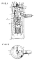
- 1 is a cylindrical body. On the axial line of the body 1, a cartridge piercing device 2, a valve pin 4 and an adjusting mechanism 5 are aligned.
- the cartridge piercing device 2 comprises a coupling screw 21 for a cartridge B and a needle block 23, which projects a needle 24 downward.
- the coupling screw 21 is formed at the inside of the lower end of a screw cylinder 22 screwed into the lower portion of the body 1.
- the needle block 23 is screwed into the screw cylinder 22 to be pressed against a step 26 which is at the lower end of a room 27, which is above the coupling screw and has a reduced diameter.
- a gas passage 25 is formed through the needle block 23 inclusive of the needle 24.
- a packing 28 is set on the surface of the needle block 23 around the needle 24.
- An expanded portion 29 at the upper end of the gas passage 25 is filled with a filter 30.
- the room 27 is connected by a more reduced passage 33 with a secondary space 11 over the screw cylinder 22.
- the valve pin 4 comprises a flange 41 at the lower end thereof, a passing portion 42 continuing from a shutting off portion 43 and a boundary portion.
- the flange 41 is loosely fitted in a passage 44, which is to be a primary pressure side of the gas and which is formed in a valve housing 45 fitted in the room 27 of the screw cylinder 22.
- the valve pin 4 is always urged upward by a spring 46 installed between the flange 41 and the filter 30, but can not move upward when the flange 41 comes into contact with a step 47 at the lower end of a reduced diameter passage 48, whose diameter is of the same length as that of the passage 33.
- the passage 48 is formed in the valve housing 45.
- the passage 33 and 44 are connected by the passage 48.
- An O-ring 49 is fitted in an annular groove 47' in the upper end of the valve housing 45 to surround the reduced diameter passage 48.
- the shutting off portion 43 fits closely to the O-ring and stops gas flow.
- the gas flows from the passage 48 into the passage 33.
- the boundary portion between the shutting off portion 43 and the passing portion 42 is favorably inclined so as not to damage the O-ring during the movement of the valve pin 4.
- the passing portion 42 may be provided with a flange 49' at the upper end thereof.
- the adjusting mechanism 5 can adjust the pressure of the gas from the cartridge.
- the adjusting mechanism 5 comprises a piston 51 which contacts with the top of the valve pin 4 at its lower plane and which fits freely slidably in the secondary space 11 in the body 1, a pressure adjusting spring 52 which is installed between the piston and an upper spring seat 53, a dial 54 which engages with the upper portion of the body 1 with the threads and is movable upward and downward by rotating, and a pressure adjusting screw 55 which engages with the threads of dial 54 and contacts with the top of the spring seat 53 at its lower end.
- the pressure adjusting spring 52 of the type is used, which the compression force becomes maximum when the dial 54 is rotated into the lowermost position, by removing the load by the pressure adjusting screw 55, and which loses the compression force when the dial 54 is rotated back uppermost.
- a spout 6 with an orifice 61 is provided to the secondary space 11.
- valve pin 4 When the valve pin 4 locates low, it must rise long stroke and compress heavily the pressure adjusting spring 52, to shut off the gas and reduce the pressure in the secondary space 11, then a large quantity of gas flows throught the orifice 61. On the contrary, when the valve pin 4 locates high, it shuts off the gas in its short stroke. Accordingly, the secondary pressure does not rise as in the former case, and a small quantity of gas flows through the orifice 61.
- Adjusting of the pressure is done by the pressure adjusting screw 55.
- the secondary pressure of the pressure reducing mechanism becomes high and quantity of flow increases. According to this function, a fixed quantity of flow is supplied controlled by the orifice 61 from the spout 6.
- One of the dial 54 and the body 1 is provided with a groove and the other with a pin which is fitted in the groove to decide a rotatable angle of the dial 54.
- the gas flow can be regulated from zero to a fixed quantity by the operation of the dial 54.
- the body 1 is provided with a pin 12 at the top thereof and the dial 54 is provided with an annular groove 56.
- the annular groove has a common center to one of a rotation of the top plate 57 of the dial 54 and into which the pin 12 is fitted.
- the pin 12 is inserted in a hole 14 opened at the top 13 of the body 1, after engaging the dial 54 on the body 1 and inserting the pin 12 through a hole 58 which passes through outward and is provided at a portion of the annular groove 56.
- the relation between the dial 54 and the valve pin 4 is as hereinafter described.
- 71 is a V-packing
- 72 is a push rod for the valve pin 4
- 73 is an O-ring.
- a mask or the like is connected to the spout 6 .
- the cartridge B is pierced by the piercing device.
- the gas flows in the passage 44 of the valve housing 45 of the valve pin 4 through the gas passage 25 of the needle block 23 of the primary pressure side. But the gas does not flows into the secondary space 11 as the shutting off portion 43 closely fits in the O-ring 49.
- the dial 54 is rotated downward, the piston 51 is pressed down and the valve pin 4 is also pressed down against the spring 46.
- the shutting off portion 43 of the valve pin 4 parts from the O-ring 49 and faces the passage 42, the gas flows into the secondary space 11 and is emitted reduced its pressure by the pressure adjusting spring 52 and fixed its quantity of flow through the spout 6.
- the gas emitted may be inhaled.
- the piston 51 moves upward compressing the spring 52.
- the valve pin 4 is also pressed up, and the shutting off portion 43 of which closely fits to the O-ring 49. So the gas stops and the pressure in the space 11 is reduced. Therefore the piston 51 falls again and presses the valve pin 4 downward, then the gas begin flowing.
- the dial 54 is used. When the dial 51 is rotated downward, the position of the piston 51 moves downward. Then the secondary pressure of the pressure adjusting mechanism rises and quantity of flow increases. The dial 54 being backed, the secondary pressure of the pressure adjusting mechanism falls and quantity of flow is decreased.
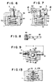
- Figures 3 to 5 show a modification of the packing 28 shown in Figure 1.
- the packing 28 comprises an O-ring portion 28a and a flange portion 28b.
- the flange portion 28b is less in thickness than the diameter of the O-ring portion in section and is made in one body with the O-ring portion 28a.
- the flange portion 28b also projects outwardly at right angles with the axial line of the O-ring portion 28b.
- the packing 28 is made of elastic material such as rubber, plastics, etc.
- the O-ring 31 may be omitted.
- the body 1 is made thick at its medium portion and the screw cylinder 22 is formed like as a nut.
- the packing 28 is fixed at its flange portion 28b between the lower face of the needle block 23 and the top of the screw cylinder 22.
- Figures 6 to 12 show embodiments of repective mechanisms to operate the valve pin 4.
- emission of gas is done by means of a push button or a lever
- gripping of the body and emitting operation can be done by one hand.
- a push button 81 is used for operating the valve pin 4 (not shown ) instead of the dial 54 in Figure 1. Also the function by the pressure adjusting screw 55 is replaced by a dial 82 and a set screw 83.
- the pressure adjusting spring 52 of such a type is employed, as a compressive force becomes maximum when the push button 81 moves lowermost and one becomes zero when uppermost.
- the push button 81 and the spring seat 53 may be made in one body.
- the valve pin 4 reaches at its lowermost position. Accordingly, high pressure is necessary to move the valve pin 4 to shut off the gas, so that a large quantity of the gas flows out.
- the valve pin shuts off the gas even its short upward movement, by a comparatively low pressure, so that a small quantity of the gas flows out.
- Figures 7 and 8 show a type of a lever.
- a bearing 84 is provided, and a lever 86 is pivoted at its one end by a pin 85. The other end of the lever 86 extends towards the opposite side of the top of the body 1 across the center thereof.
- a screw plug 87 is screwed in the upper end of the body 1, and the push button 81 is is loosely fitted in the plug 87. The upper end of the push button 81 is in contact with the lower plane of the lever 86. The fixing of the screw plug 87 is done by the set screw 83.
- the push button 81 is pushed in by means of the lever 86 instead of pushing directly the push button 81 as shown in Figure 6.
- the lever 86 As the principle of a lever is applied and a free end of the lever 86 reaches over the side of the body 1, the operation of the inhaler becomes easy.
- Figures 9 and 10 show a modification of a type of a push button, in which the push rod protrudes outwardly from the side of the body 1.
- 88 is an adjust pin which is screwed in the side of the body 1 and which can adjust its axial position. By adjusting the axial direction a movable area d of the push rod 81 can be settled.
- the push rod 81 is pushed left in Figure 9 till its end 89 comes into contact with the inner end of the adjust pin 88.
- a ball 91 fitting in a notch 90 is pressed downwardly by an inclined plane thereof, and the spring seat 53 moves downward till a certain portion.
- FIG 11 shows a cam lever type embodiment.
- the gas supply can be continued.
- 95 is a bearing formed on the dial 54, and the bearing 95 carries swingably a cam lever 96 by means of a pin 97.
- cams 96a and 96b are formed.
- the cam 96a engages the upper end of a protrusion 53a of the spring seat 53, to move the spring seat 53 upward or downward during the swinging motion of the cam lever 96.
- the cam 96b continues from the end of the cam 96a and locks the spring seat 53 when it engages the upper end of the protrusion 53a.
- the spring seat 53 moves downward, and at last the cam lever 96 stops by the engagement of the upper end of the protrusion 53a with the cam 96b.
- Figure 12 is a modification of a push button type.
- a cavity 98 is formed in the top 1a of the body 1 and in the cavity 98 liquid L is charged.
- the push button 81 is fitted in the cavity 98 from the upside, and the cavity 98 is open at its lower end to the spring seat 53.
- the push button 81 and the spring seat 53 are provided with seal members 99 and 100, respectively.
- An area to contact with the liquid L of the push button 81 is less than that of the spring seat 53. Thus the force necessary for pushing the push button 81 can be varied.
- a spring 101 to urge the push button is installed between the top 1a and a flange 102 of the push button 81. If a receiver is provided, the push button 81 can be fitted up at any place, and it is easy to go up the function of operation.
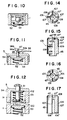
- Figures 13 to 17 are respective embodiments in which, at least when the gas is flowing, a primary gas pressure acts at the same time on both sides of the sealing member by providing a leader to the valve housing.
- One of the sides is a sealing side co-operative with the valve pin and the other is the opposite side. This balances the pressures which act on both sides of the sealing member and resists its deformation, thus the unity of flow of the gas is done.
- the valve housing 45 is provided with a leader 105 which passes to the passage 44 at one end and to an annular groove 47' for the seal member 49 at the other.
- FIGs 13 to 15 show an embodiment of the leader 105.
- the leader 105 consists of a lateral hole 106, a vertical groove 107 and a lateral groove 108.
- the lateral hole 106 is provided radially at the medium of the valve housing 45 and the passage 44 is connected to the outside by the lateral hole 106.
- the vertical groove 107 a also provided in the outer face of the valve housing 45, and it is connected at its lower end to the lateral hole 106 and reaches at the upper end of the valve housing 45.
- the lateral groove 108 is provided radially in the upper portion of the valve housing 45, and its outer end connected to the vertical groove 107 and its inner end to the annular groove 47'.
- the primary gas pressure acts on the side 49' of the seal member 49, which takes charge of opening or closing the gas passage. Also, the primary gas pressure acts on the side 49" opposite to the side 49' of the seal member through the leader 105. As this, the primary gas pressure acts on both sides 49' and 49" of the seal member 49, and the balance between both pressures is obtained. Therefore, even if the pressure which acts on the side 49' of the seal member 49 varies, deformation of the side 49' toward the side 49" can be restrained. Accordingly, a clearance between the passing portion 42 of the valve pin 4 and the side 49' of the seal member 49 is kept constant, so the gas flows in a fixed quantity.
- An annular groove 109 is provided connected to the outer end of the lateral hole 106 in the periphery of the valve housing 45, and the vertical grooves 107 which are connected to the annular groove 109 are equally spaced. Further, the upper ends of the vertical grooves 107 are connected to the annular groove 47' through the lateral grooves 108, respectively. In such an assembly, the seal member 49 is to be pressed equally, and it becomes more certain to check changing of the clearance as a passage.
- the valve housing can be manufactured easily.
- Figures 16 and 17 are the cases where the lateral hole 106 is omitted.
- the vertical groove 107 in the periphery is provided in full length of the valve housing 45.
- the radial groove 108 and also a radial groove 106' are provided connected to the vertical groove 107, respectively.
- a cartridge piercing device, a valve pin and an adjusting mechanism for a secondary pressure being aligned on the axial line of a cylindrical body, the inhaler becomes small and easy as a whole for carrying and using. Further, the adjusting mechanism being used as an adjuster for pressure and quantity of flow, the assembly becomes simple and the operation becomes easy. Thus according to the present invention there are many remarkable effects.
Landscapes
- Engineering & Computer Science (AREA)
- Health & Medical Sciences (AREA)
- Life Sciences & Earth Sciences (AREA)
- Animal Behavior & Ethology (AREA)
- Anesthesiology (AREA)
- Biomedical Technology (AREA)
- Heart & Thoracic Surgery (AREA)
- Hematology (AREA)
- Emergency Medicine (AREA)
- Pulmonology (AREA)
- General Health & Medical Sciences (AREA)
- Public Health (AREA)
- Veterinary Medicine (AREA)
- Mechanical Engineering (AREA)
- General Engineering & Computer Science (AREA)
- Control Of Fluid Pressure (AREA)
Claims (10)
- Tragbares Sauerstoffinhaliergerät, das auf der Achse eines zylindrischen Körpers (1)
eine Kartuschenzugriffsvorrichtung (2),
und ein Ventilgehäuse (45) mit einem Gasdurchgang (44) aufweist, der einen ersten und einen zweiten Raum auf jeder Seite einer Ventilnadel (4) verbindet, die beweglich in den Durchgang (44) eingesetzt ist und die einen Verschlußteil (43) hat, der unter dem Druck einer Feder (46) und eines Gases dazu tendiert, den Durchgang (44) mit einer mitwirkenden Seite (49') eines Dichtgliedes (49) abzuschließen, wobei ein Verstellmechanismus (5) für den zweiten Druckraum (11), an seinem einen Ende ein Ende der Ventilnadel (4) im zweiten Raum (11) berührt, dieser zweite Raum über eine Öffnung (61) mit einer Tülle (6) verbunden ist und die Strömungsmenge des Gases durch die Öffnung (61) durch Verändern des zweiten Druckes mit dem Verstellmechanismus (5) verstellbar ist, dadurch gekennzeichnet, daß
die Kartuschenzugriffsvorrichtung (2), eine Nadel (24) zum Durchstechen der Kartusche und eine Dichtung (28) aufweist, welche die Nadel (24) umgibt, das Ventilgehäuse (45) in dieser Kartuschenzugriffsvorrichtung (2) angeordnet ist und ein Kanal (105) den ersten Gasdruckraum mit der Seite (49") des Dichtgliedes (49) gegenüber der mitwirkenden Seite (49') verbindet, wobei die Gegenseite (49") so dem ersten Gasdruck unterworfen ist, daß der Gasdruck auf das Dichtglied (49) ausgeglichen wird, wenn das Ventil offen ist. - Tragbares Sauerstoffinhaliergerät nach Anspruch 1, wobei der Kanal (105) in das Ventilgehäuse (45) gekerbt ist.
- Tragbares Sauerstoffinhaliergerät nach Anspruch 1 oder 2, bei dem die Dichtung (28) einen O-Ringteil (28a) und einen Flanschteil (28b) aufweist, der eine geringere Dicke hat als der Durchmesser des O-Ringteiles im Querschnitt, der in einem Teil mit dem O-Ringteil (28a) gemacht ist und der nach außen im rechten Winkel zur Achse des O-Ringteiles (28a) übersteht.
- Tragbares Sauerstoffinhaliergerät nach einem der vorhergehenden Ansprüche, bei dem der Verstellmechanismus (5) einen Kolben (51), der verschiebbar in den zweiten Druckraum (11) eingepaßt ist und eine untere Oberfläche hat, die mit ihrer unteren Ebene die Spitze der Ventilnadel (4) berührt, eine Druckeinstellfeder (52), die zwischen dem Kolben (51) und einem oberen Federsitz (53) angebracht ist, und einen Auslöser (5) für die Ventilnadel (4), der am oberen Teil des zylindrischen Körpers (1) angebracht ist und auf den Kolben (51) über den Federsitz (53) wirkt, aufweist.
- Tragbares Sauerstoffinhaliergerät nach Anspruch 4, bei dem der Auslöser (5) von einer Einstellscheibe (54), die auf drehbare Art auf den oberen Teil des zylindrischen Körpers (1) geschraubt ist, und einer Druckeinstellschraube (55) gebildet wird, die in die Einstellscheibe (54) geschraubt ist, um den Federsitz (53) zu berühren und den zweiten Druck einzustellen, wobei eines der aus Einstellscheibe (54) und Körper (1) bestehenden Teile mit einer Rille (56) und das jeweils andere Teil mit einem Stift (12) versehen ist, der verschiebbar in die Rille (56) eingepaßt ist, um einen Drehwinkel der Einstellscheibe (54) festzusetzen, und wobei das Gas stufenlos von null bis zum Maximum reguliert werden kann, indem der Stift (12) in der Rille (56) von einem Ende zum anderen Ende der Rille (56) bewegt wird.
- Tragbares Sauerstoffinhaliergerät nach Anspruch 4, bei dem der Auslöser (5) von einer Einstellscheibe (82), die auf drehbare Art auf den oberen Teil des zylindrischen Körpers (1) geschraubt ist, um den zweiten Druck einzustellen, und einem Druckknopf (81), der durch die Einstellscheibe (82) geht, um den Federsitz (53) hineinzudrücken, um das Inhaliergerät an- und auszuschalten, gebildet wird.
- Tragbares Sauerstoffinhaliergerät nach Anspruch 4, bei dem der Auslöser (5) von einem Hebel, der drehbar auf einem Lagerteil (84) über das obere Ende des Körpers (1) hervorstehend angebracht ist, und einem Druckknopf (81), der beweglich in einem Schraubstöpsel (87) ist, welcher fest in den oberen inneren Endteil des Körpers (1) geschraubt ist, und der mit seinem oberen Ende den Hebel (86) und mit seinem unteren Ende den Federsitz (53) berührt, gebildet wird.
- Tragbares Sauerstoffinhaliergerät nach Anspruch 4, bei dem der Auslöser (5) von einer Stößelstange (81), die seitwärts über die Achse des Körpers (1) hervorsteht und die eine Mitnehmerkerbe (90) hat, um den Federsitz (53) mittels eines Balles zu drücken, und einem Einstellstift (88) gebildet ist, der in die Seitenwand des Körpers (1) geschraubt und in derselben Achse wie die Stößelstange ausgerichtet ist, und dessen inneres Ende in seiner axialen Richtung verstellbar ist, um den Hub der Stößelstange (81) einzustellen.
- Tragbares Sauerstoffinhaliergerät nach Anspruch 4, bei dem der Auslöser (5) von einem Mitnehmerhebel (96) und einer Einstellscheibe (54) gebildet wird, wobei der Mitnehmerhebel ein Profil hat, das aus zwei Abschnitten besteht, von denen einer während einer Schwingbewegung des Mitnehmerhebels (96) einen nach oben hervorstehenden Teil (53a) des Federsitzes (53) herunterdrückt und der andere den nach oben hervorstehenden Teil (53a) in seiner niedrigsten Lage sperrt, und der Mitnehmerhebel (96) drehbar auf einem Lagerteil (95) aufgebracht ist, das über das obere Ende der Einstellscheibe (54) vorsteht, und die Einstellscheibe auf das obere Ende des Körpers (1) geschraubt ist.
- Tragbares Sauerstoffinhaliergerät nach Anspruch 4, bei dem der Auslöser (5) von einem Druckknopf (81) und einer Einstellscheibe (54) gebildet wird, welche auf einen oberen Teil (la) des Körpers (1) geschraubt ist, wobei der Druckknopf (81) durch die Einstellscheibe (54) in eine Aushöhlung (98) in diesem oberen Teil paßt, die Aushöhlung (98) von Dichtteilen (99, 100) am Druckknopf (81) und am Federsitz (53) flüssigkeitsdicht gehalten wird und mit Flüssigkeit gefüllt ist und der Druckknopf (81) durch die Einrichtung einer Druckfeder (101), die zwischen dem oberen Teil (1a) und einem Flansch (102) des Druckknopfes (81) angebracht ist, eine Bestrebung hat, sich nach oben zu bewegen.
Applications Claiming Priority (6)
| Application Number | Priority Date | Filing Date | Title |
|---|---|---|---|
| JP7826485A JPS61238250A (ja) | 1985-04-15 | 1985-04-15 | 軽便型酸素補吸器 |
| JP78264/85 | 1985-04-15 | ||
| JP154352/85 | 1985-10-11 | ||
| JP1985154352U JPH0318778Y2 (de) | 1985-10-11 | 1985-10-11 | |
| JP1985176841U JPH0216767Y2 (de) | 1985-11-19 | 1985-11-19 | |
| JP176841/85 | 1985-11-19 |
Publications (3)
| Publication Number | Publication Date |
|---|---|
| EP0198708A2 EP0198708A2 (de) | 1986-10-22 |
| EP0198708A3 EP0198708A3 (en) | 1988-06-29 |
| EP0198708B1 true EP0198708B1 (de) | 1991-06-12 |
Family
ID=27302661
Family Applications (1)
| Application Number | Title | Priority Date | Filing Date |
|---|---|---|---|
| EP19860302792 Expired EP0198708B1 (de) | 1985-04-15 | 1986-04-15 | Tragbares Sauerstoffinhalationsgerät |
Country Status (2)
| Country | Link |
|---|---|
| EP (1) | EP0198708B1 (de) |
| DE (1) | DE3679701D1 (de) |
Cited By (2)
| Publication number | Priority date | Publication date | Assignee | Title |
|---|---|---|---|---|
| CN103990217A (zh) * | 2013-02-17 | 2014-08-20 | 陈霞 | 氧气闷孔减压阀吸入器 |
| TWI824942B (zh) * | 2023-02-24 | 2023-12-01 | 長庚學校財團法人長庚科技大學 | 緩釋型氣霧吸入器省力裝置 |
Families Citing this family (10)
| Publication number | Priority date | Publication date | Assignee | Title |
|---|---|---|---|---|
| IT216627Z2 (it) * | 1989-05-31 | 1991-09-17 | Mentasti Granelli Bruno | Accessorio automobilistico contro l'incipiente sonnolenza del conducente. |
| DE69413989T2 (de) * | 1993-08-18 | 1999-04-08 | Fisons Plc, Ipswich, Suffolk | Inhalator mit atemstromregelung |
| GB2306214A (en) * | 1994-12-20 | 1997-04-30 | Airbag Protection Systems Ltd | A vehicle air bag system |
| EP1757321A3 (de) | 1999-07-12 | 2007-11-28 | Capnia Incorporated | Verfahren und Anordnung zur Behandlung von Kopfschmerzen, Rhinitis und anderen Leiden |
| JP4932109B2 (ja) | 1999-07-12 | 2012-05-16 | キャプニア インコーポレイテッド | 頭痛、鼻炎及び他のありふれた病気を治す方法及び装置 |
| US20060172017A1 (en) | 1999-11-08 | 2006-08-03 | Capnia, Incorporated | Methods and apparatus for the enhanced delivery of physiologic agents to tissue surfaces |
| US20070039615A1 (en) | 1999-11-08 | 2007-02-22 | Capnia, Incorporated | Methods and apparatus for treating rhinitis |
| CN111920498B (zh) * | 2018-02-05 | 2021-07-02 | 安晓娜 | 一种可调压的助产器 |
| CN111408009B (zh) * | 2019-11-01 | 2024-06-04 | 北京毅安峰技术有限公司 | 一种带电子开关的蒸发器刻度盘组件 |
| CN111678040B (zh) * | 2020-06-12 | 2024-08-13 | 中煤科工集团沈阳研究院有限公司 | 一种自动苏生器用新型减压装置及减压方法 |
Family Cites Families (4)
| Publication number | Priority date | Publication date | Assignee | Title |
|---|---|---|---|---|
| GB971161A (en) * | 1960-02-03 | 1964-09-30 | British Oxygen Co Ltd | Control valve appliances for dispensing pressure fluid |
| GB1039528A (en) * | 1963-08-14 | 1966-08-17 | British Oxygen Co Ltd | Fluid pressure regulating device |
| GB1069917A (en) * | 1963-11-21 | 1967-05-24 | British Oxygen Co Ltd | Fluid regulating valve mechanism |
| US3776227A (en) * | 1972-01-31 | 1973-12-04 | I Pitesky | Portable hyperventilation relieving device |
-
1986
- 1986-04-15 DE DE8686302792T patent/DE3679701D1/de not_active Expired - Lifetime
- 1986-04-15 EP EP19860302792 patent/EP0198708B1/de not_active Expired
Cited By (2)
| Publication number | Priority date | Publication date | Assignee | Title |
|---|---|---|---|---|
| CN103990217A (zh) * | 2013-02-17 | 2014-08-20 | 陈霞 | 氧气闷孔减压阀吸入器 |
| TWI824942B (zh) * | 2023-02-24 | 2023-12-01 | 長庚學校財團法人長庚科技大學 | 緩釋型氣霧吸入器省力裝置 |
Also Published As
| Publication number | Publication date |
|---|---|
| DE3679701D1 (de) | 1991-07-18 |
| EP0198708A3 (en) | 1988-06-29 |
| EP0198708A2 (de) | 1986-10-22 |
Similar Documents
| Publication | Publication Date | Title |
|---|---|---|
| EP0198708B1 (de) | Tragbares Sauerstoffinhalationsgerät | |
| US4453567A (en) | Valve assembly | |
| AU692526B2 (en) | Single handle mixing valve with an improved ball valve | |
| US4195656A (en) | Orifice device with safety shut-off for pressure regulators | |
| US4492247A (en) | Sequencing valve | |
| US7237570B2 (en) | Gas cylinder dispensing valve | |
| US4231549A (en) | Valve stem and valve disc connection for a diaphragm valve | |
| US6588724B2 (en) | On-off valves for high pressure fluids | |
| WO1996001445A1 (en) | A fluid pressure regulator | |
| KR20020042638A (ko) | 서지 방지 장치 | |
| KR20060007373A (ko) | 조정 가능한 정지 수단이 구비된 밸브 | |
| US3240223A (en) | Fluid pressure regulator | |
| JPH0524391B2 (de) | ||
| EP1715230B1 (de) | Fluidsteuerung | |
| CN212327145U (zh) | 一种直动式医用需求阀 | |
| CN116293013B (zh) | 压力调节阀 | |
| US4905730A (en) | Override check valve | |
| AU6985698A (en) | Liquid forced-feed apparatus | |
| US20060037465A1 (en) | Hydraulic machine | |
| US6202682B1 (en) | Pressure regulator with selector control | |
| NL8503446A (nl) | Stuur-afsluiter. | |
| KR102667662B1 (ko) | 복합밸브 | |
| US3411523A (en) | Pressure regulator | |
| CN111467639B (zh) | 一种直动式医用需求阀 | |
| EP1429061A1 (de) | Selbstschliessender Hahn mit einstellbarer Abgabezeit |
Legal Events
| Date | Code | Title | Description |
|---|---|---|---|
| PUAI | Public reference made under article 153(3) epc to a published international application that has entered the european phase |
Free format text: ORIGINAL CODE: 0009012 |
|
| AK | Designated contracting states |
Kind code of ref document: A2 Designated state(s): DE FR GB IT NL |
|
| PUAL | Search report despatched |
Free format text: ORIGINAL CODE: 0009013 |
|
| AK | Designated contracting states |
Kind code of ref document: A3 Designated state(s): DE FR GB IT NL |
|
| 17P | Request for examination filed |
Effective date: 19881130 |
|
| 17Q | First examination report despatched |
Effective date: 19900504 |
|
| GRAA | (expected) grant |
Free format text: ORIGINAL CODE: 0009210 |
|
| AK | Designated contracting states |
Kind code of ref document: B1 Designated state(s): DE FR GB IT NL |
|
| ITF | It: translation for a ep patent filed | ||
| REF | Corresponds to: |
Ref document number: 3679701 Country of ref document: DE Date of ref document: 19910718 |
|
| ET | Fr: translation filed | ||
| PLBE | No opposition filed within time limit |
Free format text: ORIGINAL CODE: 0009261 |
|
| STAA | Information on the status of an ep patent application or granted ep patent |
Free format text: STATUS: NO OPPOSITION FILED WITHIN TIME LIMIT |
|
| 26N | No opposition filed | ||
| REG | Reference to a national code |
Ref country code: GB Ref legal event code: IF02 |
|
| PGFP | Annual fee paid to national office [announced via postgrant information from national office to epo] |
Ref country code: FR Payment date: 20050325 Year of fee payment: 20 |
|
| PGFP | Annual fee paid to national office [announced via postgrant information from national office to epo] |
Ref country code: GB Payment date: 20050404 Year of fee payment: 20 |
|
| PGFP | Annual fee paid to national office [announced via postgrant information from national office to epo] |
Ref country code: IT Payment date: 20050415 Year of fee payment: 20 |
|
| PGFP | Annual fee paid to national office [announced via postgrant information from national office to epo] |
Ref country code: NL Payment date: 20050430 Year of fee payment: 20 |
|
| PGFP | Annual fee paid to national office [announced via postgrant information from national office to epo] |
Ref country code: DE Payment date: 20050531 Year of fee payment: 20 |
|
| PG25 | Lapsed in a contracting state [announced via postgrant information from national office to epo] |
Ref country code: GB Free format text: LAPSE BECAUSE OF EXPIRATION OF PROTECTION Effective date: 20060414 |
|
| PG25 | Lapsed in a contracting state [announced via postgrant information from national office to epo] |
Ref country code: NL Free format text: LAPSE BECAUSE OF EXPIRATION OF PROTECTION Effective date: 20060415 |
|
| REG | Reference to a national code |
Ref country code: GB Ref legal event code: PE20 |
|
| NLV7 | Nl: ceased due to reaching the maximum lifetime of a patent |
Effective date: 20060415 |