EP0198929A1 - Appareil pour l'enrobage - Google Patents
Appareil pour l'enrobage Download PDFInfo
- Publication number
- EP0198929A1 EP0198929A1 EP85104715A EP85104715A EP0198929A1 EP 0198929 A1 EP0198929 A1 EP 0198929A1 EP 85104715 A EP85104715 A EP 85104715A EP 85104715 A EP85104715 A EP 85104715A EP 0198929 A1 EP0198929 A1 EP 0198929A1
- Authority
- EP
- European Patent Office
- Prior art keywords
- coating
- baffle means
- coating pan
- coating apparatus
- set forth
- Prior art date
- Legal status (The legal status is an assumption and is not a legal conclusion. Google has not performed a legal analysis and makes no representation as to the accuracy of the status listed.)
- Withdrawn
Links
Images





Classifications
-
- A—HUMAN NECESSITIES
- A23—FOODS OR FOODSTUFFS; TREATMENT THEREOF, NOT COVERED BY OTHER CLASSES
- A23G—COCOA; COCOA PRODUCTS, e.g. CHOCOLATE; SUBSTITUTES FOR COCOA OR COCOA PRODUCTS; CONFECTIONERY; CHEWING GUM; ICE-CREAM; PREPARATION THEREOF
- A23G3/00—Sweetmeats; Confectionery; Marzipan; Coated or filled products
- A23G3/02—Apparatus specially adapted for manufacture or treatment of sweetmeats or confectionery; Accessories therefor
- A23G3/20—Apparatus for coating or filling sweetmeats or confectionery
- A23G3/26—Apparatus for coating by tumbling with a liquid or powder, spraying device-associated, drum, rotating pan
-
- A—HUMAN NECESSITIES
- A61—MEDICAL OR VETERINARY SCIENCE; HYGIENE
- A61J—CONTAINERS SPECIALLY ADAPTED FOR MEDICAL OR PHARMACEUTICAL PURPOSES; DEVICES OR METHODS SPECIALLY ADAPTED FOR BRINGING PHARMACEUTICAL PRODUCTS INTO PARTICULAR PHYSICAL OR ADMINISTERING FORMS; DEVICES FOR ADMINISTERING FOOD OR MEDICINES ORALLY; BABY COMFORTERS; DEVICES FOR RECEIVING SPITTLE
- A61J3/00—Devices or methods specially adapted for bringing pharmaceutical products into particular physical or administering forms
- A61J3/005—Coating of tablets or the like
Definitions
- This invention relates to a coating apparatus, more particularly, a coating apparatus for coating pharmaceutical or food tablets or the like with a layer of other medical composition or sugar etc., which apparatus includes a rotatable coating pan, the side wall of which has a ventilating area or areas for feeding dry air as a ventilating and drying mechanism.
- a coating material such as a film liquid or a sugar solution
- a material to be coated such as tablets or a granular raw material
- the coating material is dried
- a method wherein the tablets as being the material to be coated are tumbled in a coating pan by the rotation of the coating pan, while heated air is blown onto the surface of a bed of the tablets to dry the tablets.
- the tablets in the inside and lower zones of the bed are insufficiently dried because the heated gas cannot reach such zones. Therefore, it takes long time to dry all of the tablets in the coating pan, and it is difficult to dry the tablets uniformly.
- a coating apparatus shown in Fig. 1 and 2 which is disclosed in the Japanese Patent Publication No. 38713/1975.
- This coating apparatus is provided with a ventilating and drying mechanism comprised of perforated areas 2 for ventilating air, arranged axially in a plurality of circumferential positions of whole circumference of a rotatable coating pan or rotatable drum 1, an air supply conduit 3, an exhaust or suction duct 4, and exhaust conduit 5.
- the heated air blown into the coating pan 1 from the air supply conduit 3 is blown onto tablets 6 tumbled in the coating pan 1, and after passing through the bed of the tablets 6, the heated air is exhausted from the exhaust conduit 5 via the perforated area 2 and the exhaust duct 4.
- this coating apparatus is used as an excellent coating apparatus in practice, because, in this coating apparatus, the heated gas can contact uniformly with the tablets 6 not only in the surface zone but also in the inside and lower zones of the bed thereof while passing through the bed of the tablets, the heat efficiency is very high, and it is possible to obtain homogeneous product dried with overall uniformity and with high productivity.
- this coating apparatus it is possible to perform coating operation efficiently and in low cost, using an aqueous coating solution wherein coating material is dissolved or dispersed in the water (in this connection, refer to the Japanese Patent Publication No. 5491/1980).
- the reference numeral 7 is a rotary shaft for rotating the coating pan 1
- 8 is a motor for driving the rotary shaft 7 via transmission means 9 such as a belt or a chain
- 10 is a cylindrical portion which forms a charging opening through which tablets 6 to be coated are charged into the coating pan 1
- 11 is a cover for the cylindrical portion 10.
- the ventilating apertures are blocked, the smooth flow of the heated gas is prevented to produce non-uniform ventilation, and the pressure loss of the ventilation system becomes increased or changed to make the coating operation instable. Further, it takes longer time for drying because of the reduction of the heat efficiency.
- the present invention has been developed to eliminate the above-described drawbacks of the prior art and has as its object the provision of a coating apparatus which can not only prevent the leak of powdery material from the ventilating areas of the coating pan, but also smooth the flow of the raw material to be coated, further, prevent damages thereof and occurrence of noises therefrom and secure the rate of charge.
- the coating apparatus according to the present invention can smooth the flow of the material to be coated, improve the effect of agitating and mixing, and control damages of the material to be coated and occurrence of noises.
- Fig. 3 is a partial side sectional view generally showing one embodiment of the coating apparatus according to the present invention
- Fig. 4 is a general front sectional view of the apparatus shown in Fig. 3
- Fig. 5 is an enlarged partial sectional view of the portion A of Fig. 4.
- the rotatable coating pan 1 has a substantially conical side elevational shape.
- a baffle or scoop means 12 having a tapered shape from the trailing edge 12b to the leading edge 12a relative to a rotational direction R of the coating pan 1 at a position to cover entirely or partially each perforated area 2 of the coating pan 1.
- the baffle means 12 scoops the material to be coated, such as the tablets 6, other-granular raw material or the like tumbled along the inner wall surface of the coating pan 1 due to the rotational movement of the coating pan 1 from the leading edge 12a to the trailing edge 12b, whereby the baffle means smoothes the flow of the tablets 6, improves the mixing and agitating of the tablets 6 and prevents the rate of charge from being reduced.
- the baffle means 12 is constructed such that the leading edge 12a has a pointed tapered shape relative to the rotational direction R of the coating pan 1, the trailing edge 12b has a height H, to which the minimum height of the leading edge 12a is gradually increased along an inclined side edge 12c, and has a width W, to which the minimum width of the leading edge 12a is gradually increased, whereby the baffle means 12 is inclined both in the vertical and the horizontal directions.
- the bottom face of the side portion of the baffle means 12 is fixed to the inner wall surface of the coating pan 1 by welding etc. from the leading edge 12a to the trailing edge 12b.
- This baffle means 12 is formed at the trailing edge 12b thereof with a triangular ventilating opening 13, which is communicated with ventilating apertures 2a of the perforated area 2 formed in the wall surface of the coating pan 1, so that the flow of the gas 14 can flow into and out of the coating pan 1.
- a ventilating member 15 formed of a mesh for ventilating the leak of the tablets 6 or the like is provided at the position of the ventilating opening 13 of the baffle means 12.
- the dimensions of the baffle means 12 in this embodiment there are generally adopted the following ranges, however, the dimensions may be further decreased.
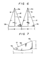
- the height H of the baffle means 12 (Refer to Fig. 7) is from one-third to one-twentieth of the inner diameter of the coating pan 1
- the length L (Refer to Fig. 7) is from one-fourth to one-fortieth of the inner diameter of the coating pan 1
- the width W (Refer to Fig. 6) is from one-half to one-twentieth of the axial length of the coating pan 1
- an angle ⁇ 1 of the leading edge 12a in the rotational direction of the baffle means 12 is from 20° to 120°
- an angle of inclination 8 2 of the side edge 12c is from 10° to 90°.
- baffle means 12 are arranged integrally and in parallel to each other, however, three baffle means 12 may be arranged integrally and in parallel to one another, or a single baffle means may be used.
- baffle means 12 are provided for the perforated areas 2 formed at four positions arranged in the circumferential direction of the coating pan 1, respectively.
- the cover 11 of the cylindrical portion 10 of the coating pan 1 is opened, and the tablets 6 as being the raw material to be coated are charged into the coating pan 1. Then, a desired coating solution is sprayed by a conventional spray mechanism, not shown, into the coating pan 1 through the cylindrical opening 10, and a layer of the coating material is formed on the tablets 6 tumbled along the inner wall surface of the coating pan 1 due to the rotational movement of the coating pan 1. Subsequently, the heated gas is blown into the coating pan 1 via the supply conduit 3, and flows through the bed of the tablets 6 coated with the coating material, and then, exhausted out of the coating pan 1 through the ventilating apertures 2a (Refer to Fig. 5) of the perforated area 2.
- the baffle means 12 are provided on the inner wall surface of the coating pan 1, the tablets 6 tumbled along the inner wall surface of the coating pan 1 by the rotary movement of the coating pan 1 are scooped or raised on the baffle means 12 at the leading edge 12a thereof, then, along the inclined side wall surface of the baffle means 12, and pushed to the side of the baffle means 12.
- the rate of occurrence of breakages at the time of polishing of the tablets 6 according to the present invention is by far lower than that in the prior art shown in Figs. 1 and 2 (indicated by solid lines in Fig. 11), thereby enabling to obtain highly satisfactory effect of preventing the tablets from being broken.
- the smooth movement of the tablets 6 in the coating pan 1 makes it possible to minimize the noises during the coating operation.
- the maximum rate of charge when it is determined to be 100% with no structure being present in the coating pan 1 as shown in Figs. 1 and 2, the maximum rate of charge is 95.5% according to the present invention, whereby the rate of charge is slightly decreased.
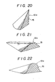
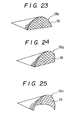
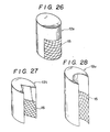
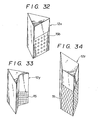
- Figs. 12 to 34 are perspective views showing various embodiments of the baffle means according to the present invention.
- the baffle means in an embodiment shown in Fig. 12 is of such an arrangement that there are provided integrally and in parallel to each other two baffle means 12d, each of which is tapered such as to be decreased in height and width from the trailing edge to the leading edge and has a generally semicircular shape in cross section, so that the outstanding effects of agitating and mixing, preventing the breakages and so on can be obtained.
- Fig. 13 there are integrally arranged two tapered and wave-shaped baffle means 12e.
- FIG. 14 shows a construction of a baffle means 12f of a curved-surfaced and tridimensional shape. In this case also, a satisfactory coating operation can be performed by the baffling action and scooping action by the baffle means 12f.
- baffle means 12x, 12y and 12z as shown in Figs. 32, 33 and 34 are hollow and have a regular triangular shape, a deformed triangular shape and a square shape, in the horizontal cross section, respectively.
- a ventilating member 15b has a construction of preventing the powder leak, which is made of a perforated plate.
- the present invention is not only applicable to the conical type coating apparatus, but also applicable to the coating apparatuses of a cylindrical type, an onion type, a pear type and the like.
- the present invention is applicable to various fields of the coating treatments of foods, feedstuffs, agricultural medicines, manures, toners etc. in addition to the pharmaceuticals such as the tablets in the above embodiments.
- the present apparatus may be used for granulation.
- each of said baffle means is at least partially increased in width from the leading edge to the trailing edge relative to the rotational direction of the coating pan, and has the ventilating opening communicated with the ventilating areas, so that the following outstanding combined effects can be achieved.
Landscapes
- Health & Medical Sciences (AREA)
- Chemical & Material Sciences (AREA)
- Life Sciences & Earth Sciences (AREA)
- Medicinal Chemistry (AREA)
- Polymers & Plastics (AREA)
- Food Science & Technology (AREA)
- Engineering & Computer Science (AREA)
- Pharmacology & Pharmacy (AREA)
- Animal Behavior & Ethology (AREA)
- General Health & Medical Sciences (AREA)
- Public Health (AREA)
- Veterinary Medicine (AREA)
- Medical Preparation Storing Or Oral Administration Devices (AREA)
- Glanulating (AREA)
Priority Applications (1)
| Application Number | Priority Date | Filing Date | Title |
|---|---|---|---|
| EP85104715A EP0198929A1 (fr) | 1983-12-21 | 1985-04-18 | Appareil pour l'enrobage |
Applications Claiming Priority (2)
| Application Number | Priority Date | Filing Date | Title |
|---|---|---|---|
| JP58241552A JPS60133838A (ja) | 1983-12-21 | 1983-12-21 | パンコ−チング装置 |
| EP85104715A EP0198929A1 (fr) | 1983-12-21 | 1985-04-18 | Appareil pour l'enrobage |
Publications (1)
| Publication Number | Publication Date |
|---|---|
| EP0198929A1 true EP0198929A1 (fr) | 1986-10-29 |
Family
ID=26096692
Family Applications (1)
| Application Number | Title | Priority Date | Filing Date |
|---|---|---|---|
| EP85104715A Withdrawn EP0198929A1 (fr) | 1983-12-21 | 1985-04-18 | Appareil pour l'enrobage |
Country Status (1)
| Country | Link |
|---|---|
| EP (1) | EP0198929A1 (fr) |
Cited By (5)
| Publication number | Priority date | Publication date | Assignee | Title |
|---|---|---|---|---|
| GB2194743B (en) * | 1986-09-02 | 1990-08-08 | Ceres Ets | Method and apparatus for film coating seed material |
| EP0545044A3 (en) * | 1991-11-27 | 1993-07-14 | Lorenz B. Dipl.-Ing. Bohle | Coating apparatus for lump products, particularly pills and tablets |
| DE102005020992B3 (de) * | 2005-05-03 | 2006-12-14 | Uhde Gmbh | Mehrstufige Coatingvorrichtung für Formkörper |
| KR101207973B1 (ko) | 2011-03-22 | 2012-12-04 | 주식회사 세종파마텍 | 약품 코팅기용 팬 |
| CN113995675A (zh) * | 2021-10-28 | 2022-02-01 | 徐海艳 | 一种成品率高的包衣机 |
Citations (1)
| Publication number | Priority date | Publication date | Assignee | Title |
|---|---|---|---|---|
| FR2533825A1 (fr) * | 1982-10-04 | 1984-04-06 | Freunt Ind Co Ltd | Dispositif d'enrobage de pastilles |
-
1985
- 1985-04-18 EP EP85104715A patent/EP0198929A1/fr not_active Withdrawn
Patent Citations (1)
| Publication number | Priority date | Publication date | Assignee | Title |
|---|---|---|---|---|
| FR2533825A1 (fr) * | 1982-10-04 | 1984-04-06 | Freunt Ind Co Ltd | Dispositif d'enrobage de pastilles |
Cited By (7)
| Publication number | Priority date | Publication date | Assignee | Title |
|---|---|---|---|---|
| GB2194743B (en) * | 1986-09-02 | 1990-08-08 | Ceres Ets | Method and apparatus for film coating seed material |
| EP0545044A3 (en) * | 1991-11-27 | 1993-07-14 | Lorenz B. Dipl.-Ing. Bohle | Coating apparatus for lump products, particularly pills and tablets |
| US5334244A (en) * | 1991-11-27 | 1994-08-02 | Bohle Lorenz B | Device for covering lumpy products, especially pills, pellets or tablets, with a coating material |
| DE102005020992B3 (de) * | 2005-05-03 | 2006-12-14 | Uhde Gmbh | Mehrstufige Coatingvorrichtung für Formkörper |
| KR101207973B1 (ko) | 2011-03-22 | 2012-12-04 | 주식회사 세종파마텍 | 약품 코팅기용 팬 |
| CN113995675A (zh) * | 2021-10-28 | 2022-02-01 | 徐海艳 | 一种成品率高的包衣机 |
| CN113995675B (zh) * | 2021-10-28 | 2023-11-03 | 广东先通药业有限公司 | 一种成品率高的包衣机 |
Similar Documents
| Publication | Publication Date | Title |
|---|---|---|
| US4640218A (en) | Tablet coating apparatus | |
| US4799449A (en) | Coating apparatus | |
| CA2977741C (fr) | Appareil et procede de calcination de gypse | |
| JP3349580B2 (ja) | パンコーティング装置 | |
| US7614359B2 (en) | Coating apparatus | |
| JP2004148292A (ja) | コーティング装置 | |
| JP4588349B2 (ja) | コーティング装置 | |
| DE2212985A1 (de) | Drageemaschine | |
| JP4271386B2 (ja) | 粉粒体処理装置 | |
| JP2007152224A (ja) | 粉粒体処理装置及びバッフル装置 | |
| CN201429303Y (zh) | 一种粉料搅拌干燥设备 | |
| CN108467179A (zh) | 一种处理明胶污泥的污泥干燥机 | |
| JP2001187115A (ja) | 粉粒体処理方法および装置 | |
| JP3741473B2 (ja) | 胴型乾燥装置 | |
| JPH0517488U (ja) | 粉粒体の間接加熱式回転乾燥機 | |
| JPH0434396Y2 (fr) | ||
| CN215063367U (zh) | 一种粉末涂料加工用原料烘烤炉 | |
| CN215597978U (zh) | 一种肥料颗粒用干燥装置 | |
| JPS5992016A (ja) | パンコ−チング装置 | |
| JPS5844948B2 (ja) | 加熱回転炉の内部逆送装置 | |
| JPS63661Y2 (fr) | ||
| JPH03258335A (ja) | グラスライニング製粉粒体混合乾燥機 | |
| JPH0577239U (ja) | コール・イン・チューブドライヤ | |
| JPS6397B2 (fr) | ||
| JPS5816115B2 (ja) | 横形円筒形熱交換器 |
Legal Events
| Date | Code | Title | Description |
|---|---|---|---|
| PUAI | Public reference made under article 153(3) epc to a published international application that has entered the european phase |
Free format text: ORIGINAL CODE: 0009012 |
|
| AK | Designated contracting states |
Kind code of ref document: A1 Designated state(s): CH DE FR GB IT LI NL |
|
| 17P | Request for examination filed |
Effective date: 19861223 |
|
| 17Q | First examination report despatched |
Effective date: 19880315 |
|
| STAA | Information on the status of an ep patent application or granted ep patent |
Free format text: STATUS: THE APPLICATION HAS BEEN WITHDRAWN |
|
| 18W | Application withdrawn |
Withdrawal date: 19890417 |
|
| R18W | Application withdrawn (corrected) |
Effective date: 19890417 |
|
| RIN1 | Information on inventor provided before grant (corrected) |
Inventor name: GOTOU, MASAKAZU Inventor name: MOTOYAMA, SHIMESU Inventor name: SAKUMA, YUTAKA Inventor name: SHIRAKAWA, HIROMU Inventor name: MAKINO, TAKAMOTO Inventor name: MIYATA, KATSUAKI |