EP0198962B1 - Dispositif de soupape pour un instrument médical - Google Patents
Dispositif de soupape pour un instrument médical Download PDFInfo
- Publication number
- EP0198962B1 EP0198962B1 EP85116608A EP85116608A EP0198962B1 EP 0198962 B1 EP0198962 B1 EP 0198962B1 EP 85116608 A EP85116608 A EP 85116608A EP 85116608 A EP85116608 A EP 85116608A EP 0198962 B1 EP0198962 B1 EP 0198962B1
- Authority
- EP
- European Patent Office
- Prior art keywords
- valve
- slits
- slit
- disk
- catheter
- Prior art date
- Legal status (The legal status is an assumption and is not a legal conclusion. Google has not performed a legal analysis and makes no representation as to the accuracy of the status listed.)
- Expired
Links
Images


Classifications
-
- A—HUMAN NECESSITIES
- A61—MEDICAL OR VETERINARY SCIENCE; HYGIENE
- A61M—DEVICES FOR INTRODUCING MEDIA INTO, OR ONTO, THE BODY; DEVICES FOR TRANSDUCING BODY MEDIA OR FOR TAKING MEDIA FROM THE BODY; DEVICES FOR PRODUCING OR ENDING SLEEP OR STUPOR
- A61M39/00—Tubes, tube connectors, tube couplings, valves, access sites or the like, specially adapted for medical use
- A61M39/02—Access sites
- A61M39/06—Haemostasis valves, i.e. gaskets sealing around a needle, catheter or the like, closing on removal thereof
- A61M39/0606—Haemostasis valves, i.e. gaskets sealing around a needle, catheter or the like, closing on removal thereof without means for adjusting the seal opening or pressure
Definitions
- This invention relates to medical instruments provided with valve means, and more particularly to a medical instrument suitable for use in a catheter introducer, a general catheter, a catheter with a balloon, an ectosomatic circulating device and the like.
- a catheter introducer for medical treatment as a means for introducing rod-like members such for example as a catheter for blood-vessel contrast and the like into a blood-vessel.
- a catheter introducer for medical treatment as a means for introducing rod-like members such for example as a catheter for blood-vessel contrast and the like into a blood-vessel.
- a main body of the introducer inserted therethrough with an expander is advanced into the blood-vessel through the guide wire, thereafter, the dilator together with the guide wire, and the catheter is guided into a path in a main body so as to be insertable into the blood-vessel.
- a catheter introducer for medical treatment 2 a main body, 3 a cap, and 4 a catheter.
- a first valve body 5 and a second valve body 6, which are made of an elastomeric material, are parallelly provided in a path 2A of the main body 2 in a manner to be clamped by the main body 2 and the cap 3.
- the first valve body 5 is provided at the central portion thereof with a round opening 5A, and makes it possible to prevent a blood leak under conditions where the catheter 4 is inserted into the path of the main body 2.
- the second valve body 6 is provided at the central portion there of with a slit 6A, and makes it possible to prevent a blood leak when the catheter 4 is not inserted through the path of the main body 2.
- a valve body assembly comprising the first valve body 5 and the second valve body 6, an outer diameter of the catheter 4 which is applicable is primarily fixed as commensurate to the round opening 5A formed on the first valve body.
- a blood leak cannot be prevented, and it becomes difficult to apply to a forward end flexing type catheter requiring a combination of the catheter introducer 1 with the guide wire.
- this valve body assembly consisting of the two valve bodies including the first valve body 5 and the second valve body 6, becomes complicated in construction.
- valve body assembly which includes a disc-shaped first valve body having an expandable opening, by which no materials are removed, and a tubular second valve body provided with a forward end portion having sealing lips which are pressed against each other.
- the valve body assembly being small in scope of expansion or contraction of the opening provided in the first valve body, cannot have tubular members of widely varied outer diameters inserted therethrough and held therein.
- the valve body assembly consisting of the two valve bodies including the first valve body and the second valve body, becomes complicated in construction.
- valve body having a first slit openable in one of the end faces and a second slit openable in the other of the end faces, the first slit and the second slit crossing each other in the valve body GB-A-2 135 899. Since this valve body is dispensed with a first valve 5 having ring-shaped disk as shown in Fig. 1, a catheter of various outer diameters can be applicable thereto without causing leakage of blood. However this valve body has a drawback in that it will take a relatively long time to restore its original closed status after the withdrawal of a catheter, so that a small amount of blood may leak out of the valve body. This tendency is more apparent when a catheter is left in the valve for a long period of time.
- a medical instrument for use in a catheter introducer which comprises two valves being arranged in parallel and adjacent to one another, one valve thereof having a small opening extending from the front surface to the back surface, the other having a slit being shaped like the mouth of an alligator at the tip of a conical cylindrical body. Neither the opening nor the slit of these valves are suited to provide a strong and prompt closing function, so that a certain amount of blood may leak out of each of the two valves at least upon withdrawal of a catheter therefrom.
- the first valve 16 and second valve 17 are respectively made of a flexible and elastomeric material including a synthetic rubber such as a silicone rubber, urethane rubber or a fluoro rubber, and a natural rubber, etc.
- the valve body 16 is formed therein in a suitable method with a first slit 18 openable to one of the end faces thereof and a second slit 19 openable to the other of the end faces thereof.
- the first slit 18 and the second slit 19 cross each other at the inside of the valve body 16.
- the term "cross” means that the slits are combined together alternately, whereby the slits formed from opposite end faces partially coincide with each other at the crossing portion, so that the rod-like members are insertable.
- the angle of crossing need not necessarily be a right angle. More specifically, the first slit 18 and the second slit 19 form a crossing portion 20 having a distance L.
- Fig. 6 is the explanatory view showing the direction (the direction of arrow) of deformation of the first slit 18 and the second slit 19 when the catheter 15 is inserted through the valve body 16.
- Fig. 7 is the explanatory view showing the shapes of openings in the first slit 18 and the second slit 19 when the catheter 15 is inserted through the valve body 16.
- valve body 16 is sliced into three characteristic portions in the axial direction thereof, including a portion having therein only the first slit 18, a portion having therein a crossing portion 20 and a portion having therein only the second slit 19, then there exist three portions 16A through 16C as shown in (1) of Fig. 6. If, in the valve body 16, three separate portions as shown at the 16A through 16C are merely superimposed on one another, then the directions of deformation of the slits 18 and 19 when the insertion is about to be made become ones as indicated by arrow marks in (2) of Fig. 6, and shapes of openings of the slits 18 and 19 after the insertion become ones shown in (1) of Fig. 7.
- valve body 16 is originally an integral body by itself, each of the sliced portions is subject to the influences from the other portions adjacent thereto, the directions of deformation of the slits 18 and 19, when the catheter 15 is about to be inserted, are continuously varied inside the valve body 16 along the axial direction thereof as indicated by arrow marks in (3) of Fig. 6, and the shapes of openings of the slits 18 and 19 after the insertion become ones shown in (2) of Fig. 7. More specifically, the surroundings of the catheter 15 inserted through the valve body 16 are continuously pressed by the slits 18 and 19 along the axial direction of the valve body 16 with no gaps being formed even when the outer diameter of the catheter 15 is comparatively small or comparatively large.
- a distance L formed by the crossing portion 20 between the first slit 18 and the second slit 19 is determined in accordance with the maximal outer diameter of the catheter 15 to be inserted into the valve body 16.
- the length of L should be 0.4 mm or more.
- Radial slit 21 (e.g., a Y-shaped slit) is formed in second valve 17, as shown in Fig. 8. Since second valve 17 is separated from first valve 16, when a bar-like member (e.g., a catheter) is inserted into slit 21, slit 21 is opened and turned over in the insertion direction of the member.
- a bar-like member e.g., a catheter
- Connecting portion 23 forming path 22 communicating with path 14 is molded integrally with medical instrument 10. If a heparin-containing normal saline solution is introduced into appliance 10, thrombus in path 14 or at the boundary between path 14 and catheter 15 can be prevented.
- a method of using medical instrument 10, which comprises a combination of first and second valves 16 and 17, will be described hereafter with reference to Figs. 9 and 10.
- a hollow needle in which an inner needle is inserted penetrates the skin and is introduced into a blood vessel.
- guide wire 31 is inserted into the hollow needle.
- one end of guide wire 31 remains indwelled in the blood vessel.
- extension device 32 which is inserted in path 14, is fitted to cover guide wire 31.
- the distal end portion of device 32 is guided along guide wire 31 and inserted into the blood vessel wall, thereby extending the hole in the blood vessel wall.
- flexible tube 13 of instrument 10 is introduced into blood vessel 33.
- slits 18 and 19 of first valve 16 do not reach the corresponding opposite end faces, they can provide high pressure resistance against blood pressure applied to an end face of valve 16 and maintain a tight seal without being deformed by the blood pressure.
- Catheter 15 is then introduced via opening 12A of cap 12, and penetrates through slits 18 and 19 of valve 16 and slit 21 of valve 17. Catheter 15 passes through main body 11, is guided to flexible tube 13, and then reaches vessel 33. When catheter 15 is inserted into path 14 of instrument 10, valve 16 is brought into surface contact with catheter 15 and forms a tight seal, thus preventing blood leakage. When catheter 15 has reached a predetermined position, a given medical operation (e.g., angiographic X-ray imaging) can be conducted.
- a given medical operation e.g., angiographic X-ray imaging
- catheter 15 When catheter 15 is removed from instrument 10, catheter 15 is pulled out from slit 21 of valve 17, and at the same time a completely tight seal is immediately formed due to the strong recovery force of valve 17. Catheter 15 is then pulled out from slits 18 and 19 of valve 16, and these slits also form a completely tight seal, thus preventing blood leakage.
- valve 16 Since slits 18 and 19 of valve 16 are open to the corresponding opposite end faces of valve 16, they will not open the opposite slits when catheter 15 is removed.
- slits 18 and 19 of valve 16 can be brought into tight contact with catheters having various diameters. Therefore, when a catheter has been introduced into a vessel, only a guide wire can be inserted and held in instrument 10. In addition, a catheter with a bent distal end can be introduced into a blood vessel in a liquid tight state even when instrument 10 and a guide wire are used together with the catheter.
- Fig. 11 is a sectional view showing a catheter comprising first and second valves 16 and 17 at its base end opening as another application of a combination of valves 16 and 17, and Fig. 12 is a sectional view showing the main part thereof.
- first and second valves 16 and 17 are clamped between plug 41 and cap 42, which is fitted in one end portion of plug 41.
- Plug 41 comprises tapered outer surface 46 detachable from tapered opening inner surface 45 of hub 44, which constitutes the base end portion of indwell- able blood vessel catheter 43.
- plug 41 comprises path 48 communicating with path 47 of catheter 43.
- Cap 42 has path 42A.
- reference numeral 49 denotes a guide wire.
- a method of using catheter 43 comprising first and second valves 16 and 17 will be described hereinafter.
- a hollow needle in which an inner needle is inserted penetrates the skin and is introduced into a blood vessel.
- guide wire 49 is inserted through the hollow needle.
- the hollow needle is then removed, leaving one end of guide wire 49 in the blood vessel.
- plug 41 with valves 16 and 17 is fitted in hub 44 of catheter 43, wire 49 is fitted in path 47 of catheter 43.
- Catheter 43 is guided along wire 49 and introduced into the blood vessel.
- plug 41 having valves 16 and 17 is fitted in hub 44 provided at the base end portion of catheter 43, and first and second slits 18 and 19 of valve 16 and slit 21 of second valve 17 are sealed. Therefore, blood cannot escape from the base end opening of catheter 43. Since second valve 17 is provided in addition to first valve 16 having high pressure resistance as described above, they can maintain a tight seal without being deformed by blood pressure.
- slits 18 and 19 of valve 16 mounted on the base end opening of catheter 43 are brought into surface contact with the periphery of wire 49 and form a tight seal, thus preventing blood leakage.
- an injection tip In order to inject a blood vessel contrast medium into the blood vessel through path 47 of catheter 43, an injection tip is inserted into path 47 of catheter 43 through valve 16, and the contrast medium is injected into path 47 of catheter 43.
- slits 18 and 19 of valve 16 are brought into surface contact with the periphery of the injection tip and form a tight seal, thus preventing blood leakage.
- slit 21 of valve 17 immediately forms a tight seal to prevent blood leakage. Since slits 18 and 19 can form a tight seal with the periphery of a bar-like member irrespective of the diameter of the bar-like member inserted, leakage is prevented even though wire 49 and the injection tip of the injector have different diameters.
- the injection tip of the injector is removed from valves 16 and 17, and wire 49 is re-inserted into valve 16 and catheter 43.
- Wire 49 acts as a guide for catheter 43 and both are removed from the blood vessel, thus completing the angiographic operation.
- Fig. 13 is a sectional view showing another application of a combination of first and second valves 16 and 17, wherein a catheter with a balloon comprises first valves 16X and 16Y having the same arrangement as valve 16, and second valves 17X and 17Y having the same arrangement as valve 17; and Fig. 14 is an enlarged sectional view of the main part thereof.
- Main body 51 of catheter 50 with a balloon comprises flexible straight portion 51A and branch portion 51 B, formed at the base end side of portion 51A.
- Portion 51A has main path 52 passing therethrough from the base end side to the distal end side.
- a guide wire can be inserted in path 52 to introduce catheter 50 into a blood vessel.
- path 52 allows drugs to pass therethrough.
- main hub 53 is mounted at the base end of portion 51A.
- Balloon 54 of an elastic material which can be expanded from a contracted state, is provided on the outer periphery of portion 51A of body 51.
- Subpath 55 communicating with the inside of balloon 54 from the base end side of portion 51 B, is formed in portions 51A and 51B.
- Y-shaped subhub 56 is connected to portion 51 B of body 51, and first and second subpaths 56A and 56B communicating with subpath 55 are formed in subhub 56.
- a pair of valves 16X and 17X, into which a fine outlet tube can be inserted, are mounted on the base end opening of subpath 56A.
- a pair of valves 16Y and 17Y, into which an injector for injecting a balloon expansion liquid can be inserted, are mounted on the base end opening of subpath 56B.
- Valves 16X, 17X, 16Y, and 17Y are held by caps 57 and 58 fitted in subhub 56.
- Paths 57A and 57B are formed in caps 57 and 58.
- a method of using catheter 50 comprising first and second valves 16X, 16Y, 17X, and 17Y will be described hereinafter.
- a hollow needle in which an inner needle is inserted penetrates the skin and is introduced into a blood vessel.
- a guide wire is inserted through the hollow needle.
- the hollow needle is then removed, leaving one end of the guide wire in the blood vessel.
- the guide wire is inserted into path 52 of catheter 50 to guide catheter 50 into the blood vessel, thereby guiding contracted balloon 54 to a predetermined position in the blood vessel at which it is to be expanded.
- the fine outlet tube is then inserted into path 57A of cap 57, slits 18 and 19 of valve 16X, slit 21 of valve 17X, and subpath 56A until its distal end reaches the part of subpath 55 at which balloon 54 is to be disposed.
- the injector for injecting a balloon expansion liquid e.g., normal saline solution
- a balloon expansion liquid e.g., normal saline solution
- slits 18 and 19 of valves 16X and 16Y are brought into surface contact with the periphery of the outlet tube or injector and form a tight seal, thus preventing blood leakage.
- the outlet tube is removed from subpaths 55 and 56A.
- the expansion liquid is then continuously injected into subpaths 55, 56A, and 56B to expand balloon 54 to a predetermined state.
- the injector is also removed, and a given medical operation is conducted by expanded balloon 54.
- slits 21 simultaneously form a perfectly tight seal, thus preventing liquid leakage.
- slits 18 and 19 are also sealed tightly. During this operation, therefore, liquid leakage can be almost completely prevented.
- Fig. 15 is a sectional view showing a circulation pipe portion of an extracorporeal circulator, which comprises a structure capable of mounting a sensor (e.g., a temperature sensor) as another application of a combination of first and second valves 16 and 17; and Fig. 16 is a sectional view showing a sensor mounting structure thereof.
- connecting pipe 63 is fitted in the central portion between first pipe 61, connected to a blood vein in a human body, and second pipe 62, connected to an artery.
- Pipes 61, 62, and 63 respectively comprise paths 61A, 62A, and 63A communicating with each other and constituting a circulation pipe.
- Pipe 63 comprises insertion path 63B, perpendicular to path 63A, for inserting sensor 64 into path 63A.
- First and second valves 16 and 17 are disposed on an opening of path 63B so that valve 16 is provided inside of valve 17, in contrast to the above embodiment.
- Valves 16 and 17, through which sensor 64 can be inserted into paths 63A and 63B, define the interior of the circulation pipe and are closed when sensor 64 is not inserted therein. Valves 16 and 17 are provided on the opening of path 63B so that they are in tight contact with each other, and are clamped between pipe 63 and cap 65 fitted therein.
- Path 65A in which sensor 64 can be inserted, is formed in cap 65.
- sensor 64 corresponding to a test item is inserted into paths 63B and 63A of pipe 63 through path 65A of cap 65, slit 21 of valve 17, and slits 18 and 19 of valve 16.
- oxygen partial pressure, carbon dioxide partial pressure, pH, etc. in the blood can be continuously detected.
- Slits 18 and 19 of valve 16 are brought into surface contact with the periphery of sensor 64 and form a tight seal, thus preventing blood leakage.
- sensor 64 When sensor 64 completes a desired detecting operation, or when thrombus becomes attached to sensor 64 positioned inside of pipe 63 and sensor 64 must be exchanged, sensor 64 is pulled out from slits 18 and 19 of valve 16 and slit 21 of valve 17. Slits 18 and 19 are tightly sealed when sensor 64 is removed therefrom, thus preventing blood leakage. In addition, slit 21 of valve 17 also forms a- tight seal immediately because of its strong recovery force. Therefore, blood leakage can be almost completely prevented.
- sensor 64 can be indwelled in pipe 63, and oxygen partial pressure, carbon dioxide partial pressure, pH, etc. in the blood can be continuously detected, thus guaranteeing the safety of a patient. Since sensor 64 can be mounted in pipe 63 after circulator 60 is connected to a patient, the pipe system can be easily dealt with. Sensor 64 can easily be removed from pipe 63 during extracorporeal circulation. For example, if thrombus becomes attached to sensor 64, the sensor can quickly be replaced with a new one. Slits 18 and 19 can be brought into surface contact with the periphery of sensor 64 and form a tight seal irrespective of the diameter of sensor 64.
- an internal cross slit type first valve having two linear slits formed in two end faces of the valve to cross each other, and a second valve having a Y-shaped slit which passes through the valve from one end face to the other end face
- first valve each slit must be formed from the two end faces so as not to penetrate the soft elastic member so that they cross each other at an appropriate length.
- the second valve the slit need only be formed from one end face of the soft elastic member to reach the other end face.
- a bar-like member e.g., a catheter
- the portion near the inserted member extends in the circumferential direction, and the valve applies its recovery force to the bar-like member in the axial direction. Therefore, the valve can achieve a perfectly tight seal with the periphery of the bar-like member, thus preventing liquid leakage.
- the bar-like member is inserted in the second valve, since the portion near the inserted member is turned over in the insertion direction, the valve can be recovered immediately. Therefore, when the bar-like member is removed, liquid leakage can be effectively prevented. Since valves having two different types of slits are combined, a tight seal and the prevention of liquid leakage can both be accomplished while compensating for individual defects.
- first slit 71 is constituted by slits 71A and 71B crossing each other
- second slit 72 is constituted by slits 72A and 72B crossing each other.
- First and second slits 71 and 72 cross so that respective crossing portions overlap each other inside valve 70.
- first slit 81 comprises slits 81A, 81B, and 81C which do not cross each other
- second slit 82 comprises slits 82A, 82B, and 82C which do not cross each other.
- First and second slits 81 and 82 cross at nine positions inside valve 80.
- First valve 90 shown in Figs. 19(A) and 191B) has first and second slits 91 and 92, and end faces 93 and 94 project outward. Therefore, blood pressure applied to the end face is concentrated on the central portion of valve 90, and a tight seal with respect to a bar-like member can be reliably formed.
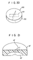
- Second valve 100 shown in Fig. 20 has cross- shaped slit 101 which passes through two end faces of disk-like soft elastic member 102, thus allowing insertion of a bar-like member having a larger diameter than that of Fig. 8.
- the first and second valves can be combined so that a slit crossing portion of the first valve overlaps a substantially central portion (in a lengthwise direction) of a slit of the second valve. Therefore, the slits of the first and second valves can overlap linearly.
- internal cross slit type disk 16' comprises a disk-shaped elastic member having a diameter of 8 mm and a height of 1.5 mm, wherein first and second arc-shaped slits 18' and 19' (length, 5.0 mm; a depth at a central point, 1.0 mm. and crossing length, 0.5 mm) are formed from two end faces of disk 16' to cross each other.
- Disk 16' was used as a first valve.
- a disk-shaped elastic member (height, 0.9 mm; diameter, 8 mm) having a Y-shaped slit whose branch slits extend linearly from the center of the member for a distance of 2.5 mm in three different directions, as shown in Fig. 8, was used as a second valve.
- These valves were mounted in a medical instrument as shown in Fig. 3 (to be referred to as sample A hereinafter).
- the first and second valves were made of silicone rubber (available from Dow-Corning Corp., trade name Q7-4735).
- sample B comparative sample
- a large number of such samples A and B were prepared.
- a pneumatic pressure of 0.3 to 0.4 kg/ cm was applied to the interior of path 14 while sealing the distal end of flexible pipe 13, and catheters having outer diameters of 3 Fr to 8 Fr were inserted 10 cm below the water surface, thus checking the presence/absence of air leakage in each sample.
- the medical instrument with valves comprises a combination of a first valve, in which a first slit open to one end face of the valve and a second slit open to the other end face thereof are formed, such that the first and second slits cross each other inside the valve, and a second valve, having a slit open to two end faces thereof. Therefore, the valves can receive and hold bar-like members having various diameters in a liquid tight state, and can be immediately recovered to an appropriate closed state when the bar-like member is removed.
- three or more valves including a first valve can be combined.
Landscapes
- Health & Medical Sciences (AREA)
- Heart & Thoracic Surgery (AREA)
- Pulmonology (AREA)
- Engineering & Computer Science (AREA)
- Anesthesiology (AREA)
- Biomedical Technology (AREA)
- Hematology (AREA)
- Life Sciences & Earth Sciences (AREA)
- Animal Behavior & Ethology (AREA)
- General Health & Medical Sciences (AREA)
- Public Health (AREA)
- Veterinary Medicine (AREA)
- Infusion, Injection, And Reservoir Apparatuses (AREA)
- Media Introduction/Drainage Providing Device (AREA)
Claims (8)
caractérisé par une deuxième vanne (17, 100) en forme de disque en parallèle avec ladite première face d'extrémité de ladite première vanne (16, 70, 80, 90) en forme de disque et venant en contact avec celle-ci et ayant une fente (21, 101) s'étendant à travers les deux faces d'extrémité de ladite vanne (17, 100) en forme de disque et étant ouverte vers celles-ci, ladite fente (21, 101) de ladite deuxième vanne (17, 100) en forme de disque étant une fente radiale, un centre de celle-ci étant conforme à l'intersection (20) des fentes (18, 19 et 71, 72, 81, 82, 91, 92) de ladite première vanne (16, 70, 80, 90) en forme de disque.
Applications Claiming Priority (2)
| Application Number | Priority Date | Filing Date | Title |
|---|---|---|---|
| JP59281077A JPS61154679A (ja) | 1984-12-28 | 1984-12-28 | 体内導入套管 |
| JP281077/84 | 1984-12-28 |
Publications (2)
| Publication Number | Publication Date |
|---|---|
| EP0198962A1 EP0198962A1 (fr) | 1986-10-29 |
| EP0198962B1 true EP0198962B1 (fr) | 1990-06-13 |
Family
ID=17633999
Family Applications (1)
| Application Number | Title | Priority Date | Filing Date |
|---|---|---|---|
| EP85116608A Expired EP0198962B1 (fr) | 1984-12-28 | 1985-12-27 | Dispositif de soupape pour un instrument médical |
Country Status (5)
| Country | Link |
|---|---|
| US (1) | US4673393A (fr) |
| EP (1) | EP0198962B1 (fr) |
| JP (1) | JPS61154679A (fr) |
| CA (1) | CA1254476A (fr) |
| DE (1) | DE3578129D1 (fr) |
Cited By (6)
| Publication number | Priority date | Publication date | Assignee | Title |
|---|---|---|---|---|
| EP0499401A1 (fr) * | 1991-02-14 | 1992-08-19 | Smiths Industries Plc | Port de prélèvement d'échantillons refermable |
| US5180376A (en) * | 1990-05-01 | 1993-01-19 | Cathco, Inc. | Non-buckling thin-walled sheath for the percutaneous insertion of intraluminal catheters |
| EP0568383A1 (fr) * | 1992-05-01 | 1993-11-03 | Ethicon, Inc. | Dispositif d'étanchéité pour trocart chirurgical |
| WO1998044983A1 (fr) | 1997-04-10 | 1998-10-15 | Createchnic Ag | Instrument d'introduction de catheter |
| DE10100756A1 (de) * | 2001-01-10 | 2002-08-14 | Universitaetsklinikum Freiburg | Vorrichtung zur Durchführung einer perkutanen Intervention in den Bereich einer menschlichen oder tierischen Lunge |
| EP3932466B1 (fr) * | 2014-04-23 | 2024-10-09 | Becton, Dickinson and Company | Cathéter à ports ou raccord luer femelle ayant une cloison antimicrobienne |
Families Citing this family (290)
| Publication number | Priority date | Publication date | Assignee | Title |
|---|---|---|---|---|
| US5308336A (en) * | 1982-09-28 | 1994-05-03 | Applied Medical Resources | Seal protection mechanism |
| US5215522A (en) * | 1984-07-23 | 1993-06-01 | Ballard Medical Products | Single use medical aspirating device and method |
| US5277177A (en) | 1984-07-23 | 1994-01-11 | Ballard Medical Products | Single use medical aspirating device and method |
| US5133345A (en) * | 1987-03-11 | 1992-07-28 | Ballard Medical Products | Neonatal closed system for involuntary aspiration and ventilation, and method |
| US5107829A (en) * | 1987-03-11 | 1992-04-28 | Ballard Medical Products | Neonatal closed system for involuntary aspiration and ventilation, and method |
| US4838255A (en) * | 1987-03-11 | 1989-06-13 | Ballard Medical Products | Neonatal closed system for involuntary aspiration and ventilation, and method |
| US4846784A (en) * | 1987-07-01 | 1989-07-11 | C. R. Bard, Inc. | Manually adjustable sphincteric system |
| US4895565A (en) * | 1987-09-21 | 1990-01-23 | Cordis Corporation | Medical instrument valve |
| US4798594A (en) * | 1987-09-21 | 1989-01-17 | Cordis Corporation | Medical instrument valve |
| US4816020A (en) * | 1987-09-28 | 1989-03-28 | Sherwood Medical Company | Retainer device for attaching members to flexible tubes and the like to flexible tubes and the like |
| JPH0194863A (ja) * | 1987-10-05 | 1989-04-13 | Terumo Corp | カテーテル導入具 |
| US5964785A (en) | 1988-01-25 | 1999-10-12 | Baxter International Inc. | Bayonet look cannula for pre-slit y-site |
| DE68927896T2 (de) | 1988-01-25 | 1997-10-23 | Baxter Int | Vorgeschlitzte Injektionsstelle und Spritz zulaufende Kanüle |
| US4960412A (en) * | 1988-04-15 | 1990-10-02 | Universal Medical Instrument Corp. | Catheter introducing system |
| US5009391A (en) * | 1988-05-02 | 1991-04-23 | The Kendall Company | Valve assembly |
| US5098393A (en) * | 1988-05-31 | 1992-03-24 | Kurt Amplatz | Medical introducer and valve assembly |
| CA1330412C (fr) | 1988-07-08 | 1994-06-28 | Steven C. Jepson | Section veineuse et canule effilee |
| US4904246A (en) * | 1988-07-19 | 1990-02-27 | Snyder Laboratories, Inc. | Cannula assembly |
| US5000745A (en) * | 1988-11-18 | 1991-03-19 | Edward Weck Incorporated | Hemostatis valve |
| IE72466B1 (en) | 1989-03-17 | 1997-04-09 | Baxter Int | Blunt-ended cannula device |
| EP0399769A1 (fr) * | 1989-05-25 | 1990-11-28 | Cook Incorporated | Canule d'hémostasie |
| US5104383A (en) * | 1989-10-17 | 1992-04-14 | United States Surgical Corporation | Trocar adapter seal and method of use |
| US5092846A (en) * | 1989-11-07 | 1992-03-03 | Sumitomo Bakelite Company Limited | Introducer for medical tube |
| US5041095A (en) * | 1989-12-22 | 1991-08-20 | Cordis Corporation | Hemostasis valve |
| US5176652A (en) * | 1989-12-22 | 1993-01-05 | Cordis Corporation | Hemostasis valve |
| US5207656A (en) * | 1990-04-19 | 1993-05-04 | Cordis Corporation | Medical instrument valve having foam partition member |
| US5065754A (en) * | 1990-06-06 | 1991-11-19 | Ballard Medical Products | Aspirating catheter tube inserter |
| US5220916A (en) * | 1990-06-14 | 1993-06-22 | Russo Ronald D | Tracheal suction catheter |
| US5395342A (en) * | 1990-07-26 | 1995-03-07 | Yoon; Inbae | Endoscopic portal |
| JPH04170966A (ja) * | 1990-11-01 | 1992-06-18 | Nippon Sherwood Kk | カテーテルイントロジューサ止血弁の弁膜体 |
| US5176651A (en) * | 1991-04-01 | 1993-01-05 | Dexide, Inc. | Combination surgical trocar housing and selective reducer sleeve assembly |
| US5180373A (en) * | 1991-06-07 | 1993-01-19 | United States Surgical Corporation | Valve system for introducing objects into anatomical body portions |
| US5154701A (en) * | 1991-06-26 | 1992-10-13 | Adam Spence Corporation | Hemostasis valve |
| US5102395A (en) * | 1991-06-26 | 1992-04-07 | Adam Spence Corporation | Hemostasis valve |
| US5385553A (en) * | 1991-07-18 | 1995-01-31 | Applied Medical Resources Corporation | Trocar with floating septum seal |
| US5269763A (en) * | 1991-07-18 | 1993-12-14 | Vernay Laboratories, Inc. | Self-sealing cannula cap |
| US5776125A (en) | 1991-07-30 | 1998-07-07 | Baxter International Inc. | Needleless vial access device |
| US5273546A (en) * | 1991-08-01 | 1993-12-28 | Medtronic, Inc. | Hemostasis valve |
| US5125903A (en) * | 1991-08-01 | 1992-06-30 | Medtronic, Inc. | Hemostasis valve |
| EP0692266B1 (fr) * | 1991-08-21 | 2000-03-22 | Smith & Nephew, Inc. | Système de contrôle de fluides |
| US5141498A (en) * | 1991-09-10 | 1992-08-25 | Unisurge, Incorporated | Flexible valve and device incorporating the same |
| US5201725A (en) * | 1991-09-26 | 1993-04-13 | Ivac | Needle free i.v. adapter |
| US6981966B2 (en) * | 1991-10-18 | 2006-01-03 | United States Surgical | Valve assembly for introducing instruments into body cavities |
| US7549424B2 (en) | 1991-10-18 | 2009-06-23 | Pro Surg, Inc. | Method and apparatus for tissue treatment with laser and electromagnetic radiation |
| US5861002A (en) * | 1991-10-18 | 1999-01-19 | Desai; Ashvin H. | Endoscopic surgical instrument |
| US6730081B1 (en) | 1991-10-18 | 2004-05-04 | Ashvin H. Desai | Endoscopic surgical instrument |
| US6569120B1 (en) | 1991-10-18 | 2003-05-27 | United States Surgical Corporation | Seal assembly |
| US5322503A (en) * | 1991-10-18 | 1994-06-21 | Desai Ashvin H | Endoscopic surgical instrument |
| US20040002647A1 (en) * | 1991-10-18 | 2004-01-01 | Ashvin Desai | Gel injection treatment of body parts |
| US6231591B1 (en) | 1991-10-18 | 2001-05-15 | 2000 Injectx, Inc. | Method of localized fluid therapy |
| US5545142A (en) * | 1991-10-18 | 1996-08-13 | Ethicon, Inc. | Seal members for surgical trocars |
| US5976129A (en) * | 1991-10-18 | 1999-11-02 | Desai; Ashvin H. | Endoscopic surgical instrument |
| US5490836A (en) * | 1991-10-18 | 1996-02-13 | Desai; Ashvin H. | Endoscopic surgical instrument |
| US5167636A (en) * | 1991-10-24 | 1992-12-01 | Mectra Labs, Inc. | Cannula sealing mechanism |
| US5336192A (en) * | 1991-11-27 | 1994-08-09 | Palestrant Aubrey M | Self-sealing valve device for angiographic catheters |
| US5197463A (en) * | 1991-12-10 | 1993-03-30 | Jeshuran Winston R | Single stage seal adaptor for endotracheal intubation and removal of anesthesia mask |
| US5334164A (en) * | 1992-01-03 | 1994-08-02 | United States Surgical Corporation | Variable interior dimension cannula assembly |
| US20050096605A1 (en) * | 1992-04-24 | 2005-05-05 | Green David T. | Valve assembly for introducing instruments into body cavities |
| CA2093748C (fr) * | 1992-04-24 | 1996-11-12 | Roy D. Gravener | Ensemble de valves permettant d'introduire des instruments dans les cavites du corps |
| US5496280A (en) * | 1992-07-02 | 1996-03-05 | Applied Medical Resources Corporation | Trocar valve assembly |
| US5443452A (en) * | 1992-07-02 | 1995-08-22 | Applied Medical Resources | Seal assembly for access device |
| US5300033A (en) * | 1992-07-09 | 1994-04-05 | Unisurge, Inc. | Introducer assembly and valve construction for use therein |
| US5300034A (en) * | 1992-07-29 | 1994-04-05 | Minnesota Mining And Manufacturing Company | Iv injection site for the reception of a blunt cannula |
| US5351383A (en) * | 1992-07-29 | 1994-10-04 | Minnesota Mining And Manufacturing Company | Method of making an injection or sampling site |
| US5368574A (en) * | 1992-10-01 | 1994-11-29 | Ethicon, Inc. | Percutaneous catheter introducer |
| US5407433A (en) * | 1993-02-10 | 1995-04-18 | Origin Medsystems, Inc. | Gas-tight seal accommodating surgical instruments with a wide range of diameters |
| US5411483A (en) * | 1993-02-10 | 1995-05-02 | Origin Medsystems, Inc. | Gas-tight seal accommodating surgical instruments with a wide range of diameters |
| US5364372A (en) * | 1993-03-29 | 1994-11-15 | Endoscopic Concepts, Inc. | Trocar and cannula |
| US5389081A (en) * | 1993-05-18 | 1995-02-14 | United States Surgical Corporation | Stabilizer for a valve assembly for introducing instruments into body cavities |
| US5322516A (en) * | 1993-05-20 | 1994-06-21 | Cobe Laboratories, Inc. | Safety needle system and method for using the same |
| US5492304A (en) * | 1993-06-16 | 1996-02-20 | United States Surgical Corporation | Seal assembly for accommodating introduction of surgical instruments |
| US5657963A (en) * | 1993-06-16 | 1997-08-19 | United States Surgical Corporation | Seal assembly for accommodating introduction of surgical instruments |
| CA2126150C (fr) * | 1993-07-14 | 2005-02-22 | David T. Green | Montage obturateur facilitant l'introduction d'instruments chirurgicaux |
| US5391154A (en) * | 1993-08-30 | 1995-02-21 | United States Surgical Corporation | Trocar seal system |
| US5569206A (en) * | 1993-09-14 | 1996-10-29 | United States Surgical Corporation | Trocar adapter seal |
| US5330437A (en) * | 1993-11-12 | 1994-07-19 | Ethicon Endo-Surgery | Self sealing flexible elastomeric valve and trocar assembly for incorporating same |
| US5718691A (en) * | 1994-02-28 | 1998-02-17 | Russo; Ronald D. | Gastrostomy feeding port with a positively sealing one-way entrance valve |
| US5545150A (en) * | 1994-05-06 | 1996-08-13 | Endoscopic Concepts, Inc. | Trocar |
| US5694922A (en) | 1994-05-18 | 1997-12-09 | Ballard Medical Products | Swivel tube connections with hermetic seals |
| US5470319A (en) | 1994-06-20 | 1995-11-28 | Critical Device Corporation | Needleless injection site |
| US5603702A (en) * | 1994-08-08 | 1997-02-18 | United States Surgical Corporation | Valve system for cannula assembly |
| US6494203B1 (en) | 1994-08-19 | 2002-12-17 | Ballard Medical Products | Medical aspirating/ventilating closed system improvements and methods |
| US5536261A (en) * | 1994-09-01 | 1996-07-16 | Stevens; Robert C. | Method and closed tip effect catheter apparatus for use in angiography |
| US5752938A (en) * | 1994-09-12 | 1998-05-19 | Richard-Allan Medical Industries, Inc. | Seal for surgical instruments |
| US5599305A (en) * | 1994-10-24 | 1997-02-04 | Cardiovascular Concepts, Inc. | Large-diameter introducer sheath having hemostasis valve and removable steering mechanism |
| US5554123A (en) * | 1994-10-31 | 1996-09-10 | Glenn Herskowitz | Portable infusion pump |
| US5643227A (en) * | 1995-01-19 | 1997-07-01 | Stevens; Robert C. | Hemostasis cannula valve apparatus and method of using same |
| US5788676A (en) * | 1996-03-25 | 1998-08-04 | Yoon; Inbae | Endoscopic portal having multiple universal seals and method of introducing instruments therethrough |
| US20030073908A1 (en) * | 1996-04-26 | 2003-04-17 | 2000 Injectx, Inc. | Method and apparatus for delivery of genes, enzymes and biological agents to tissue cells |
| US5820606A (en) * | 1996-06-11 | 1998-10-13 | Origin Medsystems, Inc. | Reusable cannula with disposable seal |
| US5792042A (en) * | 1996-08-08 | 1998-08-11 | Cohen; Kenneth L. | Apparatus for treating incontinence in females |
| US5795288A (en) * | 1996-08-08 | 1998-08-18 | Cohen; Kenneth L. | Apparatus with valve for treating incontinence |
| US8353908B2 (en) | 1996-09-20 | 2013-01-15 | Novasys Medical, Inc. | Treatment of tissue in sphincters, sinuses, and orifices |
| US6142981A (en) * | 1997-01-07 | 2000-11-07 | Daig Corporation | Hemostasis valve |
| WO1998032484A1 (fr) | 1997-01-24 | 1998-07-30 | Createchnic Ag | Instrument pour l'introduction de catheters |
| US5899234A (en) * | 1997-03-13 | 1999-05-04 | Plastic Prodution A Llc | Test closure plug for the trap bushing of a conventional T-fitting |
| US5906595A (en) * | 1997-04-25 | 1999-05-25 | Ethicon Endo-Surgery, Inc. | Trocar having protector with flexible end and improved seal assembly |
| CA2289101C (fr) | 1997-05-02 | 2006-07-18 | David C. Racenet | Systeme de joint pour trocart |
| EP0923391B1 (fr) | 1997-05-20 | 2006-08-09 | Baxter International Inc. | Connecteur sans aiguille |
| US5957898A (en) | 1997-05-20 | 1999-09-28 | Baxter International Inc. | Needleless connector |
| US5779697A (en) * | 1997-05-28 | 1998-07-14 | Linvatec Corporation | Arthroscopic cannula with fluid seals |
| DE69825763T2 (de) * | 1997-05-28 | 2005-08-25 | United States Surgical Corp., Norwalk | Versiegelungssystem für Trokar |
| US9023031B2 (en) | 1997-08-13 | 2015-05-05 | Verathon Inc. | Noninvasive devices, methods, and systems for modifying tissues |
| US6162206A (en) * | 1997-12-23 | 2000-12-19 | Baxter International Inc. | Resealable access site |
| US5989224A (en) * | 1998-02-23 | 1999-11-23 | Dexide Corporation | Universal seal for use with endoscopic cannula |
| US6419643B1 (en) | 1998-04-21 | 2002-07-16 | Alsius Corporation | Central venous catheter with heat exchange properties |
| JP3824803B2 (ja) * | 1998-05-15 | 2006-09-20 | 未来工業株式会社 | 貫通筒体及びその使用方法並びに貫通構造 |
| US20050255039A1 (en) * | 1998-06-26 | 2005-11-17 | Pro Surg, Inc., A California Corporation | Gel injection treatment of breast, fibroids & endometrial ablation |
| US6267750B1 (en) * | 1998-07-15 | 2001-07-31 | Dsu Medical Corporation | Set with angled needle |
| USD426635S (en) * | 1998-08-18 | 2000-06-13 | Genicon, Lc | Combination trocar, cannula, and valve |
| US6402748B1 (en) * | 1998-09-23 | 2002-06-11 | Sherwood Services Ag | Electrosurgical device having a dielectrical seal |
| US6086570A (en) * | 1998-09-29 | 2000-07-11 | A-Med Systems, Inc. | Hemostasis valve with membranes having offset apertures |
| US7998068B2 (en) | 1998-12-01 | 2011-08-16 | Atropos Limited | Instrument access device |
| CA2351643C (fr) | 1998-12-01 | 2010-02-02 | Atropos Limited | Dispositif chirurgical utilise pour effectuer la retraction et/ou la fermeture d'une incision |
| US7537564B2 (en) | 1998-12-01 | 2009-05-26 | Atropos Limited | Wound retractor device |
| US7559893B2 (en) | 1998-12-01 | 2009-07-14 | Atropos Limited | Wound retractor device |
| US6254061B1 (en) * | 1999-04-30 | 2001-07-03 | Scimed Life Systems, Inc. | Medical suction valve |
| JP4683169B2 (ja) * | 1999-06-18 | 2011-05-11 | 有限会社ウサミナノテクノロジー | カテーテルイントロデューサ |
| US7540839B2 (en) | 1999-10-14 | 2009-06-02 | Atropos Limited | Wound retractor |
| CN1331441C (zh) | 1999-10-14 | 2007-08-15 | 阿特波斯有限公司 | 创口牵引器 |
| US8021296B2 (en) | 1999-12-01 | 2011-09-20 | Atropos Limited | Wound retractor |
| US6632200B2 (en) | 2000-01-25 | 2003-10-14 | St. Jude Medical, Daig Division | Hemostasis valve |
| US6551283B1 (en) | 2000-01-25 | 2003-04-22 | St. Jude Medical, Daig Division | Hemostasis valve |
| USD449887S1 (en) | 2000-01-26 | 2001-10-30 | Genicon Lc | Combined obturator, cannula and valve assembly |
| US7153319B1 (en) | 2000-01-26 | 2006-12-26 | Genico, Inc. | Trocar system having shielded trocar |
| US6595946B1 (en) * | 2000-02-25 | 2003-07-22 | United States Surgical Corporation | Valve assembly |
| USD443360S1 (en) | 2000-03-22 | 2001-06-05 | Dexterity Surgical Inc. | Distal end of obturator for a trocar |
| AU2001246399A1 (en) * | 2000-04-06 | 2001-10-23 | Maersk Medical A/S | A coupling arrangement |
| AU2001233625A1 (en) | 2000-04-06 | 2001-10-23 | Maersk Medical A/S | A manifold |
| DK174620B1 (da) * | 2000-04-06 | 2003-07-28 | Maersk Medical As | En ventilanordning |
| JP4050445B2 (ja) * | 2000-06-23 | 2008-02-20 | テルモ株式会社 | 継管具、接続口作製具および継管システム |
| IT1318743B1 (it) * | 2000-08-08 | 2003-09-10 | Dideco Spa | Unita' pompante pulsatile per fluido, particolarmente sangue. |
| DE20015388U1 (de) * | 2000-09-06 | 2001-03-15 | Storm, Gerald, Dr., 86159 Augsburg | Vorrichtung zur Abdichtung und Schmierung von in Trokarhülsen geführten Instrumenten |
| US6470219B1 (en) * | 2000-10-02 | 2002-10-22 | Novasys Medical, Inc. | Apparatus and method for treating female urinary incontinence |
| US7306591B2 (en) | 2000-10-02 | 2007-12-11 | Novasys Medical, Inc. | Apparatus and methods for treating female urinary incontinence |
| DE60142978D1 (de) | 2000-10-19 | 2010-10-14 | Applied Med Resources | Chirurgisches zugangsgerät und -verfahren |
| US6942671B1 (en) | 2000-11-06 | 2005-09-13 | Tyco Healthcare Group Lp | Surgical sealing apparatus |
| JP4048431B2 (ja) * | 2000-12-04 | 2008-02-20 | 株式会社ジェイ・エム・エス | 薬液容器用栓体 |
| WO2002058606A1 (fr) * | 2001-01-24 | 2002-08-01 | Alsius Corporation | Catheter veineux central presentant des proprietes d'echange de chaleur |
| ITPD20010017A1 (it) * | 2001-01-26 | 2002-07-26 | Bidoia Sas Di Gianfranco Bidoi | Attrezzatura perfezionata particolarmente per il collocamento operativo di strumenti in cavita' a pressione controllata nel campo chirurgico |
| JP3640616B2 (ja) * | 2001-04-02 | 2005-04-20 | サンアイ株式会社 | 乾燥剤用ディスペンサのカバー |
| US6610031B1 (en) | 2001-04-18 | 2003-08-26 | Origin Medsystems, Inc. | Valve assembly |
| US7037303B2 (en) | 2001-07-06 | 2006-05-02 | Opticon Medical, Inc. | Urinary flow control valve |
| WO2003015848A1 (fr) | 2001-08-14 | 2003-02-27 | Applied Medical Resources Corporation | Procede et appareil de fermeture hermetique d'un acces |
| US6958037B2 (en) | 2001-10-20 | 2005-10-25 | Applied Medical Resources Corporation | Wound retraction apparatus and method |
| US6908459B2 (en) | 2001-12-07 | 2005-06-21 | Becton, Dickinson And Company | Needleless luer access connector |
| US20060220325A1 (en) * | 2002-04-26 | 2006-10-05 | Mcfarlane Richard H | Floating seal assembly for a trocar |
| EP2263718A1 (fr) * | 2002-04-26 | 2010-12-22 | Teleflex Medical Incorporated | Ensemble formant joint flottant pour trocart |
| US7632250B2 (en) * | 2002-05-10 | 2009-12-15 | Tyco Healthcare Group Lp | Introducer seal assembly |
| US7160272B1 (en) | 2002-05-31 | 2007-01-09 | Elcam Plastic | Y-site medical valve |
| EP2343032B1 (fr) | 2002-06-05 | 2012-05-09 | Applied Medical Resources Corporation | Écarteur de plaies |
| AU2003254107B2 (en) | 2002-07-25 | 2008-06-19 | Covidien Ag | Electrosurgical pencil with drag sensing capability |
| US9271753B2 (en) | 2002-08-08 | 2016-03-01 | Atropos Limited | Surgical device |
| ES2287516T3 (es) | 2002-09-19 | 2007-12-16 | Atropos Limited | Sistema retractor de herida. |
| US7025744B2 (en) * | 2002-10-04 | 2006-04-11 | Dsu Medical Corporation | Injection site for male luer or other tubular connector |
| US8377039B2 (en) | 2002-10-04 | 2013-02-19 | Nxstage Medical, Inc. | Injection site for male luer or other tubular connector |
| US20050020884A1 (en) | 2003-02-25 | 2005-01-27 | Hart Charles C. | Surgical access system |
| US7988679B2 (en) | 2003-03-18 | 2011-08-02 | Navilyst Medical, Inc. | Pressure responsive slit valve assembly for a plurality of fluids and uses thereof |
| US7435236B2 (en) | 2003-06-27 | 2008-10-14 | Navilyst Medical, Inc. | Pressure actuated valve with improved biasing member |
| US20050020975A1 (en) * | 2003-07-23 | 2005-01-27 | Dr. Iftikhar Khan | [Khan Orotracheal Suction System] |
| AU2004263142A1 (en) | 2003-08-06 | 2005-02-17 | Applied Medical Resources Corporation | Surgical device with tack-free gel and method of manufacture |
| US7252652B2 (en) * | 2003-08-29 | 2007-08-07 | Boston Scientific Scimed, Inc. | Valved catheters including high flow rate catheters |
| US7163510B2 (en) | 2003-09-17 | 2007-01-16 | Applied Medical Resources Corporation | Surgical instrument access device |
| US7988664B2 (en) | 2004-11-01 | 2011-08-02 | Tyco Healthcare Group Lp | Locking clip with trigger bushing |
| US7226434B2 (en) | 2003-10-31 | 2007-06-05 | Tyco Healthcare Group Lp | Safety shield |
| US20050165364A1 (en) * | 2004-01-22 | 2005-07-28 | Dimatteo Kristian | Valved catheter to bypass connector |
| US8187234B2 (en) * | 2004-01-29 | 2012-05-29 | Navilyst Medical, Inc. | Pressure activated safety valve with anti-adherent coating |
| US9933079B2 (en) | 2004-01-29 | 2018-04-03 | Angiodynamics, Inc. | Stacked membrane for pressure actuated valve |
| US9314608B2 (en) | 2004-01-29 | 2016-04-19 | Angiodynamics, Inc | Pressure activated safety valve with high flow slit |
| US8034035B2 (en) | 2004-01-29 | 2011-10-11 | Navilyst Medical, Inc. | Pressure activated safety valve with high flow slit |
| US7854731B2 (en) | 2004-03-18 | 2010-12-21 | C. R. Bard, Inc. | Valved catheter |
| US7578803B2 (en) | 2004-03-18 | 2009-08-25 | C. R. Bard, Inc. | Multifunction adaptor for an open-ended catheter |
| US8083728B2 (en) | 2004-03-18 | 2011-12-27 | C. R. Bard, Inc. | Multifunction adaptor for an open-ended catheter |
| US7094218B2 (en) | 2004-03-18 | 2006-08-22 | C. R. Bard, Inc. | Valved catheter |
| US7594911B2 (en) | 2004-03-18 | 2009-09-29 | C. R. Bard, Inc. | Connector system for a proximally trimmable catheter |
| US7594910B2 (en) | 2004-03-18 | 2009-09-29 | C. R. Bard, Inc. | Catheter connector |
| US7377915B2 (en) | 2004-04-01 | 2008-05-27 | C. R. Bard, Inc. | Catheter connector system |
| JP2008504051A (ja) * | 2004-04-05 | 2008-02-14 | タイコ ヘルスケア グループ リミテッド パートナーシップ | 外科手術用ハンドアクセス装置 |
| WO2005107843A1 (fr) | 2004-04-30 | 2005-11-17 | C.R. Bard, Inc. | Intubateur a gaine a valve pour canule veineuse |
| US7063685B2 (en) * | 2004-05-12 | 2006-06-20 | C. R. Bard, Inc. | Hemostasis valve for a catheter |
| US7347853B2 (en) * | 2004-05-12 | 2008-03-25 | C. R. Bard, Inc. | Catheter with removable extension |
| US8177760B2 (en) * | 2004-05-12 | 2012-05-15 | C. R. Bard, Inc. | Valved connector |
| US7469458B1 (en) | 2004-08-11 | 2008-12-30 | Proteckt Catheters, Llc | Method of assembling a catheter with integrated pre-slit cannula diaphragm |
| US20060071432A1 (en) * | 2004-09-29 | 2006-04-06 | Staudner Rupert A | Seal for trocar |
| US8403890B2 (en) * | 2004-11-29 | 2013-03-26 | C. R. Bard, Inc. | Reduced friction catheter introducer and method of manufacturing and using the same |
| US8932260B2 (en) * | 2004-11-29 | 2015-01-13 | C. R. Bard, Inc. | Reduced-friction catheter introducer and method of manufacturing and using the same |
| US8926564B2 (en) | 2004-11-29 | 2015-01-06 | C. R. Bard, Inc. | Catheter introducer including a valve and valve actuator |
| US9597483B2 (en) | 2004-11-29 | 2017-03-21 | C. R. Bard, Inc. | Reduced-friction catheter introducer and method of manufacturing and using the same |
| US7347458B2 (en) * | 2005-01-14 | 2008-03-25 | C. R. Bard, Inc. | Locking luer fitting |
| US8328768B2 (en) * | 2005-02-11 | 2012-12-11 | Angiodynamics, Inc | Pressure activated safety valve with improved flow characteristics and durability |
| US7931624B2 (en) * | 2005-04-05 | 2011-04-26 | Tyco Healthcare Group Lp | Introducer seal assembly with low profile gimbal seal |
| US20060264966A1 (en) * | 2005-05-12 | 2006-11-23 | Med Institute, Inc. | Vertebroplasty leak prevention sleeve and method |
| US7875019B2 (en) | 2005-06-20 | 2011-01-25 | C. R. Bard, Inc. | Connection system for multi-lumen catheter |
| US7500974B2 (en) | 2005-06-28 | 2009-03-10 | Covidien Ag | Electrode with rotatably deployable sheath |
| US20090125018A1 (en) * | 2005-08-26 | 2009-05-14 | Ams Research Corporation | Heat Treatment System For Pelvic Support Tissue |
| EP2272447B1 (fr) | 2005-10-14 | 2012-01-18 | Applied Medical Resources Corporation | Rétracteur de plaies pourvu d'un anneau fendu |
| US20070106228A1 (en) * | 2005-11-09 | 2007-05-10 | David Bell | Flexible valve for blood treatment set |
| TWM293772U (en) * | 2005-11-10 | 2006-07-11 | Wu Pei Jen | Safety injection catheter |
| ES2381137T3 (es) | 2005-12-02 | 2012-05-23 | C.R.Bard, Inc. | Válvulas proximales activadas por presión |
| US8585660B2 (en) | 2006-01-25 | 2013-11-19 | Navilyst Medical, Inc. | Valved catheter with power injection bypass |
| CN101421000B (zh) * | 2006-03-20 | 2013-01-30 | 麦德托尼克公司 | 可断裂的或可去除的阀和器械 |
| WO2008011225A2 (fr) * | 2006-07-19 | 2008-01-24 | Richard Spaide | Système d'instruments pour chirurgie de vitrectomie comprenant un trochart tranchant, une canule et un capuchon à valve pour la canule, et son procédé d'utilisation |
| US20080027410A1 (en) * | 2006-07-28 | 2008-01-31 | Becton, Dickinson And Company | Vascular access device non-adhering membranes |
| JP5235017B2 (ja) * | 2006-08-25 | 2013-07-10 | テレフレックス メディカル インコーポレイテッド | 枠付浮動シール装置 |
| US8840625B2 (en) * | 2006-10-18 | 2014-09-23 | Hologic, Inc. | Systems for performing gynecological procedures with closed visualization lumen |
| US9392935B2 (en) | 2006-11-07 | 2016-07-19 | Hologic, Inc. | Methods for performing a medical procedure |
| US8025656B2 (en) | 2006-11-07 | 2011-09-27 | Hologic, Inc. | Methods, systems and devices for performing gynecological procedures |
| US8105315B2 (en) * | 2006-11-08 | 2012-01-31 | Cardiac Pacemakers, Inc. | Break-away hemostasis hub |
| US8360969B2 (en) * | 2007-03-29 | 2013-01-29 | Frantz Medical Development, Ltd. | Securable cannula and method |
| US9259233B2 (en) | 2007-04-06 | 2016-02-16 | Hologic, Inc. | Method and device for distending a gynecological cavity |
| US20090270898A1 (en) | 2007-04-06 | 2009-10-29 | Interlace Medical, Inc. | Tissue removal device with high reciprocation rate |
| EP2134283B1 (fr) | 2007-04-06 | 2014-06-11 | Hologic, Inc. | Système et dispositif d'exérèse de tissu |
| US9095366B2 (en) | 2007-04-06 | 2015-08-04 | Hologic, Inc. | Tissue cutter with differential hardness |
| US8387810B2 (en) | 2007-04-16 | 2013-03-05 | Becton, Dickinson And Company | Pierceable cap having piercing extensions for a sample container |
| US8387811B2 (en) * | 2007-04-16 | 2013-03-05 | Bd Diagnostics | Pierceable cap having piercing extensions |
| US8226552B2 (en) | 2007-05-11 | 2012-07-24 | Applied Medical Resources Corporation | Surgical retractor |
| CA2682923C (fr) | 2007-05-11 | 2014-10-07 | Applied Medical Resources Corporation | Ecarteur chirurgical avec coussin de gel |
| EP2152175B1 (fr) | 2007-06-05 | 2015-10-28 | Atropos Limited | Dispositif d'accès à un instrument |
| US8657740B2 (en) | 2007-06-05 | 2014-02-25 | Atropos Limited | Instrument access device |
| US20090069837A1 (en) * | 2007-08-20 | 2009-03-12 | Atropos Limited | Hand and instrument access device |
| WO2009042874A1 (fr) * | 2007-09-27 | 2009-04-02 | Tyco Healthcare Group Lp | Ensemble cathéter i.v. et dispositif de sécurité pour aiguille |
| WO2009052327A1 (fr) * | 2007-10-19 | 2009-04-23 | C.R. Bard, Inc. | Introducteur comprenant une région distale mise en forme |
| US8118784B2 (en) * | 2007-10-30 | 2012-02-21 | Cook Medical Technologies Llc | Haemostatic valve |
| EP2205307B1 (fr) * | 2007-10-30 | 2011-03-16 | William Cook Europe ApS | Valve hémostatique |
| ATE482738T1 (de) | 2007-12-20 | 2010-10-15 | Tyco Healthcare | Verschlusskappeanordnung mit gefederter manschette |
| WO2009094476A1 (fr) | 2008-01-22 | 2009-07-30 | Applied Medical Resources Corporation | Dispositif d'accès d'instrument chirurgical |
| GB2457233B (en) * | 2008-02-05 | 2012-02-08 | Lagis Entpr Co Ltd | Air-leakage prevention structure for a catheter needle |
| US20090259185A1 (en) * | 2008-04-15 | 2009-10-15 | Tyco Healthcare Group Lp | Self-conforming surgical seal |
| US8257321B2 (en) * | 2008-05-21 | 2012-09-04 | Navilyst Medical, Inc. | Pressure activated valve for high flow rate and pressure venous access applications |
| US9788773B2 (en) | 2008-05-21 | 2017-10-17 | Robert J. Perry | Vein presentation enhancement device |
| ES2975367T3 (es) | 2008-10-13 | 2024-07-04 | Applied Med Resources | Sistema de acceso de vía única |
| US8882714B1 (en) | 2009-01-23 | 2014-11-11 | Robert J. Perry | Needle with gated stylet |
| US8337470B2 (en) * | 2009-01-28 | 2012-12-25 | Angiodynamics, Inc. | Three-way valve for power injection in vascular access devices |
| US8083721B2 (en) | 2009-01-29 | 2011-12-27 | Navilyst Medical, Inc. | Power injection valve |
| US8375955B2 (en) | 2009-02-06 | 2013-02-19 | Atropos Limited | Surgical procedure |
| US7850653B2 (en) * | 2009-03-23 | 2010-12-14 | Tyco Healthcare Group Lp | Access port including rotatable seals |
| US8206357B2 (en) * | 2009-03-26 | 2012-06-26 | Tyco Healthcare Group Lp | Articulating surgical portal apparatus with spring |
| US11903602B2 (en) | 2009-04-29 | 2024-02-20 | Hologic, Inc. | Uterine fibroid tissue removal device |
| WO2010151825A1 (fr) * | 2009-06-26 | 2010-12-29 | C. R. Bard, Inc. | Cathéter à ajustement proximal comprenant une bifurcation préfixée et ses procédés |
| US8317754B2 (en) | 2009-07-06 | 2012-11-27 | AUST Development, LLC | Valves and hubs for tubular devices and methods for making and using them |
| US8007468B2 (en) | 2009-07-13 | 2011-08-30 | Navilyst Medical, Inc. | Method to secure an elastic component in a valve |
| US8512293B2 (en) | 2009-08-13 | 2013-08-20 | AUST Development, LLC | Valves and hubs for tubular medical devices and methods for making and using them |
| IE20100592A1 (en) | 2009-09-17 | 2011-05-11 | Atropos Ltd | An instrument access device |
| MY163971A (en) * | 2009-10-01 | 2017-11-15 | Braun Melsungen Ag | Catheter insertion device |
| US8430812B2 (en) * | 2009-10-05 | 2013-04-30 | Covidien Lp | Surgical access assembly |
| US20110087093A1 (en) * | 2009-10-09 | 2011-04-14 | Navilyst Medical, Inc. | Valve configurations for implantable medical devices |
| US20110112375A1 (en) * | 2009-11-12 | 2011-05-12 | Tyco Healthcare Group Lp | Portal apparatus including conformable cup seal |
| EP2498668A4 (fr) | 2009-11-13 | 2013-08-07 | Hologic Inc | Système d'accès avec un canal d'évacuation amovible |
| US20110118612A1 (en) * | 2009-11-18 | 2011-05-19 | Navilyst Medical, Inc. | Valved Catheter with Integrated Pressure Measurement Capabilities |
| JP5479880B2 (ja) * | 2009-12-22 | 2014-04-23 | 株式会社パイオラックスメディカルデバイス | 医療用シース |
| GB2480272B (en) | 2010-05-11 | 2012-10-10 | Cook Medical Technologies Llc | Haemostatic valve assembly |
| US8137321B2 (en) * | 2010-05-12 | 2012-03-20 | Medtronic Vascular, Inc. | Introducer sheath |
| US9192752B2 (en) | 2010-07-05 | 2015-11-24 | AUST Development, LLC | Serial valves and hubs for tubular devices and methods for making and using them |
| US8298209B2 (en) * | 2010-07-30 | 2012-10-30 | Medtronic, Inc. | Sealing for medical devices/instruments |
| AU2011308636B2 (en) | 2010-10-01 | 2015-06-04 | Applied Medical Resources Corporation | Surgical access port system |
| US9289115B2 (en) | 2010-10-01 | 2016-03-22 | Applied Medical Resources Corporation | Natural orifice surgery system |
| GB2485172B (en) | 2010-11-03 | 2014-04-09 | Cook Medical Technologies Llc | Haemostatic valve assembly |
| US10420585B2 (en) | 2011-02-16 | 2019-09-24 | Reza Mohajer-Shojaee | Laparoscopic cannula with suturing passage cutoff |
| US9033872B2 (en) * | 2011-02-16 | 2015-05-19 | Reza Mohajer-Shojaee | Laparoscopic cannula with suturing capability |
| JP6005143B2 (ja) | 2011-05-10 | 2016-10-12 | アプライド メディカル リソーシーズ コーポレイション | 開創器 |
| US9295827B2 (en) * | 2013-04-29 | 2016-03-29 | Gale Harrison Thorne | Twisted slit valve |
| US8403927B1 (en) | 2012-04-05 | 2013-03-26 | William Bruce Shingleton | Vasectomy devices and methods |
| US9895524B2 (en) | 2012-07-13 | 2018-02-20 | Angiodynamics, Inc. | Fluid bypass device for valved catheters |
| US9114231B2 (en) | 2013-03-15 | 2015-08-25 | B. Braun Melsungen Ag | Valved catheter assemblies and related methods |
| EP3603534B1 (fr) | 2013-03-15 | 2024-07-17 | Applied Medical Resources Corporation | Dispositif d'accès chirurgical de gel mécanique |
| CN104043180B (zh) * | 2013-03-15 | 2019-07-16 | B.布劳恩梅尔松根股份公司 | 阀控导管组件和相关方法 |
| WO2014189677A1 (fr) * | 2013-05-20 | 2014-11-27 | St. Jude Medical, Cardiology Division, Inc. | Ensemble gaine à grand diamètre |
| GB2508570C2 (en) | 2013-08-21 | 2025-07-30 | Braun Melsungen Ag | Catheter assembly |
| SG10201500101RA (en) | 2014-01-08 | 2015-08-28 | Braun Melsungen Ag | Catheter assemblies with valves and related methods |
| EP3169510B1 (fr) | 2014-07-18 | 2018-10-03 | Applied Medical Resources Corporation | Procédé de fabrication de gels présentant des revêtements non collants permanents |
| EP3498204B1 (fr) | 2014-08-15 | 2022-10-05 | Applied Medical Resources Corporation | Système de chirurgie d'orifice naturel |
| WO2016051759A1 (fr) * | 2014-09-29 | 2016-04-07 | テルモ株式会社 | Raccord femelle, raccord mâle, et corps de liaison de raccord |
| WO2016073954A1 (fr) | 2014-11-07 | 2016-05-12 | C. R. Bard, Inc. | Système de connexion pour des cathéters en tunnel |
| US9949730B2 (en) | 2014-11-25 | 2018-04-24 | Applied Medical Resources Corporation | Circumferential wound retraction with support and guidance structures |
| EP3552652B2 (fr) | 2015-08-18 | 2024-07-03 | B. Braun Melsungen AG | Dispositifs de cathéters à soupapes |
| US10368908B2 (en) | 2015-09-15 | 2019-08-06 | Applied Medical Resources Corporation | Surgical robotic access system |
| CA3001311A1 (fr) | 2015-10-07 | 2017-04-13 | Applied Medical Resources Corporation | Ecarteur de plaie a bague exterieure a segments multiples |
| US10610678B2 (en) | 2016-08-11 | 2020-04-07 | Angiodynamics, Inc. | Bi-directional, pressure-actuated medical valve with improved fluid flow control and method of using such |
| ES3038451T3 (en) | 2016-09-12 | 2025-10-13 | Applied Med Resources | Surgical robotic access system for irregularly shaped robotic actuators and associated robotic surgical instruments |
| CN110446524B (zh) * | 2016-11-09 | 2021-10-26 | 波士顿科学有限公司 | 用于止血阀的低压密封件设计 |
| WO2018169685A1 (fr) | 2017-03-13 | 2018-09-20 | Boston Scientific Scimed, Inc. | Valves d'hémostase et procédés de fabrication et d'utilisation de valves d'hémostase |
| WO2018169660A1 (fr) | 2017-03-13 | 2018-09-20 | Boston Scientific Limited | Valves hémostatiques et procédés de fabrication et d'utilisation des valves hémostatiques |
| US10349929B2 (en) * | 2017-03-24 | 2019-07-16 | Medos International Sarl | Cannula with cap |
| EP3398646B1 (fr) | 2017-05-05 | 2019-10-09 | Greatbatch Ltd. | Dispositif médical avec valve hémostatique |
| US20180326170A1 (en) * | 2017-05-09 | 2018-11-15 | Brian Kamradt | Medical device system including a tracheal tube and method |
| WO2019040801A1 (fr) | 2017-08-23 | 2019-02-28 | C.R. Bard, Inc. | Ensembles cathéters et procédés associés |
| CN109431813A (zh) * | 2017-08-31 | 2019-03-08 | 美昕医疗器械(昆山)有限公司 | 用于置换胃肠造瘘管的装置 |
| WO2019055411A1 (fr) | 2017-09-12 | 2019-03-21 | Boston Scientific Limited | Valves d'hémostase et procédés de fabrication et d'utilisation de valves d'hémostase |
| WO2020127328A1 (fr) | 2018-12-17 | 2020-06-25 | B. Braun Melsungen Ag | Ensembles cathéter sur aiguille et leur procédé de fabrication |
| US11260146B2 (en) * | 2019-11-27 | 2022-03-01 | Terumo Medical Corporation | Seal-healing valve for a medical instrument |
Family Cites Families (19)
| Publication number | Priority date | Publication date | Assignee | Title |
|---|---|---|---|---|
| US3853127A (en) * | 1973-04-03 | 1974-12-10 | R Spademan | Elastic sealing member |
| US4000739A (en) * | 1975-07-09 | 1977-01-04 | Cordis Corporation | Hemostasis cannula |
| US4143853A (en) * | 1977-07-14 | 1979-03-13 | Metatech Corporation | Valve for use with a catheter or the like |
| US4177814A (en) * | 1978-01-18 | 1979-12-11 | KLI, Incorporated | Self-sealing cannula |
| US4412836A (en) * | 1979-04-27 | 1983-11-01 | The West Company, Incorporated | Syringe assembly |
| US4244379A (en) * | 1979-08-02 | 1981-01-13 | Quest Medical, Inc. | Check valve for blood drawing apparatus |
| DE3042229C2 (de) * | 1980-11-08 | 1983-10-27 | B. Braun Melsungen Ag, 3508 Melsungen | Einführungsvorrichtung zum Einbringen langgestreckter Gegenstände in Blutgefäße |
| US4430081A (en) * | 1981-01-06 | 1984-02-07 | Cook, Inc. | Hemostasis sheath |
| US4436519A (en) * | 1981-05-28 | 1984-03-13 | Argon Medical Corp. | Removable hemostasis valve |
| US4475548A (en) * | 1982-06-01 | 1984-10-09 | Rudolph Muto | Fitting for endotracheal tube apparatus and method of making the fitting |
| JPS59133877A (ja) * | 1983-01-18 | 1984-08-01 | Terumo Corp | 弁体 |
| JPS59164067A (ja) * | 1983-03-07 | 1984-09-17 | テルモ株式会社 | バル−ンカテ−テル |
| JPS59131364A (ja) * | 1983-01-18 | 1984-07-28 | テルモ株式会社 | 弁体付カテ−テル |
| JPS6088562A (ja) * | 1983-10-22 | 1985-05-18 | テルモ株式会社 | 弁体付穿刺針 |
| US4610665A (en) * | 1983-01-18 | 1986-09-09 | Terumo Kabushiki Kaisha | Medical instrument |
| JPS59155255A (ja) * | 1983-02-23 | 1984-09-04 | テルモ株式会社 | 弁体付連結具 |
| JPS59131366A (ja) * | 1983-10-22 | 1984-07-28 | テルモ株式会社 | 弁体付連結具 |
| JPS6171065A (ja) * | 1984-09-13 | 1986-04-11 | テルモ株式会社 | カテ−テルイントロデユ−サ |
| US4626245A (en) * | 1985-08-30 | 1986-12-02 | Cordis Corporation | Hemostatis valve comprising an elastomeric partition having opposed intersecting slits |
-
1984
- 1984-12-28 JP JP59281077A patent/JPS61154679A/ja active Pending
-
1985
- 1985-12-24 US US06/813,025 patent/US4673393A/en not_active Expired - Fee Related
- 1985-12-27 EP EP85116608A patent/EP0198962B1/fr not_active Expired
- 1985-12-27 DE DE8585116608T patent/DE3578129D1/de not_active Expired - Fee Related
- 1985-12-30 CA CA000498796A patent/CA1254476A/fr not_active Expired
Cited By (6)
| Publication number | Priority date | Publication date | Assignee | Title |
|---|---|---|---|---|
| US5180376A (en) * | 1990-05-01 | 1993-01-19 | Cathco, Inc. | Non-buckling thin-walled sheath for the percutaneous insertion of intraluminal catheters |
| EP0499401A1 (fr) * | 1991-02-14 | 1992-08-19 | Smiths Industries Plc | Port de prélèvement d'échantillons refermable |
| EP0568383A1 (fr) * | 1992-05-01 | 1993-11-03 | Ethicon, Inc. | Dispositif d'étanchéité pour trocart chirurgical |
| WO1998044983A1 (fr) | 1997-04-10 | 1998-10-15 | Createchnic Ag | Instrument d'introduction de catheter |
| DE10100756A1 (de) * | 2001-01-10 | 2002-08-14 | Universitaetsklinikum Freiburg | Vorrichtung zur Durchführung einer perkutanen Intervention in den Bereich einer menschlichen oder tierischen Lunge |
| EP3932466B1 (fr) * | 2014-04-23 | 2024-10-09 | Becton, Dickinson and Company | Cathéter à ports ou raccord luer femelle ayant une cloison antimicrobienne |
Also Published As
| Publication number | Publication date |
|---|---|
| US4673393A (en) | 1987-06-16 |
| DE3578129D1 (de) | 1990-07-19 |
| JPS61154679A (ja) | 1986-07-14 |
| EP0198962A1 (fr) | 1986-10-29 |
| CA1254476A (fr) | 1989-05-23 |
Similar Documents
| Publication | Publication Date | Title |
|---|---|---|
| US4673393A (en) | Medical instrument | |
| US4610665A (en) | Medical instrument | |
| US4737152A (en) | Catheter assembly | |
| US4909798A (en) | Universal hemostasis cannula | |
| US5125903A (en) | Hemostasis valve | |
| EP0416467B1 (fr) | Valve médicale et sa méthode de fabrication, cathéter avec valve et ensemble de cathéter | |
| EP0513969B1 (fr) | Valve hémostatique | |
| US4932633A (en) | Hemostasis valve | |
| US5944697A (en) | Percutaneous catheter introducer | |
| US4946133A (en) | Hemostasis valve | |
| US5273546A (en) | Hemostasis valve | |
| EP0900105B1 (fr) | Valve hemostatique | |
| JPH02949B2 (fr) | ||
| JPH027669B2 (fr) | ||
| JPH02189163A (ja) | 止血弁 | |
| JPH07163666A (ja) | コネクタ | |
| JP2006527605A (ja) | 表示器付き止血薬バルブアセンブリー | |
| JPH025431B2 (fr) | ||
| JPH0194863A (ja) | カテーテル導入具 | |
| JPH0230695B2 (fr) | ||
| CN115103697B (zh) | 外部终端装置及其到流动管线的连接方法 | |
| JPH0230696B2 (fr) | ||
| JPH0736663Y2 (ja) | 医療用チューブ導入用具 | |
| JPH0211260B2 (fr) |
Legal Events
| Date | Code | Title | Description |
|---|---|---|---|
| PUAI | Public reference made under article 153(3) epc to a published international application that has entered the european phase |
Free format text: ORIGINAL CODE: 0009012 |
|
| 17P | Request for examination filed |
Effective date: 19860124 |
|
| AK | Designated contracting states |
Kind code of ref document: A1 Designated state(s): BE DE FR GB IT SE |
|
| 17Q | First examination report despatched |
Effective date: 19880406 |
|
| GRAA | (expected) grant |
Free format text: ORIGINAL CODE: 0009210 |
|
| ITF | It: translation for a ep patent filed | ||
| AK | Designated contracting states |
Kind code of ref document: B1 Designated state(s): BE DE FR GB IT SE |
|
| REF | Corresponds to: |
Ref document number: 3578129 Country of ref document: DE Date of ref document: 19900719 |
|
| ET | Fr: translation filed | ||
| ITTA | It: last paid annual fee | ||
| PLBE | No opposition filed within time limit |
Free format text: ORIGINAL CODE: 0009261 |
|
| STAA | Information on the status of an ep patent application or granted ep patent |
Free format text: STATUS: NO OPPOSITION FILED WITHIN TIME LIMIT |
|
| 26N | No opposition filed | ||
| EAL | Se: european patent in force in sweden |
Ref document number: 85116608.2 |
|
| PGFP | Annual fee paid to national office [announced via postgrant information from national office to epo] |
Ref country code: FR Payment date: 19951212 Year of fee payment: 11 |
|
| PGFP | Annual fee paid to national office [announced via postgrant information from national office to epo] |
Ref country code: SE Payment date: 19951215 Year of fee payment: 11 |
|
| PGFP | Annual fee paid to national office [announced via postgrant information from national office to epo] |
Ref country code: GB Payment date: 19951218 Year of fee payment: 11 |
|
| PGFP | Annual fee paid to national office [announced via postgrant information from national office to epo] |
Ref country code: DE Payment date: 19951222 Year of fee payment: 11 |
|
| PGFP | Annual fee paid to national office [announced via postgrant information from national office to epo] |
Ref country code: BE Payment date: 19960212 Year of fee payment: 11 |
|
| PG25 | Lapsed in a contracting state [announced via postgrant information from national office to epo] |
Ref country code: GB Effective date: 19961227 |
|
| PG25 | Lapsed in a contracting state [announced via postgrant information from national office to epo] |
Ref country code: SE Effective date: 19961228 |
|
| PG25 | Lapsed in a contracting state [announced via postgrant information from national office to epo] |
Ref country code: BE Effective date: 19961231 |
|
| BERE | Be: lapsed |
Owner name: TERUMO K.K. TRADING AS TERUMO CORP. Effective date: 19961231 |
|
| GBPC | Gb: european patent ceased through non-payment of renewal fee |
Effective date: 19961227 |
|
| PG25 | Lapsed in a contracting state [announced via postgrant information from national office to epo] |
Ref country code: FR Effective date: 19970829 |
|
| PG25 | Lapsed in a contracting state [announced via postgrant information from national office to epo] |
Ref country code: DE Effective date: 19970902 |
|
| EUG | Se: european patent has lapsed |
Ref document number: 85116608.2 |
|
| REG | Reference to a national code |
Ref country code: FR Ref legal event code: ST |