EP0199062A2 - Dispositif pour couper des structures en nids d'abeilles - Google Patents
Dispositif pour couper des structures en nids d'abeilles Download PDFInfo
- Publication number
- EP0199062A2 EP0199062A2 EP19860103395 EP86103395A EP0199062A2 EP 0199062 A2 EP0199062 A2 EP 0199062A2 EP 19860103395 EP19860103395 EP 19860103395 EP 86103395 A EP86103395 A EP 86103395A EP 0199062 A2 EP0199062 A2 EP 0199062A2
- Authority
- EP
- European Patent Office
- Prior art keywords
- cutting
- cutting knife
- teeth
- tooth
- deflector
- Prior art date
- Legal status (The legal status is an assumption and is not a legal conclusion. Google has not performed a legal analysis and makes no representation as to the accuracy of the status listed.)
- Granted
Links
Images
Classifications
-
- B—PERFORMING OPERATIONS; TRANSPORTING
- B27—WORKING OR PRESERVING WOOD OR SIMILAR MATERIAL; NAILING OR STAPLING MACHINES IN GENERAL
- B27B—SAWS FOR WOOD OR SIMILAR MATERIAL; COMPONENTS OR ACCESSORIES THEREFOR
- B27B33/00—Sawing tools for saw mills, sawing machines, or sawing devices
- B27B33/20—Edge trimming saw blades or tools combined with means to disintegrate waste
-
- B—PERFORMING OPERATIONS; TRANSPORTING
- B26—HAND CUTTING TOOLS; CUTTING; SEVERING
- B26D—CUTTING; DETAILS COMMON TO MACHINES FOR PERFORATING, PUNCHING, CUTTING-OUT, STAMPING-OUT OR SEVERING
- B26D1/00—Cutting through work characterised by the nature or movement of the cutting member or particular materials not otherwise provided for; Apparatus or machines therefor; Cutting members therefor
- B26D1/0006—Cutting members therefor
-
- B—PERFORMING OPERATIONS; TRANSPORTING
- B26—HAND CUTTING TOOLS; CUTTING; SEVERING
- B26D—CUTTING; DETAILS COMMON TO MACHINES FOR PERFORATING, PUNCHING, CUTTING-OUT, STAMPING-OUT OR SEVERING
- B26D1/00—Cutting through work characterised by the nature or movement of the cutting member or particular materials not otherwise provided for; Apparatus or machines therefor; Cutting members therefor
- B26D1/0006—Cutting members therefor
- B26D2001/0046—Cutting members therefor rotating continuously about an axis perpendicular to the edge
-
- B—PERFORMING OPERATIONS; TRANSPORTING
- B26—HAND CUTTING TOOLS; CUTTING; SEVERING
- B26D—CUTTING; DETAILS COMMON TO MACHINES FOR PERFORATING, PUNCHING, CUTTING-OUT, STAMPING-OUT OR SEVERING
- B26D1/00—Cutting through work characterised by the nature or movement of the cutting member or particular materials not otherwise provided for; Apparatus or machines therefor; Cutting members therefor
- B26D1/0006—Cutting members therefor
- B26D2001/0053—Cutting members therefor having a special cutting edge section or blade section
-
- B—PERFORMING OPERATIONS; TRANSPORTING
- B26—HAND CUTTING TOOLS; CUTTING; SEVERING
- B26D—CUTTING; DETAILS COMMON TO MACHINES FOR PERFORATING, PUNCHING, CUTTING-OUT, STAMPING-OUT OR SEVERING
- B26D1/00—Cutting through work characterised by the nature or movement of the cutting member or particular materials not otherwise provided for; Apparatus or machines therefor; Cutting members therefor
- B26D1/0006—Cutting members therefor
- B26D2001/006—Cutting members therefor the cutting blade having a special shape, e.g. a special outline, serrations
Definitions
- the invention relates to a cutting device for cutting thin-walled, multilayer hollow profiles of the type specified in the preamble of claim 1.
- a circular disk-shaped to bell-shaped cutting knife is used as a cutting body rotating with a high speed for cutting honeycomb structures having a honeycomb structure are.
- the cutting edges of the cutting knife according to the invention point exactly in the circumferential direction.
- the cutting edges successively come into engagement with the material to be cut and, owing to the high speed of the cutting knife, have such a high impact speed that even thin-walled and sensitive honeycomb structures of the material to be cut do not evade due to their inertia of the respective cutting edge, but remain standing and are therefore cut smoothly .
- This fact is particularly important when cutting sandwich lining bodies for aircraft construction.
- the cutting knife is preferably seated on the end face of a rotating displacement body, which can be designed smooth or as a disk milling cutter and which serves to crush the separated waste or to direct it away from the interface.
- the present invention has for its object to further develop the cutting knife of the cutting device mentioned in the foregoing that, with simplified production of the cutting knife, this is further developed in such a way that curved contours can be cut even better than is the case with the cutting knife mentioned at the beginning.
- tooth flanks pointing in the direction of rotation are formed as essentially rectilinear cutting edges which abut each other at an angle on the tooth tips and in the tooth base.
- the teeth are thus not only symmetrical in their contours, but also have sharply ground cutting edges pointing both in and against the direction of rotation.
- Such a cutting knife is particularly advantageous in curve milling, where the feed direction changes constantly, because the cutting properties are the same in all feed directions due to the symmetry of the teeth.
- the direction of rotation can be changed at the same time, so that e.g. regardless of the direction of advance, the cutting edges always strike the surface of the lightweight structure to be cut from the outside, so that the skin of the lightweight structure that is no longer supported on the outside is prevented from being thrown up at the interface.
- the preferred apex angle of the teeth, measured in the radial direction of the cutting blade is preferably in the range of 140 to 160 ° and is preferably about 150 0th
- This apex angle together with the above-mentioned preferred ratio between diameter and number of teeth, results in a length of each cutting edge in the range of approximately 5 mm, regardless of the diameter of the cutting knife.
- the cutting knife according to the invention is overhung on its drive shaft and can have on its side or end face remote from this drive shaft a radial plane which is delimited by the cutting edges. According to a preferred embodiment of the invention, however, this side is undercut by a clearance angle, which can be up to 10 ° and is preferably approximately 5 °, in order to prevent the structure of the lightweight body from being damaged under certain circumstances by the passing knife.
- the cutting edges When viewed in the axial direction, the cutting edges have a cutting angle of 20 to 30 ° and preferably 25 °.
- the axial side flanks of the teeth are formed by essentially straight surfaces, the generatrices of which are in each case the associated cutting edge and which have an angle to one another which is between 165 ° and 175 ° and is preferably approximately 168 °. These areas, whose ge cuts on the opposite side form the cutting edges, have the inclination of the clearance angle or cutting angle.
- Such an embodiment enables a particularly simple production by means of only a single grinding tool, which has the same apex angle as the angle through which the surfaces are inclined to one another, and which is guided through the knife blank in an axial plane of the disk knife in the direction of the cutting angle or clearance angle becomes.
- the cutting knife according to the invention can thus be produced with a simple device using only a single grinding tool for shaping all cutting edges, tooth tips and surfaces.
- the outer circumference should protrude on the front side of the inner circumference, so that an outlet for the tool is formed.
- the tooth boundary surfaces While on the back of the cutting knife facing away from the front face the tooth boundary surfaces abut each other with sharp edges and form edges which, each lying in an axial plane, run towards the tooth tips, the corresponding areas on the front face of the cutting knife preferably do not directly adjoin one another, but leave them another - narrow strip free, which can be of the order of a few tenths of a millimeter.
- These released strips all lie on a flat conical surface which is arranged coaxially with the cutting knife and whose cone angle coincides with the clearance angle.
- the cut surface of the blank is not subjected to high, sudden loads, so that deformation of the cut edges of the honeycomb structure separated with the cutting knife according to the invention is avoided.
- the cutting knife according to the invention like the cutting knife of the cutting device mentioned at the outset, preferably has a deflecting device for better pushing off cut material, which is arranged on the side of the cutting knife facing away from its end face and is preferably used for the finishing and fine machining becomes.
- This deflecting device can consist, for example, of a stationary deflecting plate or a deflecting curve which, for example, forms a continuation of the truncated cone formed by the cutting knife.
- the deflecting device is designed as a rotating body which is rotatably mounted coaxially with the cutting knife and on the rotating shaft thereof.
- a rejection device is able to form a continuous transition of the cut material from the actual cutting knife to the rejection device and thus to prevent the discontinuous rejection from having a reaction on the quality of the interface.
- the outer circumference of the deflector is preferably smaller than that of the tooth tips of the cutting knife, but larger than the tooth root diameter of the cutting knife.
- the rejection device thus engages in the cutting gap created by the tool without impairing the actual interface, and is thus able to lead the waste away from the interface as early as possible, so that even small particles that have been separated or broken off do not impair the interface.
- the rejection device is designed as a disk milling cutter, which crushes the cut material in the immediate vicinity of the interface, so that it can be blown away or sucked up.
- This configuration particularly effectively prevents that, for example, larger, separated pieces of material exert a leverage effect on the material that has not yet been cut and can cause it to buckle.
- the direction of the milling teeth can determine whether the material is cut off or broken off.
- the side milling cutter preferably has obliquely running cutting edges, which in turn preferably run in a circular cylindrical surface.
- the deflector is designed as a disk which has a smooth, circumferential groove.
- the cut material is not crushed, but deflected, so that the problem of removing small, cut particles from the interface does not arise.
- this chamfered disk enables the direction of rotation of the knife to be reversed.
- the rejection device is preferably a helically toothed forehead wheel trained. This spur gear is produced in that a spiral toothing is introduced into the outer circumferential surface of a circular cylindrical body, the diameter of which corresponds to that of the above-mentioned deflector.
- This helically toothed spur wheel has so far proven itself best for crushing and removing waste, with no disruption to the actual cutting area.
- the orientation of the - helical or spiral grooves with respect to the direction of advance of the tool is indifferent; in any case, there is the advantageous effect mentioned.
- these teeth are asymmetrical, the tooth tips being offset in the direction of rotation and being ground as cutting edges in the direction of rotation. As the distance of the cutting edge axis of rotation increases, as seen in the direction of rotation, the distance of the tooth flank of each tooth, starting from the cutting edge, decreases in the direction of rotation.
- asymmetrical teeth not only achieves a favorable orientation of the cutting edge with respect to the waste separated from the actual cutting knife, but also a higher strength of the teeth.
- chipbreaking grooves are provided which extend in the circumferential direction of the spur wheel, but which according to a further embodiment are only relatively flat, so that their depth does not exceed the height of the tooth tip, i.e. the height of that section of the tooth which is ground by grinding is chamfered to form the cutting edge.
- the chipbreaking grooves are designed as single- or multi-start fine threads, which not only simplifies the manufacture of the grooves, but also also gives the possibility, according to a further embodiment of the invention, of using the pitch of this thread and arranging it in such a way that When the tool is rotating, the chips, which are carried by the teeth of the deflector, are gripped in the chipbreaking grooves and pulled away from the interface.
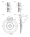
- a circular cutting knife or disk-shaped knife 1 is shown in elevation, with a central axis 2, which can be attached to the rotatable shaft of the cutting device.
- the cutting knife 1 has a diameter of 63 mm and is delimited on its end face 3 by a flat hollow cone which has a cone angle of e.g. 170 °. Accordingly, in Fig. 4 the clearance angle ⁇ is e.g. 5 °.
- the limitation by the hollow cone mentioned takes place only in the area of the cutting knife 1 near the edge, which is further excluded towards the center in order to form an outlet for the grinding tool shown in FIGS. 4 and 6.
- the cutting knife 1 is drilled out in the middle in order to receive a stub shaft which in turn must not protrude beyond the end face 3.
- a nut in the left central expansion in FIGS. 1 and 2 is used for fastening.
- the end face is provided with a plane recess 31, which extends up to the teeth and serves as an outlet for a grinding tool 35.
- the cutting knife 1 has 22 teeth on its circumference, the tooth back 9 of which points both in and against the direction of rotation (see FIG. 3) are each formed as a sharp cutting edge.
- the lateral tooth flanks are each formed on the bottom and rear of the cutting knife 1 as adjacent, flat surfaces 30 which are inclined at an angle to one another.
- narrow strips remain from the original end face 3, which have essentially parallel edges, extend from the tooth tips 34 and run towards the center of the cutting knife.
- the surfaces 30 are flat, in order to leave a pronounced depression in the outer contour of the cutting knife between the tooth tips 34, they must be inclined at an angle to one another, this inclination being formed such that they adjoin one another in a straight line track 31, which of the Center of the depression between two adjacent teeth 34 extends and is directed towards the center of the cutting knife.
- the tooth back or cutting edges 9 do not run exactly in the circumferential direction of the cutting knife, but only the tooth tips 34 lie on the conical surface 3, while the cutting edges, starting from this, are slightly inclined towards the rear of the cutting knife.
- the surfaces 30 are not only inclined in relation to a radial plane with respect to the central axis of the cutting knife in the circumferential direction, but also towards the axis. This inclination can be seen from FIG. 4 and is arranged in such a way that each of the cutting edges is set back against a radial plane corresponding to the angle of the cone 3 by a clearance angle ⁇ , which is preferably of the order of 5 °, while the front and rear sides the cutting edges together form a cutting angle a of approximately 25 °.
- the back of the teeth is formed by two ablation surfaces arranged at an angle to one another, which are inclined at the same angle to one another as the end surfaces 30, so that the same tool 35 is used for their production can, which will be discussed further below.
- the surfaces are arranged in such a way that they also adjoin one another directly in the area of the tooth syringes and thus form a straight line, starting from the tooth tips 34 and pointing towards the axis.
- the tooth tips 34 therefore only have the strips 3 ′ running towards the axis on the front, while a sharp edge runs towards the axis on the back of the tooth.
- the two adjoining surfaces on the rear of the cutting knife form a straight line starting from the center of this depression and pointing towards the axis.
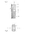
- FIG. 4 The manufacture of the incisors is shown in FIG. 4: a grinding wheel 35 is used for the manufacture, the cross section of which is symmetrically roof-shaped and has an apex angle y of approximately 168 ° (see FIG. 6). This grinding wheel 35 is moved in directions which are shown by arrows in FIG. 4 and correspond to the two inclination directions defining the cutting angle a. As a result of the roof-shaped cross section of the grinding wheel 35, two adjacent surfaces 30 on the end face or corresponding surfaces on the rear side are ground in one operation, each of which lies between two adjacent tooth tips. Only a single tool 35 is thus required to insert the teeth into the pre-turned and pre-ground blank.
- a side milling cutter 5 Adjacent to the cutting knife 1 and coaxially with it, a side milling cutter 5 is attached to the rotary shaft (not shown) (FIG. 1).
- the cylindrical side milling cutter 5 has milling teeth 6 on its outer circumference.
- the disk milling cutter 5 lies directly against the cutting knife 1 and is frustoconically cut out on its surface facing it, so that its edges of the cutting teeth 6 facing the cutting knife touch the flanks of the cutting teeth 10 completely or almost.
- the outer circumference of the side milling cutter 5 is smaller than that of the cutting knife 1, but larger than the root circle of the cutting teeth facing it.
- the root circle of the side milling cutter 5 is smaller than that of the incisors.
- the milling teeth 6 can run obliquely or spirally.
- FIG. 2 shows the same cutting knife as in FIG. 1, however the side milling cutter 5 is replaced by a deflecting roller 7.
- This deflecting roller has the same connection and installation dimensions as the side milling cutter 5 of FIG. 1, but is on its circumference formed by a smooth fillet 8, which has such an inner profile that with continuous extension of the inner profile of the fillet 8 in the direction of the cutting knife 1, the extension cuts the tooth tips.
- the deflecting roller 7 is independent of the direction of rotation of the cutting knife 1, which, as can be seen from FIG. 3, can then rotate in opposite directions without therefore deteriorating the cutting action.
- the disk milling cutter 5 preferably has teeth which, like the teeth of the cutting knife 1, have a gradually increasing tooth depth or tooth height on their tooth flank pointing in the direction of movement.
- the side milling cutter or chip breaker which is ground on an incline, has 12 teeth and has either right-hand or un-twist.
- the fillet 8 of the deflection roller 7 preferably has a radius of approximately 10 mm and runs out on its side facing the cutting knife 1 at an angle of 20 ° with respect to a radial plane.
- the diameter of the deflecting roller or the side milling cutter is advantageously 3 to 5% smaller than that of the cutting knife 1.
- the tooth depth of the side milling cutter 5 is approximately 4.5 mm.
- FIG. 5 shows a further deflector 17, the general structure and dimensions of which correspond approximately to those of the deflector 5 of FIG. 1 and the deflector 7 of FIG. 2.
- the deflector 17 of FIG. 5 can also be inscribed in a circular cylinder, but instead of the milling teeth 6 of the deflector 5 of FIG. 1, spirally or obliquely extending teeth 18 are provided.
- a fine thread 19 is cut into the outer circumference of the spiral or helical toothed deflection device 17 and forms chip breaking grooves. The depth of the chipbreaking grooves 19 is approximately a quarter of the height of the teeth 18.
- the teeth drop steeply towards the base of the tooth, while on the back flank they fall relatively flat.
- the first-mentioned, steeply falling tooth face extends to the outer circumference of the deflection device, the rear tooth flank merging into an oblique grinding surface 20 which adjoins the tooth cutting edge.
- the fine thread that forms the chipbreaking grooves 19 has a division of e.g. 1 to 2 mm.
- the deflector 17 carries 30 oblique teeth.
Landscapes
- Life Sciences & Earth Sciences (AREA)
- Forests & Forestry (AREA)
- Engineering & Computer Science (AREA)
- Mechanical Engineering (AREA)
- Wood Science & Technology (AREA)
- Crushing And Pulverization Processes (AREA)
Applications Claiming Priority (2)
| Application Number | Priority Date | Filing Date | Title |
|---|---|---|---|
| DE3510074 | 1985-03-20 | ||
| DE19853510074 DE3510074A1 (de) | 1985-03-20 | 1985-03-20 | Schneidvorrichtung fuer wabenfoermige leichtbaukoerper |
Publications (3)
| Publication Number | Publication Date |
|---|---|
| EP0199062A2 true EP0199062A2 (fr) | 1986-10-29 |
| EP0199062A3 EP0199062A3 (en) | 1988-12-28 |
| EP0199062B1 EP0199062B1 (fr) | 1991-03-20 |
Family
ID=6265810
Family Applications (1)
| Application Number | Title | Priority Date | Filing Date |
|---|---|---|---|
| EP86103395A Expired - Lifetime EP0199062B1 (fr) | 1985-03-20 | 1986-03-13 | Dispositif pour couper des structures en nids d'abeilles |
Country Status (2)
| Country | Link |
|---|---|
| EP (1) | EP0199062B1 (fr) |
| DE (2) | DE3510074A1 (fr) |
Cited By (1)
| Publication number | Priority date | Publication date | Assignee | Title |
|---|---|---|---|---|
| CN113477997A (zh) * | 2021-07-27 | 2021-10-08 | 杭州电子科技大学 | 一种加工吸波蜂窝的超声弧刃锯片铣刀 |
Families Citing this family (2)
| Publication number | Priority date | Publication date | Assignee | Title |
|---|---|---|---|---|
| DE20104395U1 (de) * | 2001-03-10 | 2001-07-26 | didia Diamanttechnik GmbH, 95032 Hof | Segmente für maschinelle Schneid- und Trennwerkzeuge |
| DE10144119A1 (de) * | 2001-09-08 | 2003-03-27 | Bemo Elementbau Gmbh & Co Kg | Halteelement zur Halterung von Profiltafeln |
Family Cites Families (5)
| Publication number | Priority date | Publication date | Assignee | Title |
|---|---|---|---|---|
| DE668970C (de) * | 1935-07-28 | 1939-03-17 | Friedrich Von Traitteur | Messer zum Zertrennen von Papierbahnen und Bogen |
| DE964031C (de) * | 1955-01-25 | 1957-05-16 | Franz Balke | Messer mit feinverzahnter Schneide |
| US2929299A (en) * | 1958-03-13 | 1960-03-22 | Martin Co | Cutting tool |
| FR1479493A (fr) * | 1966-03-15 | 1967-05-05 | Jurine Soc | Perfectionnements aux procédés et machines pour fendre ou rainurer les feuilles decarton et analogues |
| DE3334165C2 (de) * | 1983-09-21 | 1996-09-26 | Prototyp Werke Gmbh | Schneidvorrichtung für wabenförmige Leichtbaukörper |
-
1985
- 1985-03-20 DE DE19853510074 patent/DE3510074A1/de not_active Ceased
-
1986
- 1986-03-13 EP EP86103395A patent/EP0199062B1/fr not_active Expired - Lifetime
- 1986-03-13 DE DE8686103395T patent/DE3678190D1/de not_active Expired - Lifetime
Cited By (2)
| Publication number | Priority date | Publication date | Assignee | Title |
|---|---|---|---|---|
| CN113477997A (zh) * | 2021-07-27 | 2021-10-08 | 杭州电子科技大学 | 一种加工吸波蜂窝的超声弧刃锯片铣刀 |
| CN113477997B (zh) * | 2021-07-27 | 2022-06-10 | 杭州电子科技大学 | 一种加工吸波蜂窝的超声弧刃锯片铣刀 |
Also Published As
| Publication number | Publication date |
|---|---|
| DE3510074A1 (de) | 1986-09-25 |
| EP0199062B1 (fr) | 1991-03-20 |
| DE3678190D1 (de) | 1991-04-25 |
| EP0199062A3 (en) | 1988-12-28 |
Similar Documents
| Publication | Publication Date | Title |
|---|---|---|
| DE3313103C2 (fr) | ||
| DE3706855C2 (fr) | ||
| EP0334002B1 (fr) | Fraise de filetage | |
| DE3112639C2 (fr) | ||
| DE3334165C2 (de) | Schneidvorrichtung für wabenförmige Leichtbaukörper | |
| DE68923131T2 (de) | Bohrer, Schleifverfahren und Schleifvorrichtung. | |
| DE3022292C2 (de) | Verfahren und Vorrichtung zum Herstellen von Ausnehmungen in einem Werkstück | |
| EP4100186B1 (fr) | Outil de laminage et procédé de laminage d'un profilé | |
| DE2827145A1 (de) | Kugelfoermiger waelzfraeser zur herstellung von zahnraedern | |
| DE69218513T2 (de) | Hohlbohrer | |
| DE2821433C2 (de) | Verfahren zum Herstellen eines Schraubenrotors für eine Kompressions- od. Expansionsmaschine | |
| EP0542056A1 (fr) | Outil de coupe, spécialement fraise à fileter | |
| EP0916771B1 (fr) | Dent de fraisage pour le travail de la terre | |
| EP0199062B1 (fr) | Dispositif pour couper des structures en nids d'abeilles | |
| EP1958589B1 (fr) | Fraise dentaire | |
| DE821146C (de) | Scheibenfoermiger Fraeskopf und Fraesverfahren zum Verzahnen von Zahnraedern | |
| DE2943567A1 (de) | Reisszahnwalze und damit bestueckte reisswalenzerkleinerungsmaschinen | |
| EP0974255B1 (fr) | Faucheuse hélicoidale | |
| DE3334071C2 (fr) | ||
| DE3231341C2 (fr) | ||
| DE102004040580B4 (de) | Fräser | |
| DE2618254A1 (de) | Messertrommel, insbesondere fuer hackmaschinen zur zerkleinerung von hoelzern und abfaellen | |
| DE4444977A1 (de) | Zerkleinerungswerk, insbesondere für Hächsler zum Zerkleinern von Garten-/oder holzigem Abfall | |
| DE2539881A1 (de) | Zahnaerztliches drehwerkzeug, insbesondere fraeser | |
| DE4440480C2 (de) | Fräsbohrwerkzeug |
Legal Events
| Date | Code | Title | Description |
|---|---|---|---|
| PUAI | Public reference made under article 153(3) epc to a published international application that has entered the european phase |
Free format text: ORIGINAL CODE: 0009012 |
|
| AK | Designated contracting states |
Kind code of ref document: A2 Designated state(s): BE CH DE FR GB IT LI NL |
|
| PUAL | Search report despatched |
Free format text: ORIGINAL CODE: 0009013 |
|
| AK | Designated contracting states |
Kind code of ref document: A3 Designated state(s): BE CH DE FR GB IT LI NL |
|
| 17P | Request for examination filed |
Effective date: 19890124 |
|
| 17Q | First examination report despatched |
Effective date: 19890607 |
|
| GRAA | (expected) grant |
Free format text: ORIGINAL CODE: 0009210 |
|
| RAP3 | Party data changed (applicant data changed or rights of an application transferred) |
Owner name: PROTOTYP-WERKE GMBH, FABRIK FUER PRAEZISIONSWERKZE |
|
| AK | Designated contracting states |
Kind code of ref document: B1 Designated state(s): BE CH DE FR GB IT LI NL |
|
| ITF | It: translation for a ep patent filed | ||
| REF | Corresponds to: |
Ref document number: 3678190 Country of ref document: DE Date of ref document: 19910425 |
|
| GBT | Gb: translation of ep patent filed (gb section 77(6)(a)/1977) | ||
| ET | Fr: translation filed | ||
| PLBE | No opposition filed within time limit |
Free format text: ORIGINAL CODE: 0009261 |
|
| STAA | Information on the status of an ep patent application or granted ep patent |
Free format text: STATUS: NO OPPOSITION FILED WITHIN TIME LIMIT |
|
| 26N | No opposition filed | ||
| REG | Reference to a national code |
Ref country code: GB Ref legal event code: IF02 |
|
| PGFP | Annual fee paid to national office [announced via postgrant information from national office to epo] |
Ref country code: GB Payment date: 20050228 Year of fee payment: 20 |
|
| PGFP | Annual fee paid to national office [announced via postgrant information from national office to epo] |
Ref country code: DE Payment date: 20050309 Year of fee payment: 20 |
|
| PGFP | Annual fee paid to national office [announced via postgrant information from national office to epo] |
Ref country code: CH Payment date: 20050310 Year of fee payment: 20 |
|
| PGFP | Annual fee paid to national office [announced via postgrant information from national office to epo] |
Ref country code: FR Payment date: 20050311 Year of fee payment: 20 |
|
| PGFP | Annual fee paid to national office [announced via postgrant information from national office to epo] |
Ref country code: IT Payment date: 20050316 Year of fee payment: 20 |
|
| PGFP | Annual fee paid to national office [announced via postgrant information from national office to epo] |
Ref country code: NL Payment date: 20050322 Year of fee payment: 20 |
|
| PGFP | Annual fee paid to national office [announced via postgrant information from national office to epo] |
Ref country code: BE Payment date: 20050422 Year of fee payment: 20 |
|
| PG25 | Lapsed in a contracting state [announced via postgrant information from national office to epo] |
Ref country code: GB Free format text: LAPSE BECAUSE OF EXPIRATION OF PROTECTION Effective date: 20060312 |
|
| PG25 | Lapsed in a contracting state [announced via postgrant information from national office to epo] |
Ref country code: NL Free format text: LAPSE BECAUSE OF EXPIRATION OF PROTECTION Effective date: 20060313 |
|
| REG | Reference to a national code |
Ref country code: GB Ref legal event code: PE20 |
|
| REG | Reference to a national code |
Ref country code: CH Ref legal event code: PL |
|
| NLV7 | Nl: ceased due to reaching the maximum lifetime of a patent |
Effective date: 20060313 |
|
| BE20 | Be: patent expired |
Owner name: *PROTOTYP-WERKE G.M.B.H. FABRIK FUR PRAZISIONSWERK Effective date: 20060313 |