EP0199155B1 - Vorrichtung zum kontinuierlichen Schneiden von sich bewegenden Strängen, insbesondere Seifensträngen - Google Patents
Vorrichtung zum kontinuierlichen Schneiden von sich bewegenden Strängen, insbesondere Seifensträngen Download PDFInfo
- Publication number
- EP0199155B1 EP0199155B1 EP86104565A EP86104565A EP0199155B1 EP 0199155 B1 EP0199155 B1 EP 0199155B1 EP 86104565 A EP86104565 A EP 86104565A EP 86104565 A EP86104565 A EP 86104565A EP 0199155 B1 EP0199155 B1 EP 0199155B1
- Authority
- EP
- European Patent Office
- Prior art keywords
- strand
- cutting
- belt
- blade
- pieces
- Prior art date
- Legal status (The legal status is an assumption and is not a legal conclusion. Google has not performed a legal analysis and makes no representation as to the accuracy of the status listed.)
- Expired - Lifetime
Links
- 239000000344 soap Substances 0.000 title claims abstract description 5
- 239000012056 semi-solid material Substances 0.000 claims description 3
- 239000000463 material Substances 0.000 abstract description 2
- 238000010276 construction Methods 0.000 description 2
- KXGFMDJXCMQABM-UHFFFAOYSA-N 2-methoxy-6-methylphenol Chemical compound [CH]OC1=CC=CC([CH])=C1O KXGFMDJXCMQABM-UHFFFAOYSA-N 0.000 description 1
- 238000001514 detection method Methods 0.000 description 1
- 239000005011 phenolic resin Substances 0.000 description 1
- 229920001568 phenolic resin Polymers 0.000 description 1
- 229920000573 polyethylene Polymers 0.000 description 1
Images


Classifications
-
- B—PERFORMING OPERATIONS; TRANSPORTING
- B26—HAND CUTTING TOOLS; CUTTING; SEVERING
- B26D—CUTTING; DETAILS COMMON TO MACHINES FOR PERFORATING, PUNCHING, CUTTING-OUT, STAMPING-OUT OR SEVERING
- B26D7/00—Details of apparatus for cutting, cutting-out, stamping-out, punching, perforating, or severing by means other than cutting
- B26D7/06—Arrangements for feeding or delivering work of other than sheet, web, or filamentary form
- B26D7/0625—Arrangements for feeding or delivering work of other than sheet, web, or filamentary form by endless conveyors, e.g. belts
-
- C—CHEMISTRY; METALLURGY
- C11—ANIMAL OR VEGETABLE OILS, FATS, FATTY SUBSTANCES OR WAXES; FATTY ACIDS THEREFROM; DETERGENTS; CANDLES
- C11D—DETERGENT COMPOSITIONS; USE OF SINGLE SUBSTANCES AS DETERGENTS; SOAP OR SOAP-MAKING; RESIN SOAPS; RECOVERY OF GLYCEROL
- C11D13/00—Making of soap or soap solutions in general; Apparatus therefor
- C11D13/22—Cutting
Definitions
- the present invention relates to an automatic cutting machine for cutting into pieces a continuously advanced strand of an extruded semisolid material, particularly a strand of soap; whereby this machine comprises a conveyor belt arranged substantially horizontally, which is meant for carrying the continuous strand, the piece in the course of being cut, and the already cut pieces, a guillotine-type cutting unit being operatively associated with the said belt and being adapted for cutting the pieces directly on the belt itself, by using as opposing means the active stretch of the belt which is properly supported by an underlying stationary table for the sliding thereof, and whereby the said cutting unit comprises a blade fastenend to a supporting fork connected with reciprocatingly driving means fitted onto the fixed structure of the machine, the said fork being hingendly connected in such a manner that the blade is allowed to perform a motion of translation substantially parallel to the direction of the strand forward movement.
- a cutting machine of this kind is known from US-A 3 269 243.
- the invention aims to realize a machine of the aforementioned type which in combination with a very simple construction, permits to cut from the strand pieces of any desired, even very short length and with a very quick cutting sequence, and to deliver them to its outlet in a suitably spaced apart relation.
- the invention provides a machine of the aforementioned type, characterized by the combination of the following features:
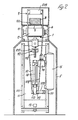
- FIG. 1 a cutting machine according to the invention, which is adapted for cutting pieces P of a predetermined length from an extruded strand B being continuously moved forward, which preferably is a strand of soap of any like semisolid material.
- the said cutting machine comprises a horizontal conveyor belt 1 which is led around two rollers 2 and 3 fitted between two opposite longitudinal sidewalls 4 carried by a box-shaped base frame 5 of the machine.
- the active stretch 101 of belt 1, i.e., the upper stretch thereof, that is meant for carrying both the strand B being fed thereon and the already cut pieces P, is in turn supported throughout its length by an underlying stationary table 6 made from a material with a low coefficient of sliding friction, such as, for example, from a suitable phenolic resin, on which the said stretch of the belt can easily slide.
- the roller 2 of the conveyor belt 1 is driven through a suitable chain drive 7 by a geared motor 8 housed in the box-shaped base frame 5, which causes the belt to be advanced in the direction of arrow F at a higher speed than the speed at which the strand B is fed thereon, in the concordant direction.
- This brings about a continuous sliding of the belt 1 relatively to the extruded strand B, chiefly in order to space apart the cut pieces P to be delivered from the machine.
- a cutting unit 9 of the guillotine type which is capable of cutting the strand B into pieces P directly on the belt itself, by using as opposing means the stretch 101 of the belt, that is properly supported by the table 6 for the sliding thereof.
- the said cutting unit 9 comprises a blade-carrying fork 109 arranged in a substantially vertical position astride of the belt 1, near its idle roller 3; at its upper end, above the belt 1, the said fork carries a cutting blade 209, and at its lower end it is swingably pivoted at 110 to the extremity of the piston rod of a double-acting pneumatic cylinder 10 which alternately moves the blade from a position in which it is quite removed from the stretch 101 of belt 1, into a position in which it grazes the said stretch of the belt.
- the pneumatic cylinder 10 is secured onto a plate 11 which is so mounted as to be adjustable along vertical guides 111 which are integral of the base frame 5, whereby it is possible to fix a priori the maximum distance of the blade 109 from the stretch 101 of belt 1, in correlation with the thickness of the strand B to be cut.
- the height adjustment of plate 11 and thus of blade 209 can be manually performed by using a simple mechanical device 12.
- the said device 12 comprises a threaded vertical stem 112 which is rotatably carried by the fixed structure of the machine, and is engaged in a respective threaded bushing 212 integral with the plate 11.
- the said threaded stem 112 is rotated through a pair of bevel gears driven by means of a handle 412.
- the blade-carrying fork 109 When in the waiting step, the blade-carrying fork 109 is in a quite vertical position, as shown by solid lines in Figure 1.
- the said blade-carrying fork is driven forward, as shown by dash-and-dot lines still in Figure 1, and is pivoted about the pivot 110, so that it causes the blade to describe an arc of a circle of a relatively great radius.
- provisions are made for the table 6 supporting the said stretch 101 of the belt, to be inclined downward by a small angle, which is sufficient for counterbalancing the slight sinking of the blade.
- a fixed limit stop member 13 is operatively associated with the cylinder 10, while the fork 109 has its lower end provided with a small flange 119, that is meant for hitting against an abutment member 129, whereby the fork will be returned, on completion of a cutting cycle, into waiting position.
- the pneumatic cylinder 10 is fed from a reservoir and plenum chamber 15, into which pressure air is admitted.
- the presence of the reservoir guarantees a delivery of air at a constant pressure from the cylinder 10.
- connection between the reservoir 15 and the cylinder 10 is accomplished by means of short connectors and only one pipe length 16, preferably of polythene.
- the solenoid valve 14 of the pneumatic cylinder 10 is actuated by a control device 17, shown particularly in Figures 3 and 4, which is adapted for detecting the forward movement of the strand B.
- the said control device comprises a supporting arm 18 shaped like an overturned “L”, which at its lower end is made integral of plate 11, and at its upper end carries two spaced apart, idle rollers 19 and 20, that are meant or bearing on the extruded strand B, so as to keep it against the underlying belt 1.
- a lever 21 On the shaft 120 of roller 20 there is freely swingably mounted a lever 21 that carries the real and proper detection and control unit.
- the said unit comprises a rolle 22 that is arranged intermediately of the other two rollers 19 and 20, and is meant for bearing on the strand B in a freely rockable manner, the said roller 22 being connected with a pulse generator 23 which in turn is connected to a totalizator 24, whereby the said totalizator transmits control signals to the solenoid valve 14, in correlation with the degree of forward movement of the strand B.
- the adjustment of the said control unit permits to obtain pieces P of any desired length.
- the return of the cutting unit 9 into waiting position is controlled by a microswitch 117 that is operatively associated with the fork 109.
- inlet rollers 25 At the inlet side of the machine there are provided two suitably spaced apart inlet rollers 25 with their axes arranged vertically, which are adapted for laterally guiding the extruded strand B.
- the cutting machine according to the invention furthermore comprises a transparent cover 26 to which a microswitch is connected, that stops the machine any time the cover is raised.
Landscapes
- Chemical & Material Sciences (AREA)
- Life Sciences & Earth Sciences (AREA)
- Engineering & Computer Science (AREA)
- Organic Chemistry (AREA)
- Mechanical Engineering (AREA)
- Chemical Kinetics & Catalysis (AREA)
- Oil, Petroleum & Natural Gas (AREA)
- Wood Science & Technology (AREA)
- Forests & Forestry (AREA)
- Detergent Compositions (AREA)
- Nonmetal Cutting Devices (AREA)
- Control Of Cutting Processes (AREA)
- Processing And Handling Of Plastics And Other Materials For Molding In General (AREA)
- Treatment Of Fiber Materials (AREA)
- Confectionery (AREA)
- Control And Other Processes For Unpacking Of Materials (AREA)
- Processing Of Stones Or Stones Resemblance Materials (AREA)
Claims (6)
Priority Applications (1)
| Application Number | Priority Date | Filing Date | Title |
|---|---|---|---|
| AT86104565T ATE51568T1 (de) | 1985-04-19 | 1986-04-03 | Vorrichtung zum kontinuierlichen schneiden von sich bewegenden straengen, insbesondere seifenstraengen. |
Applications Claiming Priority (2)
| Application Number | Priority Date | Filing Date | Title |
|---|---|---|---|
| IT1247885 | 1985-04-19 | ||
| IT12478/85A IT1186863B (it) | 1985-04-19 | 1985-04-19 | Taglierina automatica per il taglio in pezzi di una barra in avanzamento continuo in particolare di sapone e simili |
Publications (2)
| Publication Number | Publication Date |
|---|---|
| EP0199155A1 EP0199155A1 (de) | 1986-10-29 |
| EP0199155B1 true EP0199155B1 (de) | 1990-04-04 |
Family
ID=11140638
Family Applications (1)
| Application Number | Title | Priority Date | Filing Date |
|---|---|---|---|
| EP86104565A Expired - Lifetime EP0199155B1 (de) | 1985-04-19 | 1986-04-03 | Vorrichtung zum kontinuierlichen Schneiden von sich bewegenden Strängen, insbesondere Seifensträngen |
Country Status (7)
| Country | Link |
|---|---|
| EP (1) | EP0199155B1 (de) |
| JP (1) | JPS61244496A (de) |
| AT (1) | ATE51568T1 (de) |
| BR (1) | BR8601700A (de) |
| DE (1) | DE3670036D1 (de) |
| ES (1) | ES8701836A1 (de) |
| IT (1) | IT1186863B (de) |
Families Citing this family (3)
| Publication number | Priority date | Publication date | Assignee | Title |
|---|---|---|---|---|
| FR2679817B1 (fr) * | 1991-08-02 | 1994-02-04 | Georges Rochet | Dispositif de decoupe d'un pain de savon. |
| DE19602411C1 (de) * | 1996-01-24 | 1997-05-28 | Bosch Gmbh Robert | Vorrichtung zum Abtrennen von Einzelstücken |
| CN110744617B (zh) * | 2019-09-23 | 2021-02-12 | 重庆第二师范学院 | 一种花椒肥皂分切装置 |
Family Cites Families (7)
| Publication number | Priority date | Publication date | Assignee | Title |
|---|---|---|---|---|
| GB566756A (en) * | 1943-01-22 | 1945-01-12 | Walter Philip Williams | A machine for cutting soap or other relatively soft material |
| US2613618A (en) * | 1948-05-25 | 1952-10-14 | Sharp Albert | Cutting mechanism and extrusion nozzle for continuously moving plastic bars |
| US3269243A (en) * | 1965-07-09 | 1966-08-30 | Henry B Denker | Guillotine cutter for roll sheeter |
| JPS50132588A (de) * | 1974-04-06 | 1975-10-20 | ||
| JPS54143492U (de) * | 1978-03-30 | 1979-10-04 | ||
| DE3151017A1 (de) * | 1981-12-23 | 1983-06-30 | W. Antpöhler GmbH & Co KG, 4795 Delbrück | Maschine zum schneiden von teigstraengen in scheiben und verfahren zur gebaeckherstellung unter verwendung der maschine |
| US4442741A (en) * | 1982-09-07 | 1984-04-17 | Whittingham Thomas D | Meat log cutter |
-
1985
- 1985-04-19 IT IT12478/85A patent/IT1186863B/it active
-
1986
- 1986-04-03 AT AT86104565T patent/ATE51568T1/de not_active IP Right Cessation
- 1986-04-03 DE DE8686104565T patent/DE3670036D1/de not_active Expired - Lifetime
- 1986-04-03 EP EP86104565A patent/EP0199155B1/de not_active Expired - Lifetime
- 1986-04-16 BR BR8601700A patent/BR8601700A/pt unknown
- 1986-04-18 JP JP61088450A patent/JPS61244496A/ja active Granted
- 1986-04-18 ES ES554129A patent/ES8701836A1/es not_active Expired
Also Published As
| Publication number | Publication date |
|---|---|
| BR8601700A (pt) | 1986-12-16 |
| DE3670036D1 (de) | 1990-05-10 |
| ES554129A0 (es) | 1986-12-16 |
| IT8512478A0 (it) | 1985-04-19 |
| JPS61244496A (ja) | 1986-10-30 |
| JPH0433593B2 (de) | 1992-06-03 |
| ES8701836A1 (es) | 1986-12-16 |
| EP0199155A1 (de) | 1986-10-29 |
| ATE51568T1 (de) | 1990-04-15 |
| IT1186863B (it) | 1987-12-16 |
Similar Documents
| Publication | Publication Date | Title |
|---|---|---|
| US9021847B2 (en) | Luminous character enclosing machine | |
| JPS61262012A (ja) | 絶縁ワイヤの送り、切断、ストリツプ装置 | |
| US4457195A (en) | Automatic strip cutting machine | |
| US20030200848A1 (en) | Slicing-machine drive | |
| US5570728A (en) | Wire feeding and cutting machine | |
| US4444077A (en) | Flying saw apparatus | |
| US4702137A (en) | Automatic band-saw system | |
| US3977586A (en) | Severing of sections of a printed packaging strip | |
| GB1301043A (en) | Improvements in or relating to slicing machines | |
| EP0199155A1 (de) | Vorrichtung zum kontinuierlichen Schneiden von sich bewegenden Strängen, insbesondere Seifensträngen | |
| US3904190A (en) | Apparatus for feeding paperboard blanks | |
| US3759124A (en) | Automatic cut-off saw | |
| US3754491A (en) | Delivery and cutting apparatus for tape | |
| US4939967A (en) | Cut-off machine | |
| US4422357A (en) | Apparatus for advancing a predetermined length of strip-shaped material | |
| US3865288A (en) | Apparatus for manufacturing slide covers | |
| US4771668A (en) | Cutting an elongated member into sections | |
| JP2600008B2 (ja) | スライサー | |
| GB2109585A (en) | Method and apparatus for controlling the upper limit of a cutting blade in cutting machines | |
| US3194101A (en) | String cutter having reciprocating gripper means to feed strings to the cutter | |
| US2549519A (en) | Chain cutting machine | |
| US3947920A (en) | Machine for separating meat tissue from bone | |
| US3112680A (en) | Device for producing windowed packages | |
| CN224116311U (zh) | 一种便于调节的塑料吸管自动裁切设备 | |
| US311421A (en) | Circular sawing machine |
Legal Events
| Date | Code | Title | Description |
|---|---|---|---|
| PUAI | Public reference made under article 153(3) epc to a published international application that has entered the european phase |
Free format text: ORIGINAL CODE: 0009012 |
|
| AK | Designated contracting states |
Kind code of ref document: A1 Designated state(s): AT BE CH DE FR GB LI LU NL SE |
|
| 17P | Request for examination filed |
Effective date: 19870130 |
|
| 17Q | First examination report despatched |
Effective date: 19880426 |
|
| GRAA | (expected) grant |
Free format text: ORIGINAL CODE: 0009210 |
|
| AK | Designated contracting states |
Kind code of ref document: B1 Designated state(s): AT BE CH DE FR GB LI LU NL SE |
|
| PG25 | Lapsed in a contracting state [announced via postgrant information from national office to epo] |
Ref country code: SE Effective date: 19900404 Ref country code: NL Effective date: 19900404 Ref country code: BE Effective date: 19900404 Ref country code: AT Effective date: 19900404 |
|
| REF | Corresponds to: |
Ref document number: 51568 Country of ref document: AT Date of ref document: 19900415 Kind code of ref document: T |
|
| REF | Corresponds to: |
Ref document number: 3670036 Country of ref document: DE Date of ref document: 19900510 |
|
| ET | Fr: translation filed | ||
| NLV1 | Nl: lapsed or annulled due to failure to fulfill the requirements of art. 29p and 29m of the patents act | ||
| PLBE | No opposition filed within time limit |
Free format text: ORIGINAL CODE: 0009261 |
|
| STAA | Information on the status of an ep patent application or granted ep patent |
Free format text: STATUS: NO OPPOSITION FILED WITHIN TIME LIMIT |
|
| 26N | No opposition filed | ||
| PG25 | Lapsed in a contracting state [announced via postgrant information from national office to epo] |
Ref country code: LU Free format text: LAPSE BECAUSE OF NON-PAYMENT OF DUE FEES Effective date: 19910430 |
|
| PGFP | Annual fee paid to national office [announced via postgrant information from national office to epo] |
Ref country code: CH Payment date: 19950306 Year of fee payment: 10 |
|
| PGFP | Annual fee paid to national office [announced via postgrant information from national office to epo] |
Ref country code: DE Payment date: 19950403 Year of fee payment: 10 |
|
| PG25 | Lapsed in a contracting state [announced via postgrant information from national office to epo] |
Ref country code: LI Effective date: 19960430 Ref country code: CH Effective date: 19960430 |
|
| REG | Reference to a national code |
Ref country code: CH Ref legal event code: PL |
|
| PG25 | Lapsed in a contracting state [announced via postgrant information from national office to epo] |
Ref country code: DE Effective date: 19970101 |
|
| PGFP | Annual fee paid to national office [announced via postgrant information from national office to epo] |
Ref country code: GB Payment date: 19980227 Year of fee payment: 13 |
|
| PG25 | Lapsed in a contracting state [announced via postgrant information from national office to epo] |
Ref country code: GB Free format text: LAPSE BECAUSE OF NON-PAYMENT OF DUE FEES Effective date: 19990403 |
|
| PGFP | Annual fee paid to national office [announced via postgrant information from national office to epo] |
Ref country code: FR Payment date: 19991029 Year of fee payment: 14 |
|
| GBPC | Gb: european patent ceased through non-payment of renewal fee |
Effective date: 19990403 |
|
| PG25 | Lapsed in a contracting state [announced via postgrant information from national office to epo] |
Ref country code: FR Free format text: LAPSE BECAUSE OF NON-PAYMENT OF DUE FEES Effective date: 20001229 |
|
| REG | Reference to a national code |
Ref country code: FR Ref legal event code: ST |