EP0199190B1 - Elément de séparation pour séparer des particules solides en suspension dans un courant gazeux par force centrifuge dans une chambre à tourbillon cylindrique - Google Patents
Elément de séparation pour séparer des particules solides en suspension dans un courant gazeux par force centrifuge dans une chambre à tourbillon cylindrique Download PDFInfo
- Publication number
- EP0199190B1 EP0199190B1 EP86104861A EP86104861A EP0199190B1 EP 0199190 B1 EP0199190 B1 EP 0199190B1 EP 86104861 A EP86104861 A EP 86104861A EP 86104861 A EP86104861 A EP 86104861A EP 0199190 B1 EP0199190 B1 EP 0199190B1
- Authority
- EP
- European Patent Office
- Prior art keywords
- separator
- air
- flow
- residual
- passages
- Prior art date
- Legal status (The legal status is an assumption and is not a legal conclusion. Google has not performed a legal analysis and makes no representation as to the accuracy of the status listed.)
- Expired - Lifetime
Links
- 239000007787 solid Substances 0.000 title claims description 3
- 239000002245 particle Substances 0.000 title 1
- 238000007789 sealing Methods 0.000 claims description 6
- ORQBXQOJMQIAOY-UHFFFAOYSA-N nobelium Chemical compound [No] ORQBXQOJMQIAOY-UHFFFAOYSA-N 0.000 description 4
- JTJMJGYZQZDUJJ-UHFFFAOYSA-N phencyclidine Chemical class C1CCCCN1C1(C=2C=CC=CC=2)CCCCC1 JTJMJGYZQZDUJJ-UHFFFAOYSA-N 0.000 description 4
- 239000000428 dust Substances 0.000 description 3
- IHQKEDIOMGYHEB-UHFFFAOYSA-M sodium dimethylarsinate Chemical class [Na+].C[As](C)([O-])=O IHQKEDIOMGYHEB-UHFFFAOYSA-M 0.000 description 3
- 238000005192 partition Methods 0.000 description 2
- 238000010276 construction Methods 0.000 description 1
- 238000012986 modification Methods 0.000 description 1
- 230000004048 modification Effects 0.000 description 1
- 230000002093 peripheral effect Effects 0.000 description 1
- 238000011144 upstream manufacturing Methods 0.000 description 1
Images


Classifications
-
- B—PERFORMING OPERATIONS; TRANSPORTING
- B01—PHYSICAL OR CHEMICAL PROCESSES OR APPARATUS IN GENERAL
- B01D—SEPARATION
- B01D45/00—Separating dispersed particles from gases or vapours by gravity, inertia, or centrifugal forces
- B01D45/12—Separating dispersed particles from gases or vapours by gravity, inertia, or centrifugal forces by centrifugal forces
-
- B—PERFORMING OPERATIONS; TRANSPORTING
- B04—CENTRIFUGAL APPARATUS OR MACHINES FOR CARRYING-OUT PHYSICAL OR CHEMICAL PROCESSES
- B04C—APPARATUS USING FREE VORTEX FLOW, e.g. CYCLONES
- B04C3/00—Apparatus in which the axial direction of the vortex flow following a screw-thread type line remains unchanged ; Devices in which one of the two discharge ducts returns centrally through the vortex chamber, a reverse-flow vortex being prevented by bulkheads in the central discharge duct
- B04C3/04—Multiple arrangement thereof
Definitions
- Separator element for separating solids suspended in a gas stream by centrifugal force in cylindrical swirl chambers.
- the invention relates to a separator element according to the preamble of claim 1.
- the raw air inlet and the residual gas outlet are formed in opposite end walls of the separator element.
- the outlets open into a common chamber, which is provided with a collecting outlet and is opposite an inlet chamber. Such an arrangement is unsuitable for confined spaces.
- Multicyclones are also known, in which a plurality of individual cyclones are connected in parallel (US-A-35 43 931).
- separate air guide housings are provided in the area of the inlet plane, lying transversely to the inlet plane, the inlet and outlet of which open on one side of the multicyclone in a plane parallel to the axis of the cyclones.
- the residual air flow is drawn off in the outlet plane of the cyclones opposite the inlet plane of the cyclones via an outlet housing.
- a pipe is connected to the outlet housing with which the residual air is discharged.
- the object of the invention is to provide a separator element of the generic type in such a way that the separators constructed therewith require a minimum of space and space-consuming pipelines.
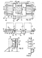
- the separator elements 2 are accordingly provided with a plurality of flow channels 4 and each with a plurality of cylindrical swirl chambers 6.
- the vortex chambers each adjoin the flow channels with a trailing edge and a leading edge. Between the trailing edge and leading edge, the swirl chambers are open on part of their wall surface to the flow channel.
- the swirl chambers are each provided with two clean gas outlet tubes 8, which are arranged coaxially in the swirl chambers and each extend from their end walls to one another.
- the cross-section of the flow channels is reduced in the flow direction from vortex chamber to vortex chamber so that the rate of entry of the gas flow into each of the successive vortex chambers is essentially the same.
- the inlets 10 of the flow channels lie in a connection plane 14 which is essentially transverse to the flow channels.
- the flow channels behind the last swirl chamber in the direction of flow open into a residual air channel 12, which within the separator element is essentially parallel to the flow channels 4 to the connection plane 14 of the Separator element is returned and has an opening 16 in it, which is at a distance from the inlets 10 of the flow channels 4.
- the flow channels in the separator element can be curved in a known manner in a wave-like manner and the swirl chambers can each be connected to the flow channels in the concave region thereof.
- the separator element is expediently divided in its longitudinal direction transverse to the axis of the swirl chambers, preferably symmetrically.
- the pipes 8 suitably consist of one part with the parts of the separator element.
- attachment flanges 18 are provided on the connecting plane 14 adjacent to the long sides of the separator element with a rectangular cross section, with which the separator elements are fastened to the housing of an inlet / outlet distributor 21.
- two separator elements 2 are arranged next to one another on the distributor 21 such that their broad sides are parallel to one another.
- the separator elements are enclosed on the outside at a distance from a housing 20 which is sealingly connected to the distributor 21, preferably in the same plane in which the separator elements are connected to the distributor.
- the housing 20, into which the clean gas outlet pipes 8 of the separator elements open, is provided with a clean air outlet connection 22, which is formed here on the end wall opposite the distributor 21.
- the clean air outlet connection can also be arranged at any other point. The arrangement essentially depends on the space available.
- the distributor 21 is provided with an unfiltered air inlet nozzle 24 which extends downward to the connection plane 14, so that the entire height of the inlets 10 of the flow channels 4 is covered.
- the inlet connection to the connecting plane 14 is subsequently provided with a separating rib 26, against which the two separator elements bear with their two adjacent longitudinal sides in a sealing manner and on which they are held in a sealing manner via the fastening flanges 18.
- a residual gas outlet connector 28 is formed below the unfiltered air inlet connector 24 and is connected to the orifices 16 of the residual air channels 12 of the two separator elements 2 via a trouser-shaped distributor 30.
- a suction fan 32 is shown placed on the outlet port 28. The residual air enriched with dust is extracted and discharged via this suction fan.
- Another fan, not shown, is connected upstream of the inlet port 24 to convey the unfiltered air through the filter elements.
- inlet connection 24 and outlet connection lie within the projection of the cross section of the housing 20, as a result of which a very compact design is achieved.
- the pants-shaped distributor 30 could of course also be arranged horizontally or directed downwards. It is essential that both the raw air supply and the removal of the residual air with the dust enriched therein are arranged on the same side of the housing 20, which means that complicated pipelines are unnecessary in many applications.
- two separator elements 2 are again provided, which are designed essentially in the same way as the separator elements described above, with raw air inlets 10 adjoining the connection side and each with a residual air duct 12 opening in the same plane.
- the two separator elements 2 are arranged here with their broad sides in one plane, ie they adjoin one another with their narrow sides, so that an extremely flat separator is achieved.
- the inlet-outlet distributor 32 is here provided with an inlet connection 34 which merges into a trouser-shaped channel 36 with a central separating rib 38 between the unfiltered air inlets 10 of the two separator elements 2.
- an outlet connection 40 is provided, which is also shown with a mounting flange and which is connected to a residual air collecting duct 42 which is guided below the level of the connection sides of the separator elements 2 and which is in the distributor 32 'below the trouser-shaped inlet duct 36 for the Raw air is guided.
- the right leg 44 in FIG. 5 has a substantially U-shaped, en course, the right leg 44 in FIG. 5 extending upward in the region of the separating rib 38 and provided with an opening opening in the connection plane 46 is located in front of the mouth of the residual air channel 12 of the right separator element.
- the second leg 48 of the residual air collecting duct 42 extends to the left of the outlet connection 40 upwards and likewise has an opening directed towards the connection plane, which is located in front of the mouth of the residual air duct 12 of the left separator element 2. It is also possible to provide the two upwardly directed legs 44 and 48 next to one another in the region of the rib 38 and to use the separator elements in such a way that their residual air channels are adjacent.
- the two separator elements 2 are in turn enclosed by a housing 50, which rests sealingly against a peripheral flange 52 of the distributor 32 and, as shown in FIG. 7, is provided with a downward opening 54 through which the clean air exits.
- This opening 54 can be a direct connection to the space to be supplied with the clean air or a large volume clean gas line. Blowers can be flanged directly to the connecting flanges of the connecting pieces 34, 40. Pipelines can also be connected.
- connection and distributor housings which are arranged centrally between two separator elements facing one another with their unfiltered air inlets or residual air outlets.
- the two figures show two different embodiments, an embodiment with separate clean air removal being provided for each of the two separator elements on the left, while an embodiment with a central one is shown on the right Clean air discharge is shown.
- the connection and distributor housings are mirror-symmetrical to the center line.
- the centrally arranged distributor housing 56 is provided on both sides with flat connection surfaces 58, which are parallel to one another and in which there is a dirty air inlet 60 and a residual air outlet 62.
- the raw air inlet 60 communicates with an inlet port 64 which is arranged at one end of the housing 56.
- An inlet 66 is provided opposite the inlet connection 64, to which the two opposite residual air outlets 62 are connected. In the exemplary embodiment shown, this outlet 66 opens coaxially or axially parallel with or to the inlet connector 64.
- the distributor housing is shown here with an outlet connector 68 flanged in front of the outlet 66 with an outlet directed downward.
- a clean air outlet connection 72 is provided, which opens here into a connection connection 74 of a housing 76, on which the separator is supported and fastened via a support bracket 78.
- the clean air outlet connection provided on the right of the center line is connected in the same way to the housing 76.
- the distributor housing 63 is designed essentially in the same way as in the embodiment shown on the left of the center line and described above.
- the connection piece 65 is somewhat higher here.
- a central clean air outlet connecting piece 80 is provided here, which is connected via a collecting duct 82 to a transverse opening 84 in the mutually opposite connecting walls of the distributor housing 56.
- This opening 84 is in each case connected to the interior of the housing 88 enclosing the separator element, which here, as shown on the right in FIG. 8, has a somewhat higher overall height in order to have the necessary flow cross section available on the underside of the separator element.
- the housing 86 is designed here in such a way that its end wall 88 lying opposite the distributor housing lies directly against the end wall of the separator element 2.
- the necessary flow cross-section for the clean air emerging on the upper side is achieved here by widening 90 of the housing 86 on both sides.
- the end of the separator element facing away from the distributor housing 56 is at a distance from the end wall of the housing, so that here a sufficient flow cross section is available for the clean air emerging at the top.
- a holding and distributor element 102 for the construction of a large separator system is shown, which is housed in a container 100.
- the distributor element 102 is designed as a plate 104, which can be inserted sealingly into an opening in a wall 106, which separates a chamber 108 into the container 100, into which raw air is conveyed, from a chamber 105 into which the clean air exits.
- 13 shows a cross section through such a container, for example.
- Four holding and distributing elements 102 are inserted one above the other in openings in the wall 106, as shown in FIGS. 10 to 12.
- the dust-containing raw air is blown or sucked in via a blower, not shown, via the connection shown here on the underside of the container, while clean air from the separator elements exits into the clean-air collecting chamber 110, which is on the right of the partition wall 106, with a Clean air outlet 109 is provided.
- the residual air collection ducts of the holding and distributor element 102 are connected to a common residual air outlet line 112, which is sealingly guided, for example, through the bottom of the container to the outside, wherein a fan for the residual air delivery can be arranged inside the room 108, but also outside the container.
- a large number of separator elements 2 are connected to the plate 104 on the rear side.
- three rows A, B and C of separator elements are each arranged with their broad sides parallel to one another, with five separator elements each in rows A and C and four separator elements in row B.
- Window-like openings 114 are provided in the plate 104 and are separated from one another by webs 116. These openings 114 are essentially congruent with the unfiltered air inlets 10 of the separator elements.
- openings 118 are provided, of which only one opening is shown, for example, for each of the rows A to C in the drawing. This opening coincides with the mouth of the residual air duct of the separator elements 2.
- these openings 118 are adjacent, i.e. the separator elements are arranged here in such a way that the residual air outlet channels run at their adjacent longitudinal edges.
- two residual air collecting channels 120, 122 are provided at a distance, which are connected to one another at their lower end and are provided with a residual air outlet connection 126 within the horizontal connection 124.
- this residual air outlet connection 126 can be designed with a horizontal axis. But it can also be inclined downwards.
- the connecting pieces 126 of a plurality of plates are connected to the common residual air discharge line 112. The unfiltered air can enter the separator elements directly from the space 108 via the window-like openings 116.
- a circumferential sealing groove 128 is provided on the rear side of the plate 104, and elongated holes 130 are also provided on the edge for receiving fastening screws.
- the entire plate is ribbed to increase rigidity.
- the separator elements are screwed with their fastening flanges 18 against the rear of the plate 104.
Landscapes
- Chemical & Material Sciences (AREA)
- Chemical Kinetics & Catalysis (AREA)
- Separating Particles In Gases By Inertia (AREA)
- Heterocyclic Carbon Compounds Containing A Hetero Ring Having Oxygen Or Sulfur (AREA)
Claims (5)
Applications Claiming Priority (2)
| Application Number | Priority Date | Filing Date | Title |
|---|---|---|---|
| DE3514275 | 1985-04-17 | ||
| DE3514275A DE3514275C1 (de) | 1985-04-17 | 1985-04-17 | Abscheiderelement zum Abscheiden von in einem Gasstrom suspendierten Feststoffen mittels Fliehkraft in zylindrischen Wirbelkammern |
Publications (3)
| Publication Number | Publication Date |
|---|---|
| EP0199190A2 EP0199190A2 (fr) | 1986-10-29 |
| EP0199190A3 EP0199190A3 (en) | 1988-07-20 |
| EP0199190B1 true EP0199190B1 (fr) | 1990-09-26 |
Family
ID=6268669
Family Applications (1)
| Application Number | Title | Priority Date | Filing Date |
|---|---|---|---|
| EP86104861A Expired - Lifetime EP0199190B1 (fr) | 1985-04-17 | 1986-04-09 | Elément de séparation pour séparer des particules solides en suspension dans un courant gazeux par force centrifuge dans une chambre à tourbillon cylindrique |
Country Status (2)
| Country | Link |
|---|---|
| EP (1) | EP0199190B1 (fr) |
| DE (2) | DE3514275C1 (fr) |
Family Cites Families (5)
| Publication number | Priority date | Publication date | Assignee | Title |
|---|---|---|---|---|
| GB374795A (en) * | 1932-01-01 | 1932-06-16 | William Alexander | Improvements in appliances for centrifugally purifying gases, vapours and steam |
| US3543931A (en) * | 1968-02-29 | 1970-12-01 | Nichols Eng & Res Corp | Multiple cyclone assembly |
| DE2743391A1 (de) * | 1977-09-27 | 1979-03-29 | Maschf Augsburg Nuernberg Ag | Wirbelkammer zur trennung von gasgemischen |
| DE3103842A1 (de) * | 1981-02-05 | 1982-09-09 | Anton Piller GmbH & Co KG, 3360 Osterode | Wirbelkammerfilter zum ausscheiden von feststoffen aus einem gasstrom |
| DE3203498C2 (de) * | 1981-02-05 | 1986-08-21 | Anton Piller GmbH & Co KG, 3360 Osterode | Abscheider für in einem Gasstrom suspendierte Feststoffe mittels Fliehkraft |
-
1985
- 1985-04-17 DE DE3514275A patent/DE3514275C1/de not_active Expired
-
1986
- 1986-04-09 DE DE8686104861T patent/DE3674447D1/de not_active Expired - Fee Related
- 1986-04-09 EP EP86104861A patent/EP0199190B1/fr not_active Expired - Lifetime
Also Published As
| Publication number | Publication date |
|---|---|
| DE3674447D1 (de) | 1990-10-31 |
| EP0199190A2 (fr) | 1986-10-29 |
| EP0199190A3 (en) | 1988-07-20 |
| DE3514275C1 (de) | 1986-09-25 |
Similar Documents
| Publication | Publication Date | Title |
|---|---|---|
| EP1541278B1 (fr) | Séparateur hydrocyclone | |
| DE2818791C2 (de) | Axial durchströmter Zyklonabscheider | |
| DE60201670T2 (de) | Trennvorrichtung mit zyklon | |
| DE60015304T2 (de) | Luftzufuhrmittel für einen zyklonenabscheider und staubsauger mit demselben | |
| DE102004028677B4 (de) | Wirbelungs-Abscheidungsvorrichtung und Staubsauger mit einer solchen Abscheidungsvorrichtung | |
| DE69524076T2 (de) | Luftfilteranordnung zum filtrieren von luft mit teilchen | |
| EP2201879A2 (fr) | Aspirateur doté des séparateurs de force centrifuge | |
| WO2018185268A1 (fr) | Séparateur multicyclones d'un filtre à fluide à plusieurs niveaux pour le nettoyage d'un fluide gazeux et filtre à fluide à plusieurs niveaux | |
| DE19734146A1 (de) | Luftzuführeinrichtung | |
| DE3103842A1 (de) | Wirbelkammerfilter zum ausscheiden von feststoffen aus einem gasstrom | |
| DE3815320C2 (de) | Staubsauger | |
| DE2343971B2 (de) | Gerät zur Fußbodenpflege | |
| AT395834B (de) | Vorrichtung zum entstauben von gasen | |
| DE1421310A1 (de) | Nassstaubabscheider | |
| AT395949B (de) | Filter zum reinigen eines gases | |
| DE3514275C1 (de) | Abscheiderelement zum Abscheiden von in einem Gasstrom suspendierten Feststoffen mittels Fliehkraft in zylindrischen Wirbelkammern | |
| EP0256491B1 (fr) | Dépoussiéreur centrifuge avec plusieurs cyclones | |
| DE3912077A1 (de) | Reinigungsmaschine | |
| DE4017229C2 (fr) | ||
| DE68905389T2 (de) | Luftfiltersatz für ein Industriefahrzeug. | |
| DE19651857C1 (de) | Vorrichtung zur Abscheidung von Feststoffen aus staubbeladenen Abgasen, insbesondere von Verbrennungsanlagen | |
| EP0254832A2 (fr) | Séparateur électrostatique de poussière | |
| EP0860192B1 (fr) | Dispositif de filtration | |
| DE553753C (de) | Fliehkraftstaubabscheider | |
| CH675366A5 (en) | Gravity separator appts. - for air borne paper snips, has several perforated air inlet sections |
Legal Events
| Date | Code | Title | Description |
|---|---|---|---|
| PUAI | Public reference made under article 153(3) epc to a published international application that has entered the european phase |
Free format text: ORIGINAL CODE: 0009012 |
|
| AK | Designated contracting states |
Kind code of ref document: A2 Designated state(s): DE FR GB IT |
|
| PUAL | Search report despatched |
Free format text: ORIGINAL CODE: 0009013 |
|
| AK | Designated contracting states |
Kind code of ref document: A3 Designated state(s): DE FR GB IT |
|
| 17P | Request for examination filed |
Effective date: 19880713 |
|
| 17Q | First examination report despatched |
Effective date: 19891027 |
|
| GRAA | (expected) grant |
Free format text: ORIGINAL CODE: 0009210 |
|
| AK | Designated contracting states |
Kind code of ref document: B1 Designated state(s): DE FR GB IT |
|
| ITF | It: translation for a ep patent filed | ||
| REF | Corresponds to: |
Ref document number: 3674447 Country of ref document: DE Date of ref document: 19901031 |
|
| ET | Fr: translation filed | ||
| GBT | Gb: translation of ep patent filed (gb section 77(6)(a)/1977) | ||
| ITTA | It: last paid annual fee | ||
| PLBE | No opposition filed within time limit |
Free format text: ORIGINAL CODE: 0009261 |
|
| STAA | Information on the status of an ep patent application or granted ep patent |
Free format text: STATUS: NO OPPOSITION FILED WITHIN TIME LIMIT |
|
| 26N | No opposition filed | ||
| PGFP | Annual fee paid to national office [announced via postgrant information from national office to epo] |
Ref country code: GB Payment date: 19940328 Year of fee payment: 9 |
|
| PGFP | Annual fee paid to national office [announced via postgrant information from national office to epo] |
Ref country code: FR Payment date: 19940330 Year of fee payment: 9 |
|
| PG25 | Lapsed in a contracting state [announced via postgrant information from national office to epo] |
Ref country code: GB Effective date: 19950409 |
|
| GBPC | Gb: european patent ceased through non-payment of renewal fee |
Effective date: 19950409 |
|
| PG25 | Lapsed in a contracting state [announced via postgrant information from national office to epo] |
Ref country code: FR Effective date: 19951229 |
|
| REG | Reference to a national code |
Ref country code: FR Ref legal event code: ST |
|
| PGFP | Annual fee paid to national office [announced via postgrant information from national office to epo] |
Ref country code: DE Payment date: 20030428 Year of fee payment: 18 |
|
| PG25 | Lapsed in a contracting state [announced via postgrant information from national office to epo] |
Ref country code: DE Free format text: LAPSE BECAUSE OF NON-PAYMENT OF DUE FEES Effective date: 20041103 |
|
| PG25 | Lapsed in a contracting state [announced via postgrant information from national office to epo] |
Ref country code: IT Free format text: LAPSE BECAUSE OF NON-PAYMENT OF DUE FEES Effective date: 20050409 |