EP0199216A2 - Sonde électro-encéphalographique comportant un câblage protégé contre les parasites - Google Patents
Sonde électro-encéphalographique comportant un câblage protégé contre les parasites Download PDFInfo
- Publication number
- EP0199216A2 EP0199216A2 EP86104988A EP86104988A EP0199216A2 EP 0199216 A2 EP0199216 A2 EP 0199216A2 EP 86104988 A EP86104988 A EP 86104988A EP 86104988 A EP86104988 A EP 86104988A EP 0199216 A2 EP0199216 A2 EP 0199216A2
- Authority
- EP
- European Patent Office
- Prior art keywords
- coaxial cables
- cables
- length
- eeg
- braid
- Prior art date
- Legal status (The legal status is an assumption and is not a legal conclusion. Google has not performed a legal analysis and makes no representation as to the accuracy of the status listed.)
- Withdrawn
Links
Images

Classifications
-
- A—HUMAN NECESSITIES
- A61—MEDICAL OR VETERINARY SCIENCE; HYGIENE
- A61B—DIAGNOSIS; SURGERY; IDENTIFICATION
- A61B5/00—Measuring for diagnostic purposes; Identification of persons
- A61B5/24—Detecting, measuring or recording bioelectric or biomagnetic signals of the body or parts thereof
- A61B5/30—Input circuits therefor
- A61B5/303—Patient cord assembly, e.g. cable harness
Definitions
- This invention relates to electroencephalographic (EEG) probe lead wiring, and more particularly to a lead wire for an EEG probe which minimizes the noise introduced into an EEG measuring system due to the wiring between an EEG probe and an amplifier of an evoked potential autorefractometry system.
- EEG electroencephalographic
- signals detected by the EEG probes are typically amplified by one million.
- Amplifiers for this purpose normally include very expensive low pass filters to filter out the noise picked up by the EEG probe and wiring between the probe and the amplifier.
- the amplifier amplifies the differential signals detected by the EEG probe by approximately one million, and because the amplitude of the signals detected by the EEG probe is similar to that of the noise due to the lead wires between the probe and the amplifier, it is essential that the lead wires introduce little if any noise into the measurement system.
- Twisting the lead wires into a twisted pair configuration minimizes the noise generated due to the loop area enclosed by the lead wires but, does not eliminate the noise due to triboelectric effects.
- the principle object of the invention is to provide a low noise EEG probe wiring system suitable for use in an evoked potential autorefractometry system.
- the present invention resides in a low noise electroencephalographic (EEG) probe wiring system for connection between an amplifier and at least a pair of EEG probes in an evoked potential autorefractometry system, comprising a pair of coaxial cables characterized by each of said cables having a central conductor having one end for connection to one of said pair of EEG probes and a second end for connection to said amplifier; a graphite coated polyethylene layer positioned around and bonded to the central conductor; a first braid shield positioned about the graphite coated layer along the length of said conductor, having a first end and a second end; a Teflon jacket positioned around said first braid shield along the length of said conductor; said coaxial cables being positioned substantially parallel and in contact with each other along a first segment of the length of said coaxial cables; a second braid shield having a first portion positioned around said pair of, coaxial cables and along said first segment, and a second portion positioned around respective ones of said coaxial cables along the remaining length of
- EEG electro
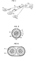
- a preferred embodiment of the present invention includes a pair of coaxial cables 50 and 55 of length L1 having central conductors 60 and 62.
- Each central conductor has a graphite coated insulating layer 65, a first braid shield 70, a second insulator layer 72, a second or external braid shield 75 and a third insulator layer 80.
- the pair of coaxial cables 50 and 55 are positioned in contact with each other for the entire length L2.
- a length of the EEG probe wiring system, L3, comprises the two coaxial cables 50 and 55 separated from each other. Minimizing the length L3 is necessary to minimize the loop noise pickup area defined by the separate coaxial cables 50 and 55.
- the length L3 should only be long enough to reach the area of the head to which an EEG is to be attached, for example, preferably no more than 4-6 inches.
- Fig. 3 illustrates a cross-sectional view along the line A-A of the coaxial cable 50 shown in Fig. 2.
- the coaxial cables 50 and 55 comprise "Micro Dot" coaxial cables part number LN-I manufactured by Mirotech, 1420 Conchester Hwy., Boothwyn, PA.
- a "Micro Dot" cable includes a central conductor 62 and a graphite coated polyethylene insulating layer 65 formed around and bonded to the central conductor 62.
- the outer surface of the insulating layer 65 facing the braid 70 is coated with graphite.
- the graphite coating is schematically represented by the area denoted by reference numeral 85.
- the graphite 85 eliminates the noise due to triboelectric effects, and substantially eliminates friction between the insulating layer 65 and the braid shield 70. For example, if the cable is bent, then the insulating layer 65 and braid shield 70 rub against each other in the region 90. This rubbing causes a charge to build up which capacitively couples to the central conductor 62 causing noise in the signal sought to be measured. Such a charge buildup is substantially eliminated by coating the insulating layer 65 with graphite. Rubbing between the central conductor 62 and the insulating layer 65, does not occur because the insulator is bonded to the center conductor.
- Rubbing between the insulating layer 65 and the braid shield 70 occurs not only when the cable is bent, but also when the cable incurs vibration due to, for example, machinery operating in a room next to the cable, or by people walking across the floor on which a cable is resting.
- the noise generated by such triboelectric effects significantly degrades the effectiveness of an EEG measuring system to the point where expensive signal processing equipment such as a high quality low pass filter must be employed to detect the EEG signals sought to be measured.
- the graphite coated insulating layer 65 minimizes and substantially eliminates these effects.
- the outside layer of the "Micro Dot" coaxial cable is the Teflon jacket 72.
- the EEG wiring system of the present invention is double shielded by the coaxial braid shield 70 and the external braid shield 75.
- These braid shields function to shield the central conductors 60 and 62 from electrostatic noise throughout the entire length, Ll, of the EEG probe wiring system from an amplifier 40 (Fig. 1) to the probes 20 and 25.
- a reference lead 95 is soldered to the external braid shield 75 and attached to the EEG probe 30.
- the EEG probe 30 is attached to, for example, the ear of a subject and provides a reference potential for measuring a differential voltage between the EEG probes 20 and 25.
- the reference lead could comprise a coaxial cable positioned within the braid shield 75.
- insulator layer 80 comprises heat shrink tubing.
- the heat shrink tubing is of a larger diameter than the coaxial cables 50, 55 and external braid shield 75 placed therein.
- a hand held dryer can be used to heat the tubing, causing it to shrink and mold itself around the braid shield 75 housing coaxial cables 50 and 55.
- the insulator layer 80 protects the braid shield 75 from contact with, for example, other exposed electrical connections typically found in a laboratory.
- the heat shrink tubing -80 also functions to hold the coaxial cables 50 and 55 in contact with each other throughout the entire length L3, as shown in Fig. 2.
- reference numeral 100 illustrates a cutaway view of an outer metal jacket for a gold contact metal plug used to connect the coaxial cables 50 and 55 to the amplifier 40.
- the broad shield 70 is connected to the gold reference contact of the metal jacket plug 100 and to the signal reference ground at the amplifier 40.
- the braid shield terminates within the metal jacket plug but is not electrically connected at the plug end.
- the metal jacket connects to the outer surface of the amplifier chassis. Use of the gold contact metal jacketed plug eliminates electrostatic noise due to friction between the plug and the amplifier connector 105.
- Fig. 4 is a cross-sectional view along the line B-B of the EEG probe wiring system shown in Fig. 2. As seen in Fig. 4, the composite cable has an oval shape. This shape results from the coaxial cables being placed adjacent to each other. Other shapes are possible depending upon, for example, whether or not the cables are formed in a twisted pair configuration or whether more than two coaxial cables are provided inside braid 75.
- the EEG probe wiring system of the present invention ensures that the coaxial cables 50 and 55 are held in contact with one another throughout the length L3 (Fig. 2), the noise due to the loop area enclosed by the cables is practically eliminated. Furthermore, double shielding the coaxial cables via braid shields 70 and 75 throughout the entire length of the cables from the amplifier 40 to the EEG probes 20 and 25; having no openings in the shield; electrically connecting braid shields 70 and 75 at the probes 20 and 25; and connecting inner shield 76 to the gold reference contact of the metal jacketed plug 100 at the amplifier 40 significantly minimizes any electrostatic noise that may enter the measuring system through the EEG probe wiring.
- the graphite coated insulating layer 65 substantially eliminates noise due to triboelectric effects created by bending the cable or due to cable vibrations induced by, for example, persons walking across the floor on which the cable is positioned, or by vibrations of a machine operating in a nearby room.
- the cables 50 and 55 can also be twisted in a twisted pair configuration within the braid shield 75 and heat shrink tubing 80 throughout the length L3. Such twisting provides further electrostatic and magnetic shielding. Such a configuration, however, is more difficult to place within the braid shield 75 and heat shrink tubing 80.
- coaxial cables being double shielded along their entire length, having graphite coated insulating layers and being positioned in contact with each other results in a low noise EEG probe wiring system that minimizes the noise due to (1) the area enclosed by the pair of coaxial cables, (2) electrostatic noise potentially picked up by the coaxial cables, (3) microphonic effects such as variable capacitance between the cables and bending and vibration of the cables, and (4) triboelectric effects such as bending.
Landscapes
- Life Sciences & Earth Sciences (AREA)
- Health & Medical Sciences (AREA)
- Medical Informatics (AREA)
- Animal Behavior & Ethology (AREA)
- Pathology (AREA)
- Engineering & Computer Science (AREA)
- Biomedical Technology (AREA)
- Heart & Thoracic Surgery (AREA)
- Physics & Mathematics (AREA)
- Molecular Biology (AREA)
- Surgery (AREA)
- Biophysics (AREA)
- General Health & Medical Sciences (AREA)
- Public Health (AREA)
- Veterinary Medicine (AREA)
- Measurement And Recording Of Electrical Phenomena And Electrical Characteristics Of The Living Body (AREA)
- Testing Of Individual Semiconductor Devices (AREA)
- Measuring Leads Or Probes (AREA)
- Ultra Sonic Daignosis Equipment (AREA)
Applications Claiming Priority (2)
| Application Number | Priority Date | Filing Date | Title |
|---|---|---|---|
| US06/727,060 US4678865A (en) | 1985-04-25 | 1985-04-25 | Low noise electroencephalographic probe wiring system |
| US727060 | 1985-04-25 |
Publications (2)
| Publication Number | Publication Date |
|---|---|
| EP0199216A2 true EP0199216A2 (fr) | 1986-10-29 |
| EP0199216A3 EP0199216A3 (fr) | 1989-03-08 |
Family
ID=24921170
Family Applications (1)
| Application Number | Title | Priority Date | Filing Date |
|---|---|---|---|
| EP86104988A Withdrawn EP0199216A3 (fr) | 1985-04-25 | 1986-04-11 | Sonde électro-encéphalographique comportant un câblage protégé contre les parasites |
Country Status (7)
| Country | Link |
|---|---|
| US (1) | US4678865A (fr) |
| EP (1) | EP0199216A3 (fr) |
| JP (1) | JPS61249438A (fr) |
| KR (1) | KR860007913A (fr) |
| CN (1) | CN86102854A (fr) |
| ES (1) | ES8707098A1 (fr) |
| MX (1) | MX161521A (fr) |
Cited By (4)
| Publication number | Priority date | Publication date | Assignee | Title |
|---|---|---|---|---|
| CN102215748A (zh) * | 2008-09-29 | 2011-10-12 | 阿瑟·舒尔茨 | 用于分析麻醉时eeg或特护eeg的方法和装置 |
| WO2013099185A1 (fr) * | 2011-12-28 | 2013-07-04 | Yazaki Corporation | Structure de ramification de câble |
| WO2018057047A1 (fr) * | 2016-09-26 | 2018-03-29 | Case Western Reserve University | Systèmes et procédés d'enregistrement prolongé de signaux neuronaux |
| WO2019057681A1 (fr) * | 2017-09-21 | 2019-03-28 | Koninklijke Philips N.V. | Conducteurs de surveillance de signal avec couvercles dissipatifs |
Families Citing this family (35)
| Publication number | Priority date | Publication date | Assignee | Title |
|---|---|---|---|---|
| US4973794A (en) * | 1987-07-31 | 1990-11-27 | General Electric Company | Cable assembly for an electrical signal transmission system |
| US4835394A (en) * | 1987-07-31 | 1989-05-30 | General Electric Company | Cable assembly for an electrical signal transmission system |
| US4992626A (en) * | 1989-10-12 | 1991-02-12 | The United States Of America As Represented By The Secretary Of The Army | Electrical cable for vehicles |
| US5175493A (en) * | 1991-10-11 | 1992-12-29 | Interconnect Devices, Inc. | Shielded electrical contact spring probe assembly |
| US5194838A (en) * | 1991-11-26 | 1993-03-16 | W. L. Gore & Associates, Inc. | Low-torque microwave coaxial cable with graphite disposed between shielding layers |
| FR2686729B1 (fr) * | 1992-01-29 | 1994-03-18 | Filotex | Liaison blindee multibranches. |
| FR2728113A1 (fr) * | 1994-12-13 | 1996-06-14 | Eurocopter France | Faisceau de conducteurs electriques blinde et son procede de realisation |
| US6075376A (en) | 1997-12-01 | 2000-06-13 | Schwindt; Randy J. | Low-current probe card |
| US5729150A (en) * | 1995-12-01 | 1998-03-17 | Cascade Microtech, Inc. | Low-current probe card with reduced triboelectric current generating cables |
| US6034533A (en) * | 1997-06-10 | 2000-03-07 | Tervo; Paul A. | Low-current pogo probe card |
| US6246006B1 (en) | 1998-05-01 | 2001-06-12 | Commscope Properties, Llc | Shielded cable and method of making same |
| US6384337B1 (en) | 2000-06-23 | 2002-05-07 | Commscope Properties, Llc | Shielded coaxial cable and method of making same |
| KR100864415B1 (ko) * | 2000-12-14 | 2008-10-20 | 가부시키가이샤 피지온 | 신체 임피던스 측정장치 |
| US7438976B2 (en) * | 2002-06-20 | 2008-10-21 | Ngx, Inc. | Nano-talc powders of high specific surface area obtained by hybrid milling |
| US20050048835A1 (en) * | 2003-08-27 | 2005-03-03 | Darren Clark | Coaxial cable splitter connector |
| USD512025S1 (en) * | 2004-03-04 | 2005-11-29 | Federal-Mogul World Wide, Inc. | Double tube |
| JP4477524B2 (ja) * | 2005-03-03 | 2010-06-09 | オリンパスメディカルシステムズ株式会社 | 検出装置および検出装置の製造方法 |
| US20070234789A1 (en) * | 2006-04-05 | 2007-10-11 | Gerard Glasbergen | Fluid distribution determination and optimization with real time temperature measurement |
| EP2240075B1 (fr) * | 2008-02-04 | 2011-08-03 | Koninklijke Philips Electronics N.V. | Connecteur d'electrode blinde |
| TW201102664A (en) * | 2009-07-15 | 2011-01-16 | Inventec Corp | Test probe |
| WO2011076819A2 (fr) * | 2009-12-24 | 2011-06-30 | Fci | Jonction de câble |
| JP5603650B2 (ja) * | 2010-05-10 | 2014-10-08 | オリンパス株式会社 | ケーブル接続構造及び内視鏡装置 |
| US8930143B2 (en) | 2010-07-14 | 2015-01-06 | Halliburton Energy Services, Inc. | Resolution enhancement for subterranean well distributed optical measurements |
| US8584519B2 (en) * | 2010-07-19 | 2013-11-19 | Halliburton Energy Services, Inc. | Communication through an enclosure of a line |
| JP5918968B2 (ja) * | 2011-11-02 | 2016-05-18 | 矢崎総業株式会社 | 電線分岐構造 |
| US20130240247A1 (en) * | 2012-03-14 | 2013-09-19 | R & D Circuits, Inc. | Apparatus and method for a conductive elastomer on a coaxial cable or a microcable to improve signal integrity probing |
| US9685717B2 (en) | 2012-03-14 | 2017-06-20 | R+D Sockets, Inc. | Apparatus and method for a conductive elastomer on a coaxial cable or a microcable to improve signal integrity probing |
| US9823373B2 (en) | 2012-11-08 | 2017-11-21 | Halliburton Energy Services, Inc. | Acoustic telemetry with distributed acoustic sensing system |
| CN103219576B (zh) * | 2013-05-07 | 2015-11-18 | 四川爱通电子线缆制造有限责任公司 | 一种射频同轴电缆的生产工艺 |
| US20150090491A1 (en) * | 2013-10-02 | 2015-04-02 | Tyco Electronics Corporation | Electrical cable assembly having an electrical shield |
| US10076279B2 (en) | 2013-10-22 | 2018-09-18 | Neba Health, Llc | System and method for a compact EEG headset |
| CN107233091A (zh) * | 2017-07-14 | 2017-10-10 | 陈晓苏 | 用于屏蔽电磁波的生物电信号采集装置 |
| US11779280B2 (en) | 2018-06-29 | 2023-10-10 | Biosense Webster (Israel) Ltd. | Reference wires to remove noise and artifacts in cardiac mapping catheter |
| CN109473221A (zh) * | 2018-11-15 | 2019-03-15 | 安徽宏源特种电缆集团有限公司 | 一种低噪音稳相同轴电缆 |
| US12052830B2 (en) | 2021-12-06 | 2024-07-30 | Advantest America, Inc. | Method and process for creating high-performance coax sockets |
Family Cites Families (12)
| Publication number | Priority date | Publication date | Assignee | Title |
|---|---|---|---|---|
| US2234068A (en) * | 1929-11-02 | 1941-03-04 | Okonite Co | Conductor |
| US2409033A (en) * | 1941-11-04 | 1946-10-08 | Garceau Lovett | Electroencephalograph device |
| US2622152A (en) * | 1946-09-21 | 1952-12-16 | Anaconda Wire & Cable Co | High attenuation coaxial cable |
| US3107152A (en) * | 1960-09-12 | 1963-10-15 | Union Carbide Corp | Fibrous graphite |
| US3433687A (en) * | 1966-06-17 | 1969-03-18 | Us Navy | Method of repairing low-noise transmission cable |
| US3669095A (en) * | 1966-08-25 | 1972-06-13 | Tokyo Shibaura Electric Co | Catheter-type semi-conductor radiation detector for insertion into a human body |
| DE2021172C3 (de) * | 1970-04-30 | 1974-06-12 | Kabel- Und Metallwerke Gutehoffnungshuette Ag, 3000 Hannover | Elektrisches Kabel für Hoch- und Höchstspannungsbeanspruchung, insbesondere mit Polyäthylenisolierung |
| JPS5642890Y2 (fr) * | 1975-03-22 | 1981-10-07 | ||
| US4122843A (en) * | 1977-08-10 | 1978-10-31 | Electro-Technics, Inc. | Electrode system for a heart rate monitor |
| US4374299A (en) * | 1980-05-19 | 1983-02-15 | Belden Corporation | Triboelectric transducer cable |
| US4404424A (en) * | 1981-10-15 | 1983-09-13 | Cooper Industries, Inc. | Shielded twisted-pair flat electrical cable |
| DE3337432A1 (de) * | 1983-10-14 | 1985-04-25 | Audioplan Renate Kühn, 7502 Malsch | Signalkabel |
-
1985
- 1985-04-25 US US06/727,060 patent/US4678865A/en not_active Expired - Lifetime
-
1986
- 1986-04-11 EP EP86104988A patent/EP0199216A3/fr not_active Withdrawn
- 1986-04-16 KR KR1019860002907A patent/KR860007913A/ko not_active Withdrawn
- 1986-04-22 JP JP61094380A patent/JPS61249438A/ja active Pending
- 1986-04-22 MX MX2270A patent/MX161521A/es unknown
- 1986-04-23 ES ES554296A patent/ES8707098A1/es not_active Expired
- 1986-04-24 CN CN198686102854A patent/CN86102854A/zh active Pending
Cited By (7)
| Publication number | Priority date | Publication date | Assignee | Title |
|---|---|---|---|---|
| CN102215748A (zh) * | 2008-09-29 | 2011-10-12 | 阿瑟·舒尔茨 | 用于分析麻醉时eeg或特护eeg的方法和装置 |
| CN102215748B (zh) * | 2008-09-29 | 2015-05-06 | 阿瑟·舒尔茨 | 用于分析麻醉时eeg或特护eeg的方法和装置 |
| WO2013099185A1 (fr) * | 2011-12-28 | 2013-07-04 | Yazaki Corporation | Structure de ramification de câble |
| US9613730B2 (en) | 2011-12-28 | 2017-04-04 | Yazaki Corporation | Cable branch structure |
| WO2018057047A1 (fr) * | 2016-09-26 | 2018-03-29 | Case Western Reserve University | Systèmes et procédés d'enregistrement prolongé de signaux neuronaux |
| US11484269B2 (en) | 2016-09-26 | 2022-11-01 | Case Western Reserve University | Systems and methods for chronic neural recording |
| WO2019057681A1 (fr) * | 2017-09-21 | 2019-03-28 | Koninklijke Philips N.V. | Conducteurs de surveillance de signal avec couvercles dissipatifs |
Also Published As
| Publication number | Publication date |
|---|---|
| MX161521A (es) | 1990-10-23 |
| US4678865A (en) | 1987-07-07 |
| EP0199216A3 (fr) | 1989-03-08 |
| ES8707098A1 (es) | 1987-07-16 |
| CN86102854A (zh) | 1986-11-19 |
| JPS61249438A (ja) | 1986-11-06 |
| KR860007913A (ko) | 1986-11-10 |
| ES554296A0 (es) | 1987-07-16 |
Similar Documents
| Publication | Publication Date | Title |
|---|---|---|
| EP0199216A2 (fr) | Sonde électro-encéphalographique comportant un câblage protégé contre les parasites | |
| US5491299A (en) | Flexible multi-parameter cable | |
| SE9102375D0 (sv) | Skarvdon foer skarvning av tvaa koaxialkablar | |
| CA2330299A1 (fr) | Cable arme et son procede de fabrication | |
| JPH09178775A (ja) | 試験デバイスを探針するための探針カード | |
| KR20120027014A (ko) | 생체전위 측정을 향상시키기 위한 케이블 및 이를 어셈블링하기 위한 방법 | |
| CN100369163C (zh) | Ekg布线系统 | |
| KR987000710A (ko) | 배선 집적화/백쉘 인터페이스 연결기 조립체(wiring integration/backshell interface connector assembly) | |
| EP0431206A1 (fr) | Connecteur à blindage de mise à la terre et procédé | |
| DE69801741D1 (de) | Drahtbündel für elektrische Signale | |
| EP0851442A2 (fr) | Isolateur d'amenée de courant | |
| US5929719A (en) | Shielded cable with in-line attenuator | |
| US4814713A (en) | Coaxial test fixture for determining shielding effectiveness of a device against interfering electromagnetic fields | |
| JP4315810B2 (ja) | ビード形スペーサを有するmri装置用のrfシステム | |
| US4994686A (en) | Audio frequency cable with reduced high frequency components | |
| JPS6140571A (ja) | 活線ケーブルの部分放電測定法 | |
| US6375361B1 (en) | Optical fiber connector electromagnetic shield assembly | |
| US4958333A (en) | Shielding for seismic cables | |
| JPS6345706A (ja) | 丸形信号ケ−ブル | |
| JP3374711B2 (ja) | 電子内視鏡のコード連結構造 | |
| JPH0532811Y2 (fr) | ||
| JP3072947B2 (ja) | 電力ケーブルの部分放電測定装置 | |
| JPS5830013A (ja) | 低ノイズケ−ブル及びその製造方法 | |
| EP1112581A1 (fr) | Isolateur pour conducteur electrique a blindage externe | |
| JPH0315707B2 (fr) |
Legal Events
| Date | Code | Title | Description |
|---|---|---|---|
| PUAI | Public reference made under article 153(3) epc to a published international application that has entered the european phase |
Free format text: ORIGINAL CODE: 0009012 |
|
| AK | Designated contracting states |
Kind code of ref document: A2 Designated state(s): BE CH DE FR GB IT LI NL SE |
|
| PUAL | Search report despatched |
Free format text: ORIGINAL CODE: 0009013 |
|
| AK | Designated contracting states |
Kind code of ref document: A3 Designated state(s): BE CH DE FR GB IT LI NL SE |
|
| 17P | Request for examination filed |
Effective date: 19890825 |
|
| STAA | Information on the status of an ep patent application or granted ep patent |
Free format text: STATUS: THE APPLICATION IS DEEMED TO BE WITHDRAWN |
|
| 18D | Application deemed to be withdrawn |
Effective date: 19911105 |
|
| RIN1 | Information on inventor provided before grant (corrected) |
Inventor name: SHERWIN, GARY WILLIAM |