EP0199251A1 - Générateur de vapeur à chaleur perdue - Google Patents
Générateur de vapeur à chaleur perdue Download PDFInfo
- Publication number
- EP0199251A1 EP0199251A1 EP86105132A EP86105132A EP0199251A1 EP 0199251 A1 EP0199251 A1 EP 0199251A1 EP 86105132 A EP86105132 A EP 86105132A EP 86105132 A EP86105132 A EP 86105132A EP 0199251 A1 EP0199251 A1 EP 0199251A1
- Authority
- EP
- European Patent Office
- Prior art keywords
- heat exchanger
- steam generator
- recovery steam
- generator according
- heat recovery
- Prior art date
- Legal status (The legal status is an assumption and is not a legal conclusion. Google has not performed a legal analysis and makes no representation as to the accuracy of the status listed.)
- Granted
Links
Images
Classifications
-
- F—MECHANICAL ENGINEERING; LIGHTING; HEATING; WEAPONS; BLASTING
- F22—STEAM GENERATION
- F22B—METHODS OF STEAM GENERATION; STEAM BOILERS
- F22B1/00—Methods of steam generation characterised by form of heating method
- F22B1/02—Methods of steam generation characterised by form of heating method by exploitation of the heat content of hot heat carriers
- F22B1/18—Methods of steam generation characterised by form of heating method by exploitation of the heat content of hot heat carriers the heat carrier being a hot gas, e.g. waste gas such as exhaust gas of internal-combustion engines
- F22B1/1838—Methods of steam generation characterised by form of heating method by exploitation of the heat content of hot heat carriers the heat carrier being a hot gas, e.g. waste gas such as exhaust gas of internal-combustion engines the hot gas being under a high pressure, e.g. in chemical installations
- F22B1/1846—Methods of steam generation characterised by form of heating method by exploitation of the heat content of hot heat carriers the heat carrier being a hot gas, e.g. waste gas such as exhaust gas of internal-combustion engines the hot gas being under a high pressure, e.g. in chemical installations the hot gas being loaded with particles, e.g. waste heat boilers after a coal gasification plant
-
- F—MECHANICAL ENGINEERING; LIGHTING; HEATING; WEAPONS; BLASTING
- F22—STEAM GENERATION
- F22B—METHODS OF STEAM GENERATION; STEAM BOILERS
- F22B29/00—Steam boilers of forced-flow type
- F22B29/02—Steam boilers of forced-flow type of forced-circulation type
Definitions
- the invention relates to a waste heat steam generator for hot, dust-laden, pressurized gases with a gas supply line, with a gas discharge line and with heat exchanger elements through which a cooling medium flows.
- Heat recovery steam generators are known. They are used in particular in gas and steam turbine power plants. They serve to use the heat content of the hot exhaust gases from the gas turbine to generate additional live steam. They generally consist of a cylindrical or rectangular chimney-like structure in which the hot exhaust gases flow through the heat exchanger tubes of the convection heating surfaces of the final superheaters, reheaters, evaporators and economizers one after the other from bottom to top.
- Such heat recovery steam generators are also used behind reduction systems and in chemical processes for heat recovery.
- waste heat steam generators which are arranged behind combustion layers, it is also known to let the combustion gases flow into the waste heat boiler from top to bottom and to arrange the heat exchanger heating surfaces in reverse order (cf.Fuel-Thermal Power 35, 1983, No. 11, pages 465 to 470, as well as issue No. 12, pages 499 to 504).
- a heat exchanger is known from GB 653 540, in which the hot gas supply line is guided concentrically to the gas discharge line. But it is a peculiarity of this steam generator that it can only be used for dust-free gases. because this would cause the lower callot to settle and block the further gas flow.
- the invention is based on the object. to create a waste heat steam generator for hot, dust-laden and at the same time pressurized gases, which works with the greatest possible efficiency, is inexpensive to manufacture and requires little space.
- the full gas pressure can be absorbed by the cooler outer walls of the pressure vessel.
- the peripheral walls of the heat exchanger space exposed to the hot gas flow need only absorb the pressure difference between the inflowing hot gas and the outflowing cooled gas.
- This pressure difference is on the order of a few meters of water column and is essentially determined by the flow resistance that the heat exchanger elements offer to the gas flow.
- This structure also ensures that the outer wall of the pressure vessel of the heat recovery steam generator only has to be insulated against a temperature which is approximately between 100 ° and 250 °. In this way, the cost of thermal insulation is also reduced and the heat loss can be significantly reduced.
- the connection of the gas supply line at the upper end of a heat exchanger space which is open at the bottom results in less susceptibility to contamination by the dust particles carried along.
- the thermally highly stressed gas supply line can be largely relieved of pressure loads and at the same time the heat loss can be reduced in that the thermal insulation must be matched to the much lower temperature of the gas discharge line.
- the stability of the surrounding walls as well as the gas supply line can be significantly increased if they carry the heat exchanger tubes in an advantageous further development of the invention.
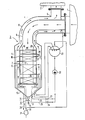
- the figure is a schematic representation of the heat recovery steam generator according to the invention connected to a coal gasifier.
- the figure shows the structure of the heat recovery steam generator 3 connected between a coal gasifier 1 and a gas cleaning system 2.
- the gas supply line 4 coming from the coal gasifier 1 opens from the top downwards and leads centrally in a pressure vessel 5 arranged in the heat exchanger space 6.
- This heat exchanger space is open at the bottom and opens there into the Pressure vessel 5.
- the space between the peripheral walls of the heat exchanger space 6 and the outer wall of the pressure vessel 5 is in turn connected at the upper end of the pressure vessel to a pressure-resistant gas discharge line 8 enclosing the gas supply line 4.
- the bottom 10 of the pressure vessel 5 is funnel-shaped and carries an ash discharge device 11 at its lowest point. This consists of an ash lock 12 with two valves 13, 14 connected in series.
- Your fin tubes are connected in series with those of the surrounding walls 7.
- the heat exchanger tubes of the economizer heating surfaces 18, the evaporator heating surfaces 17 and the fin tubes of the gas supply line 4 are connected on the output side to a common water / steam separation vessel 21.
- the heated water is conveyed via a circulation pump 22 into two strands 25, 26 which can be acted upon independently by means of control valves 23, 24.
- the water is conveyed into the evaporator heating surfaces 17 via one of these two strands 25 and into the fin tubes of the surrounding walls 7 of the heat exchanger space 6 and the support tubes 19, 20 connected in parallel via the other of these two strands 26.
- the water of the circulating line 26 leaving the heat exchanger tubes of the surrounding walls 7 and the support tubes 19, 20 is passed into the heat exchanger tubes of the gas supply line 4.
- the steam side of the water vapor separation vessel 21 is connected to the superheater heating surfaces 15, 16 which are connected in series with one another.
- An injection cooler 28 for regulating the temperature of the live steam leaving the last superheater 15 via the live steam line 29 is installed in the steam line 27 connecting the two superheater heating surfaces.
- a feed water line 30 coming from the condenser (not shown further here) is connected via a feed water pump 31 to the input of the economizer 18.
- the hot, dust-containing raw gas generated there flows via the gas feed line 4 from above into the heat exchanger space 6 of the heat recovery steam generator 3.
- This gas has a temperature of about 1000 to 1400 ° C and due to the leaching of the coal gasifier 1 a pressure of 10 to 60 bar. It is heavily loaded with dust particles. It initially flows through the heat exchanger space 6: the open superheater heating surfaces 15. 16. Then the evaporator heating surfaces 17 and finally the Econemiser heating surfaces 18 in order to flow largely cooled at the lower open end of the heat exchanger space 6 into the pressure vessel 5 and to be deflected by 180 °. Outside cer surrounding walls 7 of the heat exchanger space 6, but within the pressure vessel 5, the cooled raw gas flows up again.
- the dust particles become 10 ces both by the deflection by 180 ° and also by gravity in the ash funnel in the floor Pressure container hurled.
- the ash can be removed there via the ash discharge device 11.
- the gas which has been largely freed of ash and cooled to 150 to 400 ° C., now flows upwards in the pressure vessel 5 and almost back to the coal gasifier 1 via the gas discharge line 8 surrounding the gas supply line 4. Via the branch 9 in the gas exhaust line 8, it flows to the gas cleaning system 2. On this way back, it also cools the gas supply line 4 and supports it with its pressure, so that the gas supply line 4 only the differential pressure between those flowing into the heat recovery steam generator 3 and those leaving it Gas flow must take up.
- Fresh feed water is fed into the economizer heating surfaces 18 through the feed water line 30 via the feed water pump 31.
- the heated feed water leaving the economizer heating surfaces 18 is partly fed into the evaporator heating surfaces 17 via the water / steam separating vessel 21, the circulation pump 22 and from there is fed back into the steam separating vessel 21 with steam.
- Parallel to the evaporator heating surfaces 17, part of the heated feed water is also conveyed into the heat exchanger tubes of the surrounding walls 7 of the heat exchanger chamber 6 and the gas supply line 4.
- the steamed feed water is also conveyed into the water-steam separation vessel 21. There, the feed water separated from the steam is fed back to the circulation pump 22.
- the steam passes from the water vapor separation vessel 21 into the two superheater heating surfaces 15, 16 connected in series. From the second superheater heating surface 15, the steam flows directly via the live steam line 29 to the consumer.
- the quality of the live steam can also be regulated by the injection cooler 28 connected between the two superheater heating surfaces in the steam line.
Landscapes
- Engineering & Computer Science (AREA)
- Physics & Mathematics (AREA)
- Thermal Sciences (AREA)
- Mechanical Engineering (AREA)
- General Engineering & Computer Science (AREA)
- Combustion & Propulsion (AREA)
- Chemical & Material Sciences (AREA)
- Life Sciences & Earth Sciences (AREA)
- Sustainable Development (AREA)
- Sustainable Energy (AREA)
- Heat-Exchange Devices With Radiators And Conduit Assemblies (AREA)
- Chimneys And Flues (AREA)
- Engine Equipment That Uses Special Cycles (AREA)
Applications Claiming Priority (2)
| Application Number | Priority Date | Filing Date | Title |
|---|---|---|---|
| DE19853515174 DE3515174A1 (de) | 1985-04-26 | 1985-04-26 | Abhitzedampferzeuger |
| DE3515174 | 1985-04-26 |
Publications (2)
| Publication Number | Publication Date |
|---|---|
| EP0199251A1 true EP0199251A1 (fr) | 1986-10-29 |
| EP0199251B1 EP0199251B1 (fr) | 1988-06-29 |
Family
ID=6269241
Family Applications (1)
| Application Number | Title | Priority Date | Filing Date |
|---|---|---|---|
| EP86105132A Expired EP0199251B1 (fr) | 1985-04-26 | 1986-04-14 | Générateur de vapeur à chaleur perdue |
Country Status (5)
| Country | Link |
|---|---|
| US (1) | US4738224A (fr) |
| EP (1) | EP0199251B1 (fr) |
| AU (1) | AU583614B2 (fr) |
| DE (2) | DE3515174A1 (fr) |
| IN (1) | IN163199B (fr) |
Cited By (3)
| Publication number | Priority date | Publication date | Assignee | Title |
|---|---|---|---|---|
| WO2001088435A1 (fr) * | 2000-05-19 | 2001-11-22 | Shell Internationale Research Maatschappij B.V. | Processus de chauffage de vapeur |
| US6886501B2 (en) | 2001-05-17 | 2005-05-03 | Shell Oil Company | Apparatus and process for heating steam |
| CN101135432A (zh) * | 2006-09-01 | 2008-03-05 | 巴布考克及威尔考克斯公司 | 用于容纳和冷却合成气体的蒸汽发生器 |
Families Citing this family (11)
| Publication number | Priority date | Publication date | Assignee | Title |
|---|---|---|---|---|
| CA1312292C (fr) * | 1987-04-06 | 1993-01-05 | Daniel Dupuis | Sac filtrant et filtre |
| JP2554101B2 (ja) * | 1987-09-28 | 1996-11-13 | 三菱重工業株式会社 | 排ガスボイラ |
| US5311844A (en) * | 1992-03-27 | 1994-05-17 | Foster Wheeler Energy Corporation | Internested superheater and reheater tube arrangement for heat recovery steam generator |
| JP3017623B2 (ja) * | 1993-09-28 | 2000-03-13 | 株式会社日立製作所 | 石炭ガス化装置 |
| US5921285A (en) * | 1995-09-28 | 1999-07-13 | Fiberspar Spoolable Products, Inc. | Composite spoolable tube |
| DE19651678A1 (de) * | 1996-12-12 | 1998-06-25 | Siemens Ag | Dampferzeuger |
| EP1794495B1 (fr) * | 2004-09-23 | 2017-04-26 | Siemens Aktiengesellschaft | Generateur de vapeur en continu chauffe a l'aide d'un combustible fossile |
| KR100860493B1 (ko) * | 2008-06-09 | 2008-09-26 | 정재억 | 냉각 탈진 장치 |
| DE102013212286B4 (de) * | 2013-06-26 | 2015-07-02 | Lambion Energy Solutions Gmbh | Anlage zur Energierückgewinnung aus heißen Gasen |
| US9429339B2 (en) * | 2014-09-25 | 2016-08-30 | Miclau—S.R.I. Inc. | Domestic gas-fired water heater condensing flue system |
| JP6621310B2 (ja) * | 2015-11-18 | 2019-12-18 | 三菱日立パワーシステムズ株式会社 | ガス化装置、制御装置、ガス化複合発電設備及び制御方法 |
Citations (10)
| Publication number | Priority date | Publication date | Assignee | Title |
|---|---|---|---|---|
| GB349345A (en) * | 1930-06-24 | 1931-05-28 | Howard John Fountain | Improvements in steam generators and water heaters |
| CH200146A (de) * | 1938-02-04 | 1938-09-30 | Buss Ag | Dampfkesselanlage. |
| GB653540A (en) * | 1947-07-02 | 1951-05-16 | Comb Eng Superheater Inc | Improvements in steam boilers and like heat exchangers |
| GB772991A (en) * | 1955-09-07 | 1957-04-17 | La Mont Int Ass Ltd | Improvements in and relating to forced recirculation steam generators |
| US3754533A (en) * | 1971-11-24 | 1973-08-28 | Babcock & Wilcox Ltd | Tube support system |
| GB2068095A (en) * | 1980-01-23 | 1981-08-05 | Combustion Eng | Steam generating heat exchanger |
| EP0048326A2 (fr) * | 1980-09-19 | 1982-03-31 | GebràDer Sulzer Aktiengesellschaft | Refroidisseur de gaz chauds pour une installation de gazéification de charbon |
| FR2522113A1 (fr) * | 1982-02-24 | 1983-08-26 | Steinmueller Gmbh L & C | Chaudiere de recuperation |
| WO1984000411A1 (fr) * | 1982-07-12 | 1984-02-02 | Stork Ketels Mij Tot Expl Van | Reservoir vertical de rayonnement |
| DE3248096C2 (de) * | 1982-12-24 | 1985-01-31 | M.A.N. Maschinenfabrik Augsburg-Nürnberg AG, 4200 Oberhausen | Stehende Vorrichtung zum Kühlen von unter hohem Druck stehenden Gasen mit hohem Staubanteil |
Family Cites Families (5)
| Publication number | Priority date | Publication date | Assignee | Title |
|---|---|---|---|---|
| US2020686A (en) * | 1935-11-12 | Waste heat economizer | ||
| US2547589A (en) * | 1947-07-02 | 1951-04-03 | Comb Eng Superheater Inc | Apparatus for extracting heat from gases under pressure |
| US4286528A (en) * | 1979-08-30 | 1981-09-01 | Stephen Willard | Exhaust filter system |
| CH656637A5 (de) * | 1981-10-26 | 1986-07-15 | Sulzer Ag | Gaskuehler-anordnung zu kohlevergasungsanlage. |
| GB2115129B (en) * | 1982-02-15 | 1984-10-31 | Shell Int Research | Process for the cooling of small particles-containing gases |
-
1985
- 1985-04-26 DE DE19853515174 patent/DE3515174A1/de not_active Withdrawn
-
1986
- 1986-04-11 IN IN286/CAL/86A patent/IN163199B/en unknown
- 1986-04-14 DE DE8686105132T patent/DE3660357D1/de not_active Expired
- 1986-04-14 EP EP86105132A patent/EP0199251B1/fr not_active Expired
- 1986-04-24 US US06/855,753 patent/US4738224A/en not_active Expired - Lifetime
- 1986-04-24 AU AU56597/86A patent/AU583614B2/en not_active Ceased
Patent Citations (10)
| Publication number | Priority date | Publication date | Assignee | Title |
|---|---|---|---|---|
| GB349345A (en) * | 1930-06-24 | 1931-05-28 | Howard John Fountain | Improvements in steam generators and water heaters |
| CH200146A (de) * | 1938-02-04 | 1938-09-30 | Buss Ag | Dampfkesselanlage. |
| GB653540A (en) * | 1947-07-02 | 1951-05-16 | Comb Eng Superheater Inc | Improvements in steam boilers and like heat exchangers |
| GB772991A (en) * | 1955-09-07 | 1957-04-17 | La Mont Int Ass Ltd | Improvements in and relating to forced recirculation steam generators |
| US3754533A (en) * | 1971-11-24 | 1973-08-28 | Babcock & Wilcox Ltd | Tube support system |
| GB2068095A (en) * | 1980-01-23 | 1981-08-05 | Combustion Eng | Steam generating heat exchanger |
| EP0048326A2 (fr) * | 1980-09-19 | 1982-03-31 | GebràDer Sulzer Aktiengesellschaft | Refroidisseur de gaz chauds pour une installation de gazéification de charbon |
| FR2522113A1 (fr) * | 1982-02-24 | 1983-08-26 | Steinmueller Gmbh L & C | Chaudiere de recuperation |
| WO1984000411A1 (fr) * | 1982-07-12 | 1984-02-02 | Stork Ketels Mij Tot Expl Van | Reservoir vertical de rayonnement |
| DE3248096C2 (de) * | 1982-12-24 | 1985-01-31 | M.A.N. Maschinenfabrik Augsburg-Nürnberg AG, 4200 Oberhausen | Stehende Vorrichtung zum Kühlen von unter hohem Druck stehenden Gasen mit hohem Staubanteil |
Cited By (7)
| Publication number | Priority date | Publication date | Assignee | Title |
|---|---|---|---|---|
| WO2001088435A1 (fr) * | 2000-05-19 | 2001-11-22 | Shell Internationale Research Maatschappij B.V. | Processus de chauffage de vapeur |
| WO2001090641A1 (fr) * | 2000-05-19 | 2001-11-29 | Shell Internationale Research Maatschappij B.V. | Appareil permettant de chauffer de la vapeur |
| US6766772B2 (en) | 2000-05-19 | 2004-07-27 | Shell Oil Company | Apparatus for heating steam |
| US6840199B2 (en) | 2000-05-19 | 2005-01-11 | Shell Oil Company | Process for heating system |
| US6886501B2 (en) | 2001-05-17 | 2005-05-03 | Shell Oil Company | Apparatus and process for heating steam |
| CN101135432A (zh) * | 2006-09-01 | 2008-03-05 | 巴布考克及威尔考克斯公司 | 用于容纳和冷却合成气体的蒸汽发生器 |
| CN101135432B (zh) * | 2006-09-01 | 2013-04-24 | 巴布考克及威尔考克斯公司 | 用于容纳和冷却合成气体的蒸汽发生器 |
Also Published As
| Publication number | Publication date |
|---|---|
| EP0199251B1 (fr) | 1988-06-29 |
| IN163199B (fr) | 1988-08-20 |
| US4738224A (en) | 1988-04-19 |
| DE3515174A1 (de) | 1986-11-06 |
| AU583614B2 (en) | 1989-05-04 |
| AU5659786A (en) | 1986-10-30 |
| DE3660357D1 (en) | 1988-08-04 |
Similar Documents
| Publication | Publication Date | Title |
|---|---|---|
| EP0526816B1 (fr) | Centrale à turbines à gaz et à vapeur avec un générateur de vapeur solaire | |
| EP0199251B1 (fr) | Générateur de vapeur à chaleur perdue | |
| EP0425717A1 (fr) | Générateur de vapeur à passage unique | |
| EP0773349A1 (fr) | Refroidisseur d'air de refroidissement pour centrales | |
| DE1051425B (de) | Druckwasserreaktoranlage mit UEberhitzung des Arbeitsmittels | |
| EP0077851A2 (fr) | Appareil refroidisseur de gaz pour une installation de gazéification de charbon | |
| DE19545308A1 (de) | Konvektiver Gegenstromwärmeübertrager | |
| DE1614620B2 (de) | Kernkraftwerk mit co tief 2 - kuehlung | |
| DE2249581A1 (de) | Waermetauscher | |
| EP0224050B1 (fr) | Générateur de vapeur chauffé au charbon pour centrale combinée au charbon | |
| DE1119424B (de) | Dampferzeuger | |
| DE69210619T2 (de) | Temperaturmessung am ausgang eines verdampfers | |
| DE2842039A1 (de) | Dampferzeuger | |
| EP0848208A2 (fr) | Purification du cycle eau-vapeur dans une chaudière à passage unique | |
| DE3446101C2 (fr) | ||
| DE2656463C3 (de) | Kernkraftanlage mit gasgekühltem Reaktor | |
| DE2458382C2 (de) | Speisewasservorwaermer mit zwei dampfraeumen | |
| DE3101051A1 (de) | "zwischenkreislauf fuer ein druckfliessbett" | |
| DE3511877A1 (de) | Durchlaufdampferzeuger | |
| DE2360066C2 (de) | Drucklose Einrichtung zum Kühlen der Abgase von Stahlwerkskonvertern | |
| DE1139215B (de) | Atomkernreaktoranlage | |
| DE1614620C3 (de) | Kernkraftwerk mit CO tief 2 - Kühlung | |
| DE6606786U (de) | Waermetauscher. | |
| DE1969151U (de) | Dampferzeuger fuer kernkraftwerke. | |
| DE1551005C (de) | Überkritischer Zwanglaufdampfer ?euger |
Legal Events
| Date | Code | Title | Description |
|---|---|---|---|
| PUAI | Public reference made under article 153(3) epc to a published international application that has entered the european phase |
Free format text: ORIGINAL CODE: 0009012 |
|
| AK | Designated contracting states |
Kind code of ref document: A1 Designated state(s): DE GB |
|
| 17P | Request for examination filed |
Effective date: 19861203 |
|
| 17Q | First examination report despatched |
Effective date: 19870507 |
|
| RAP1 | Party data changed (applicant data changed or rights of an application transferred) |
Owner name: SIEMENS AKTIENGESELLSCHAFT BERLIN UND MUENCHEN |
|
| GRAA | (expected) grant |
Free format text: ORIGINAL CODE: 0009210 |
|
| AK | Designated contracting states |
Kind code of ref document: B1 Designated state(s): DE GB |
|
| REF | Corresponds to: |
Ref document number: 3660357 Country of ref document: DE Date of ref document: 19880804 |
|
| GBT | Gb: translation of ep patent filed (gb section 77(6)(a)/1977) | ||
| PLBE | No opposition filed within time limit |
Free format text: ORIGINAL CODE: 0009261 |
|
| STAA | Information on the status of an ep patent application or granted ep patent |
Free format text: STATUS: NO OPPOSITION FILED WITHIN TIME LIMIT |
|
| 26N | No opposition filed | ||
| PGFP | Annual fee paid to national office [announced via postgrant information from national office to epo] |
Ref country code: DE Payment date: 20000619 Year of fee payment: 15 |
|
| PGFP | Annual fee paid to national office [announced via postgrant information from national office to epo] |
Ref country code: GB Payment date: 20010409 Year of fee payment: 16 |
|
| REG | Reference to a national code |
Ref country code: GB Ref legal event code: IF02 |
|
| PG25 | Lapsed in a contracting state [announced via postgrant information from national office to epo] |
Ref country code: DE Free format text: LAPSE BECAUSE OF NON-PAYMENT OF DUE FEES Effective date: 20020201 |
|
| PG25 | Lapsed in a contracting state [announced via postgrant information from national office to epo] |
Ref country code: GB Free format text: LAPSE BECAUSE OF NON-PAYMENT OF DUE FEES Effective date: 20020414 |
|
| GBPC | Gb: european patent ceased through non-payment of renewal fee |
Effective date: 20020414 |