EP0199265A2 - Zahnradanordnung ohne Spiel im Eingriff mit einem dritten Zahnrad - Google Patents
Zahnradanordnung ohne Spiel im Eingriff mit einem dritten Zahnrad Download PDFInfo
- Publication number
- EP0199265A2 EP0199265A2 EP86105198A EP86105198A EP0199265A2 EP 0199265 A2 EP0199265 A2 EP 0199265A2 EP 86105198 A EP86105198 A EP 86105198A EP 86105198 A EP86105198 A EP 86105198A EP 0199265 A2 EP0199265 A2 EP 0199265A2
- Authority
- EP
- European Patent Office
- Prior art keywords
- gear
- spring
- gears
- pin
- spring means
- Prior art date
- Legal status (The legal status is an assumption and is not a legal conclusion. Google has not performed a legal analysis and makes no representation as to the accuracy of the status listed.)
- Granted
Links
Images


Classifications
-
- F—MECHANICAL ENGINEERING; LIGHTING; HEATING; WEAPONS; BLASTING
- F16—ENGINEERING ELEMENTS AND UNITS; GENERAL MEASURES FOR PRODUCING AND MAINTAINING EFFECTIVE FUNCTIONING OF MACHINES OR INSTALLATIONS; THERMAL INSULATION IN GENERAL
- F16H—GEARING
- F16H55/00—Elements with teeth or friction surfaces for conveying motion; Worms, pulleys or sheaves for gearing mechanisms
- F16H55/02—Toothed members; Worms
- F16H55/17—Toothed wheels
- F16H55/18—Special devices for taking up backlash
-
- Y—GENERAL TAGGING OF NEW TECHNOLOGICAL DEVELOPMENTS; GENERAL TAGGING OF CROSS-SECTIONAL TECHNOLOGIES SPANNING OVER SEVERAL SECTIONS OF THE IPC; TECHNICAL SUBJECTS COVERED BY FORMER USPC CROSS-REFERENCE ART COLLECTIONS [XRACs] AND DIGESTS
- Y10—TECHNICAL SUBJECTS COVERED BY FORMER USPC
- Y10T—TECHNICAL SUBJECTS COVERED BY FORMER US CLASSIFICATION
- Y10T74/00—Machine element or mechanism
- Y10T74/19—Gearing
- Y10T74/19623—Backlash take-up
-
- Y—GENERAL TAGGING OF NEW TECHNOLOGICAL DEVELOPMENTS; GENERAL TAGGING OF CROSS-SECTIONAL TECHNOLOGIES SPANNING OVER SEVERAL SECTIONS OF THE IPC; TECHNICAL SUBJECTS COVERED BY FORMER USPC CROSS-REFERENCE ART COLLECTIONS [XRACs] AND DIGESTS
- Y10—TECHNICAL SUBJECTS COVERED BY FORMER USPC
- Y10T—TECHNICAL SUBJECTS COVERED BY FORMER US CLASSIFICATION
- Y10T74/00—Machine element or mechanism
- Y10T74/19—Gearing
- Y10T74/1987—Rotary bodies
- Y10T74/19893—Sectional
- Y10T74/19898—Backlash take-up
Definitions
- This invention relates to a gear assembly constituted by a single gear to be mated with a third gear in such a manner that backlash therebetween is eliminated, to reduce noise caused by such a mating.
- the present invention can be widely applied in various mechanical fields.
- a conventional non-backlash gear assembly in which the assembly comprises two gears having an identical gear tooth number and profile and a spring anchored at each end to the respective gears, to provide a circumferential biasing force that will tend to rotate the two gears in opposite directions, so that this gear assembly can be mated with a third gear in a nonbacklash manner.
- a compression coil spring is used in the device shown in Fig. 2 of Japanese Examined Utility Model Publication (Kokoku) No. 48-34438 and in Fig. 1 of Japanese Unexamined Utility Model Publication (Kokai) No. 55-158349
- a torsional coil spring is used in Japanese Unexamined Utility Model Publication (Kokai) No. 56-160351
- a C-shaped round steel spring is used in Fig. 1 of Japanese Examined Utility Model Publication (Kokoku) No. 48-34438 and in Fig.
- a snap spring in the form of C-shaped clip is also known.
- the present invention is directed to a gear assembly having this type of C-shaped clip snap spring.
- a known non-backlash gear assembly including a spring in the form of a C-shaped clip, two circular holes are provided in the spring adjacent to either end thereof and each of the two gears has one pin.
- each end of the spring can be connected to each gear by the pin and circular hole.
- This known type of gear assembly has a disadvantage in that the assembly operation is very difficult. Namely, it is very cumbersome to fit the holes to the pins.
- the spring In the first step the spring is rested on the first gear, and the circular hole of one end of the spring is fitted to the pin on the first gear. This is very easy since both the first gear and the spring can be seen by the operator.
- the second step however, the second gear must be moved onto the first gear, to fit the pin on the second gear into the other hole of the spring. This is very cumbersome since the first gear, the spring and the other pin of the second gear cannot be seen because they are blocked by the second gear, and the operator must fit the other hole to the other pin by touch.
- an improved gear assembly has been proposed in Japanese Unexamined Utility Model Publication (Kokai) No. 61-1770 in which the pins are provided on one of the gears, for example, on the first gear, so that the C-shaped clip spring can be easily positioned and held on the first gear by inserting the pins into the respective holes of the spring.
- One of the holes is an elongated hole having a diameter larger than the pins, so that the spring can deform when an external force is applied thereto.
- On the other gear for example, on the second gear, a C-shaped groove is provided corresponding to the C-shaped spring, to receive the spring in the groove.
- the spring can be automatically fitted in the groove of the second gear when the second gear is located on the first gear, so that one of terminal ends of the groove bears against the corresponding terminal end of the spring which is displaceable in the groove, resulting in the production of an elastic biasing force due to the presence of the spring between the gears.
- the elastic connection between the two gears is dependent on the spring force of the C-shaped clip spring alone. Therefore, in order to obtain a sufficient spring force, it is necessary to increase the thickness of the C-shaped clip spring, since the plane size of the C-shaped clip spring is limited by the size of the gears.
- the thickness of the C-shaped spring is increased, it becomes very difficult to form the pin holes on the ends of the C-shaped spring by punching. Namely, the pin holes must be machined by drilling or other mechanical piercing. It is apparent that drilling takes more time than punching, since drilling must be effected for each individual spring, whereas punching can form pin holes in several C-shaped springs substantially at one time.
- drilling tends to produce burrs at the edges of the pin holes or tends to produce eccentric pin holes lacking a high precision. This results in a decrease in the surface contact area between the pin holes and the associated pins inserted therein, resulting in an increase in surface pressure therebetween. The increased surface pressure increases frictional wear of the contacting portions between the pins and pin holes.
- the primary object of the present invention is to provide a simple gear assembly of two gears and a C-shaped spring, which assembly can be easily manufactured and assembled by using a knockout pin instead of the conventional C-shaped groove.
- Another object of the present invention is to provide a gear assembly having a plurality of identical C-shaped springs which contribute to an increase of the elastic biasing force between the two gears.
- a gear assembly adapted for mating with a third gear in a non-backlash manner, the assembly comprising: first and second gears that are coaxially and relatively rotatable, the gears having the same number of teeth, with identical tooth profiles, on the peripheries thereof and having opposing inner surfaces.
- One of the gears is provided with two fixed pins standing on the inner surface thereof, and the other gear is provided with a knockout pin standing on the inner surface thereof.
- a spring is placed between the two gears to connect them with a circumferential spring bias, the spring having at least three pin holes corresponding to the fixed pins and the knockout pin on the first and second gears, at least one of the pin holes corresponding to one of the two fixed pins on one of the gears, the pinhole having a dimension, taken circumferentially of the assembly, greater than the diameter of the associated pin, so that the spring can be elastically deformed by the-application of a force thereto.
- the spring is carried by one of the gears in a prestressed state caused by the mating of the pins on one gear with the corresponding holes of the spring.
- the hole corresponding to the knockout pin on the other gear has a dimension, taken circumferentially of the assembly, greater than the diameter of the knockout pin, and the knockout pin abuts against one end of the knockout pin hole to cause an elastic deformation of the spring.
- the first and second gears together being adapted to mate with a common third gear under the elastic deformation of the spring to provide a non-backlash mating with the third gear.
- the spring comprises a single C-shaped spring.
- the spring comprises a plurality of identical springs, placed one upon the other, each spring having a C-shape.
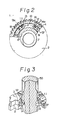
- a non-backlash gear assembly according to the present-invention is generally indicated by the reference numeral 1.
- This assembly 1 comprises a first main gear 2, a second subgear 3, and a spring 4 in the form of a C-shaped clip.
- the gear assembly 1 as a whole constitutes a single gear means which can be mated with a third gear 30, as shown in Fig. 7.
- the first gear 2 and the second gear 3 have conventional teeth 5 and 6 on their peripheries, respectively.
- the tooth profile and the number of the teeth 5 and 6 of each gear 2 and 3 are identical.
- the spring 4 has a shape such as is used for a known retaining-ring or snap ring, and comprises a flat and generally circular arcuate shape.
- the first gear 2 has a cylindrical boss 7 at the central region thereof, to fit the first gear 2 onto a desired shaft (e.g., camshaft 50 in Fig. 3).
- the boss 7 projects coaxially from the first gear 2, the center bore 8 of the second gear 3 being slidably fittable onto the external peripheral surface of the boss 7.
- the first gear 2 and the second gear 3 can be arranged so as to be coaxially and relatively rotatable.
- An annular groove 9 is provided near the free end of the boss 7 for receiving a snap ring (not shown) to retain the second gear 3 on the first gear 2 in the axial direction.
- the first gear 2 has a recessed inner surface 16 on the side from which the boss 7 projects and the second gear 3 has a recessed inner surface 10, these surfaces 10 and 16 opposing each other when the second gear 3 is fitted to the boss 7 of the first gear 2.
- the spring '4 in the form of a C-shaped clip has holes 13 and 14 adjacent to either end thereof.
- the spring 4 can be carried by or rested on the second gear 3 in a prestressed state, namely, in an expanded condition relative to its free initial configuration, with the pins 11 and 12 engaged with the holes 13 and 14 of the spring 4.
- the spring 4 and the pins 11 and 12 are designed in such a manner that the spring 4 is substantially concentrically arranged around the boss 7, as clearly shown in Fig. 2.
- the holes 13 and 14 are elongated holes, the longer side of which extends circumferentially of the spring 4, i.e., circumferentially of the assembly.
- one of the holes 13 and 14 can be a circular hole, the diameter of which substantially conforms to the pin 12. Accordingly, the pins 11 and 12 can abut against the circumferentially inner wall ends 13a and 14a of the corresponding holes 13 and 14, as shown in Figs. 2 and 3, when an external force is not applied to the assembly after the spring 4 is mounted on the second gear 3.
- the spring 4 elastically deforms within the limit determined by a difference in dimension between the hole 13 and the pin 11.
- the spring 4 is fixed at the other end by engaging the pin 12 with the hole 14, such elastic deformation of the spring 4 provides a reaction force to that external force.
- the hole 14 can be a circle into which the pin 12 can be snugly inserted, since the hole 14 is considered to be a fixed end in the illustrated embodiment. If the hole 13 is considered to be the fixed end, the hole 13 can be a circle into which the pin 11 can be snugly fitted. It will be clear from the above description that this reaction force will allow the assembly to mate with the third gear 10 in a non-backlash manner.
- the main gear 2 has a knockout pin 17 on the recessed surface 16.
- the spring 4 has a third hole (knockout pin hole) 18 corresponding to the knockout pin 17.
- a third hole (knockout pin hole) 18 is also provided in the spring 4 in a symmetrical arrangement with the first mentioned third hole 18. This is to ensure that the spring can be assembled on the second gear 3 even if the spring is put in upside down. ⁇ amely, the provision of the two third holes 18 and 19 in a symmetrical arrangement enables the spring to be assembled regardless of which side thereof is up or down. Since the third hole 19 is provided only for convenience in assembly, as mentioned above, it is not essential.
- the pin 17 is adapted to connect the two gears 2 and 3 through the spring 4 when the gears 2 and 3 are superimposed on each other. Namely, the main or first gear 2 is connected to the sub or second gear 3 through the pin 17, the hole - 18 (or 19), the spring 4, the hole 14, and the pin 12.
- the hole 18 (or 19) has a larger inner diameter than the diameter of the knockout pin 17.
- the gear assembly of the present invention can be assembled as follows.
- the main gear 2 is attached to the camshaft 50.
- the spring 4 is attached to the second gear 3 by engaging the pins 11 and 12 of the second gear in the corresponding holes 13 and 14 of the spring 4. That is, when the pins 11 and 12 are inserted in the associated elongated holes 13 and 14 of the spring 4, the spring is expanded in a prestressed state, so that a gap between the opposite ends of the spring 4 is enlarged, as mentioned above. This provides the scissors force of a so-called scissors, gear.
- the second gear 3 on which the spring 4 is provisionally attached is put on the first (main) gear 2 in such a way that the knockout pin 17 of the first gear 2 is inserted in the hole 18 of the spring 4.
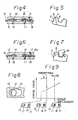
- The" insertion of the knockout pin 17 in the hole 18 is shown in Fig. 4, in which the knockout pin 17 is free in the hole 18, since the hole 18 is slightly larger than the pin 17.
- Figure -5" shows a gear teeth relationship between the main and second gears 2 and 3 when connected to each other in the position shown in Fig. 4.
- the main gear 2 is free from the C-shaped spring 4 within a predetermined amount of play, in Fig. 4, in which the scissors gear of the present invention is not yet meshed with the third gear 30.
- This play namely the play between the pin 17 and the hole 18 is less than the distance between the adjacent teeth 5 or 6 of the first or second gear 2 or 3.
- each tooth of the second gear 3 is superimposed on each tooth of the first gear 2 with a slight displacement therebetween and a gap is present between adjacent sets of the superimposed teeth, as shown in Fig. 5.
- each tooth of the third gear 30 can be forced into that gap between the adjacent sets of the superimposed teeth of the gear assembly, with the result that the teeth of the third gear 30 push the teeth 6 of the second gear 3 in the counterclockwise direction, as shown in Fig. 7, causing the end 18a of the hole 18 of the- spring 4 to push against the pin 17 of the first gear 2.
- the spring 4 then elastically deforms and the end wall 13a of .the hole 13 is released from the pin 11, as shown in Fig. 6.
- the spring 4 therefore, effects a reaction force to the second gear 3, as indicated by the arrow F.
- the teeth 6 of the second gear 3 are always in contact with the teeth of the third gear 30, so that each tooth of the third gear 30 is clamped between each tooth 5 of the first gear 2 and each tooth 6 of the second gear 3, even when backlash is provided between the first gear 2 and the third gear 30.
- non-backlash mating is accomplished and noise is reduced.
- the gear assembly i.e., the scissors gear, having the main gear and the second gear, which have teeth slightly separated from the teeth of the main gear by an elastic force
- the scissors gear which has been in a preset position (a provisional position) in which a spring force, i.e., a scissors force, is not produced, comes to a use position in which the necessary scissors force, i.e., the spring biasing force, is produced.
- the amount of play between the reset position and the use position depends on the shift or deviation between the teeth of the first and the second gears at the preset position.
- the amount of play must be small in view of the gear teeth of the third gear 30 to be meshed therewith. However, if there is a small amount of play, and the pin 12 (or 17) becomes worn, as shown at 12' in Fig. 8, a slight displacement of the contact point between the pin 12 (or 17) and the hole 14 (or 18) will result and the amount of play is easily reduced to zero.
- This loss of play causes the presetting pin 11 to come into contact with the end wall of the elongated hole 13, so that the spring force of the spring 4 is received by the pin 11. This means a loss of spring bias, and accordingly, a loss of the scissors function of the gear assembly of the present invention.
- the pins 12 and 17, which receive the load when the gears are in use are preferably made of a high wear-resistance or abrasion resistance material or are subject to a wear or abrasion resistance surface treatment.
- the pin 11 can be made of a material which has only a relatively small resistance to the dead or static load acting thereon in presetting and which can be easily worn in use. This is because the pin 11 is useful only in the presetting stage, as will be apparent from Fig. 6 and it can be dispensed with when the gear assembly is actually mated with the third gear.
- the pin 11 is made of a material which tends to be easily worn as mentioned above, even when the pin 12 or 17 is worn and would otherwise cause a deterioration of the scissors function of the gears, the scissors function can be still maintained because the pin 11 will be worn to a larger extent than the pin 12 or 17, as can be seen in Fig. 9.
- the worn pins 11 are designated by 11' and 11", of which 11' suffice the most wear.
- the use of a wearable pin 11 can provide a wear allowance S.
- the material of which the pin 11 is made can be, for example, a metal that has not been subjected to a surface treatment, such as Al, Cu, copper alloy, or it can be made of a plastic or resin material.
- the pins 11 and 12, and the corresponding holes 13 and 14 have different diameters to enable the pins and the holes to be easily distinguished from one another, and thus prevent an incorrect assembly.
- a plurality of identical C-shaped clip springs 4 are provided.
- two springs 4 are provided but the number of springs is not limited and may be more than two. These springs 4 are aligned and located one upon the other.
- the spring force of the two springs 4 corresponds to that of the single spring 4 of Fig. 1.
- the spring force of the combined springs 4 in Fig. 10 will be twice that of the spring force of the spring 4 in Fig. 1.
- the increased number of springs 4 increases the spring force of the spring 4 as a whole.
- the thickness of each spring 4 in the increased number of springs is decreased, the same-spring force can be produced in total.
- the decrease in thickness of one spring 4 enables the holes 13, 14, 18 and 19 of the spring 4 to be formed by a punching press.
- the holes of the spring must be formed by drilling or the like.
- the pins 11 and 13 can be provided on the first gear and the knockout pin 17 can be provided on the second gear, contrary to the illustrated arrangement.
- the hole means can include means for engaging or securing the spring with the pin, such as a hole partly encircled by a hook.
- the connection between the main gear and the subgear can be effected by the knockout pin provided on one of the two gears, resulting in an easy production and assembly of the scissors gear.
- the spring can be provisionally attached to the sub gear (or main gear), the subassembly which has the subgear and the spring attached in advance thereto can be easily assembled with the main gear (or subgear) which has been already attached to the cam shaft.
- a number of subassemblies can be prepared in advance for use on an assembly line, if necessary.
- the thickness of one spring can be decreased.
- the increased number of springs also contributes to an increase in the total effective contact surface area between the pins and the associated pin holes, resulting in a decrease in the surface pressure thereat.
- the provision of a plurality of springs ensures that any possible differences in spring force between the springs can be cancelled or effectively absorbed.
Landscapes
- Engineering & Computer Science (AREA)
- General Engineering & Computer Science (AREA)
- Mechanical Engineering (AREA)
- Gears, Cams (AREA)
Applications Claiming Priority (4)
| Application Number | Priority Date | Filing Date | Title |
|---|---|---|---|
| JP5955985U JPH0343490Y2 (de) | 1985-04-23 | 1985-04-23 | |
| JP59559/85U | 1985-04-23 | ||
| JP59558/85U | 1985-04-23 | ||
| JP1985059558U JPH0413465Y2 (de) | 1985-04-23 | 1985-04-23 |
Publications (3)
| Publication Number | Publication Date |
|---|---|
| EP0199265A2 true EP0199265A2 (de) | 1986-10-29 |
| EP0199265A3 EP0199265A3 (en) | 1986-12-10 |
| EP0199265B1 EP0199265B1 (de) | 1989-03-22 |
Family
ID=26400605
Family Applications (1)
| Application Number | Title | Priority Date | Filing Date |
|---|---|---|---|
| EP86105198A Expired EP0199265B1 (de) | 1985-04-23 | 1986-04-15 | Zahnradanordnung ohne Spiel im Eingriff mit einem dritten Zahnrad |
Country Status (3)
| Country | Link |
|---|---|
| US (1) | US4688441A (de) |
| EP (1) | EP0199265B1 (de) |
| DE (1) | DE3662555D1 (de) |
Cited By (3)
| Publication number | Priority date | Publication date | Assignee | Title |
|---|---|---|---|---|
| WO1989010504A1 (en) * | 1988-04-26 | 1989-11-02 | Ab Volvo | Device for eliminating rattle in a gear box |
| GB2282204A (en) * | 1993-07-14 | 1995-03-29 | Geodetic Machines Ltd | Antibacklash gearing arrangement |
| WO1995012077A1 (de) * | 1993-10-27 | 1995-05-04 | Gruner + Jahr Ag & Co. | Periodisch übersetzendes getriebe mit unrunden zahnrädern |
Families Citing this family (23)
| Publication number | Priority date | Publication date | Assignee | Title |
|---|---|---|---|---|
| JPH0613596Y2 (ja) * | 1987-07-07 | 1994-04-06 | 本田技研工業株式会社 | エンジンへの発電機支持装置 |
| US4920828A (en) * | 1988-02-08 | 1990-05-01 | Mazda Motor Corporation | Planetary gear type transmission |
| US5189720A (en) * | 1989-04-03 | 1993-02-23 | Sumitomo Electric Industries, Ltd. | Method for manufacturing steel wire material for reinforcing optical fiber |
| US5056613A (en) * | 1990-07-27 | 1991-10-15 | Ford Motor Company | Vehicular speed control system with reduced gear chatter |
| US5725035A (en) * | 1996-06-05 | 1998-03-10 | Black & Decker Inc. | Apparatus for adjusting the relative positions of two components of a power tool |
| US20040089089A1 (en) * | 2002-11-08 | 2004-05-13 | Stevens Carlos J. | Anti-backlash method and system for multiple mesh gear train |
| GB2411937A (en) * | 2004-03-11 | 2005-09-14 | Autoliv Dev | Anti-backlash mechanism for the gear of a steering wheel |
| US20050209033A1 (en) * | 2004-03-19 | 2005-09-22 | Borgwarner Inc. | Spline phased multiple sprocket |
| US20090095103A1 (en) * | 2007-10-11 | 2009-04-16 | Thomas Duzzie | Two-part gearwheel |
| US7533639B1 (en) * | 2007-10-29 | 2009-05-19 | Ford Global Technologies, Llc | Dual crankshaft engine with counter rotating inertial masses |
| DE102008050471A1 (de) * | 2008-10-04 | 2010-04-08 | Thyssenkrupp Presta Teccenter Ag | Geteiltes Zahnrad |
| DE102008050472B4 (de) * | 2008-10-04 | 2012-06-06 | Thyssenkrupp Presta Teccenter Ag | Geteiltes Zahnrad |
| KR101047607B1 (ko) * | 2008-12-05 | 2011-07-07 | 현대자동차주식회사 | 시저스 기어 |
| AT508701B1 (de) * | 2010-06-23 | 2011-05-15 | Miba Sinter Austria Gmbh | Zahnradanordnung |
| KR101360422B1 (ko) * | 2011-12-08 | 2014-02-11 | 기아자동차주식회사 | 시저스기어 구조 및 그 제조방법 |
| DE102012025210B4 (de) * | 2012-12-28 | 2014-08-14 | Gkn Sinter Metals Holding Gmbh | Geteiltes Zahnrad |
| DE102013012953A1 (de) * | 2013-08-02 | 2014-07-24 | Daimler Ag | Stirnradtrieb für einen Ventiltrieb einer Brennkraftmaschine |
| NL2012082C2 (en) * | 2014-01-14 | 2015-07-16 | Vcst Ind Products Bvba | Scissor gear assembly. |
| DE102014208269B3 (de) * | 2014-04-30 | 2015-09-03 | Magna Powertrain Ag & Co. Kg | Verfahren zur Herstellung einer spielfreien Getriebestufe |
| DE102014223505A1 (de) * | 2014-11-18 | 2016-05-19 | Zf Friedrichshafen Ag | Welle-Nabe-Verbindung eines Doppelzahnrades auf einer Getriebewelle |
| DE102017126205A1 (de) * | 2017-11-09 | 2019-05-09 | Man Truck & Bus Ag | Zahnrad, insbesondere Zwischenrad, für einen Rädertrieb |
| USD902252S1 (en) * | 2018-06-04 | 2020-11-17 | Transportation IP Holdings, LLP | Modular cam shaft |
| DE102018220836A1 (de) * | 2018-12-03 | 2020-06-04 | Zf Friedrichshafen Ag | Geteiltes Zahnrad mit mehreren in Umfangsrichtung verspannbaren Zahnradteilen |
Family Cites Families (13)
| Publication number | Priority date | Publication date | Assignee | Title |
|---|---|---|---|---|
| US1746178A (en) * | 1927-12-17 | 1930-02-04 | Alexander M Alexandrescu | Gear |
| US2663198A (en) * | 1952-10-15 | 1953-12-22 | Bendix Aviat Corp | Antibacklash gearing |
| GB792330A (en) * | 1955-11-23 | 1958-03-26 | Caterpillar Tractor Co | Resilient gear |
| US2966806A (en) * | 1958-07-28 | 1961-01-03 | Alfred O Luning | Antibacklash gears |
| US2902879A (en) * | 1958-10-03 | 1959-09-08 | Bell Telephone Labor Inc | Anti-backlash gear assembly |
| US3135152A (en) * | 1963-03-18 | 1964-06-02 | William H Bedinghaus | Rotary perforating roll units supported for movement towards and away from each other |
| DE1625596A1 (de) * | 1967-07-27 | 1970-07-16 | Philips Patentverwaltung | Vorrichtung zum gegenseitigen Verspannen zweier Zahnraeder |
| JPS534773B2 (de) * | 1971-09-07 | 1978-02-21 | ||
| JPS55158349A (en) * | 1979-05-30 | 1980-12-09 | Unitika Ltd | Production of blended fiber filament |
| JPS56160351A (en) * | 1980-05-10 | 1981-12-10 | Fukubi Kagaku Kogyo Kk | Good extrusion formability cement admixture with alkali-resistant glass fiber |
| JPS60161083A (ja) * | 1984-01-30 | 1985-08-22 | 三菱電機株式会社 | ア−ク溶接ロボツトの旋回軸バツクラツシユ補正装置 |
| JPS611770A (ja) * | 1984-06-12 | 1986-01-07 | 日精株式会社 | 垂直循環式駐車装置 |
| JPS611770U (ja) * | 1984-06-12 | 1986-01-08 | トヨタ自動車株式会社 | 無背隙歯車装置 |
-
1986
- 1986-04-04 US US06/848,307 patent/US4688441A/en not_active Expired - Fee Related
- 1986-04-15 DE DE8686105198T patent/DE3662555D1/de not_active Expired
- 1986-04-15 EP EP86105198A patent/EP0199265B1/de not_active Expired
Cited By (5)
| Publication number | Priority date | Publication date | Assignee | Title |
|---|---|---|---|---|
| WO1989010504A1 (en) * | 1988-04-26 | 1989-11-02 | Ab Volvo | Device for eliminating rattle in a gear box |
| US5067364A (en) * | 1988-04-26 | 1991-11-26 | Ab Volvo | Device for eliminating rattle in a gear box |
| GB2282204A (en) * | 1993-07-14 | 1995-03-29 | Geodetic Machines Ltd | Antibacklash gearing arrangement |
| GB2282204B (en) * | 1993-07-14 | 1997-07-02 | Geodetic Machines Ltd | Improvements relating to antibacklash gearing |
| WO1995012077A1 (de) * | 1993-10-27 | 1995-05-04 | Gruner + Jahr Ag & Co. | Periodisch übersetzendes getriebe mit unrunden zahnrädern |
Also Published As
| Publication number | Publication date |
|---|---|
| EP0199265A3 (en) | 1986-12-10 |
| EP0199265B1 (de) | 1989-03-22 |
| DE3662555D1 (en) | 1989-04-27 |
| US4688441A (en) | 1987-08-25 |
Similar Documents
| Publication | Publication Date | Title |
|---|---|---|
| US4688441A (en) | Gear assembly for mating with third gear without backlash | |
| US4745823A (en) | Gear assembly adapted for mating with a third gear without backlash | |
| US4640147A (en) | Gear assembly adapted for mating with a third gear without backlash | |
| US4854764A (en) | Coupling device between two elements | |
| US6098394A (en) | Band-like accessory | |
| US5106329A (en) | Socket contact | |
| EP0663980B1 (de) | Reibungsscharnier | |
| US4820184A (en) | Electrical connector retaining ratchet | |
| JPS63282709A (ja) | 光コネクタのプラグ | |
| IL95452A (en) | Seamless bimetallic disc, especially for coins and the like | |
| US6113306A (en) | Securing ring ("c" clip) | |
| JP2806936B2 (ja) | 機械的な倍力装置 | |
| US4846764A (en) | Constant velocity joint cage and method for making same | |
| US5660484A (en) | Shaft with bearing assembly | |
| EP1597489A1 (de) | Kardangelenk mit haltemechanismus | |
| US4770546A (en) | Tension bush | |
| EP1106096A2 (de) | Verbindungselement für Uhr und Armband | |
| EP0382955A1 (de) | Rollenkupplung | |
| US20030217475A1 (en) | Radially relieved locating pin | |
| JP2003189914A (ja) | 帯状装身具 | |
| JPH0413465Y2 (de) | ||
| JPS60157509A (ja) | ピストン及び連接棒組立体用ヨ−クスラストベアリング及びその組立方法 | |
| US6514004B2 (en) | Connecting structure for pieces of a strap made of hard materials | |
| CN115958548B (zh) | 扭力结构 | |
| JPH0343490Y2 (de) |
Legal Events
| Date | Code | Title | Description |
|---|---|---|---|
| PUAI | Public reference made under article 153(3) epc to a published international application that has entered the european phase |
Free format text: ORIGINAL CODE: 0009012 |
|
| PUAL | Search report despatched |
Free format text: ORIGINAL CODE: 0009013 |
|
| 17P | Request for examination filed |
Effective date: 19860415 |
|
| AK | Designated contracting states |
Kind code of ref document: A2 Designated state(s): DE FR |
|
| AK | Designated contracting states |
Kind code of ref document: A3 Designated state(s): DE FR |
|
| 17Q | First examination report despatched |
Effective date: 19880129 |
|
| GRAA | (expected) grant |
Free format text: ORIGINAL CODE: 0009210 |
|
| AK | Designated contracting states |
Kind code of ref document: B1 Designated state(s): DE FR |
|
| REF | Corresponds to: |
Ref document number: 3662555 Country of ref document: DE Date of ref document: 19890427 |
|
| ET | Fr: translation filed | ||
| PLBE | No opposition filed within time limit |
Free format text: ORIGINAL CODE: 0009261 |
|
| STAA | Information on the status of an ep patent application or granted ep patent |
Free format text: STATUS: NO OPPOSITION FILED WITHIN TIME LIMIT |
|
| 26N | No opposition filed | ||
| PGFP | Annual fee paid to national office [announced via postgrant information from national office to epo] |
Ref country code: DE Payment date: 19940408 Year of fee payment: 9 |
|
| PGFP | Annual fee paid to national office [announced via postgrant information from national office to epo] |
Ref country code: FR Payment date: 19940411 Year of fee payment: 9 |
|
| PG25 | Lapsed in a contracting state [announced via postgrant information from national office to epo] |
Ref country code: FR Effective date: 19951229 |
|
| PG25 | Lapsed in a contracting state [announced via postgrant information from national office to epo] |
Ref country code: DE Effective date: 19960103 |
|
| REG | Reference to a national code |
Ref country code: FR Ref legal event code: ST |