EP0199455A2 - Introduction d'un échantillon de plasma dans une chambre à vide - Google Patents
Introduction d'un échantillon de plasma dans une chambre à vide Download PDFInfo
- Publication number
- EP0199455A2 EP0199455A2 EP86301974A EP86301974A EP0199455A2 EP 0199455 A2 EP0199455 A2 EP 0199455A2 EP 86301974 A EP86301974 A EP 86301974A EP 86301974 A EP86301974 A EP 86301974A EP 0199455 A2 EP0199455 A2 EP 0199455A2
- Authority
- EP
- European Patent Office
- Prior art keywords
- orifice
- plasma
- vacuum chamber
- voltage
- plate
- Prior art date
- Legal status (The legal status is an assumption and is not a legal conclusion. Google has not performed a legal analysis and makes no representation as to the accuracy of the status listed.)
- Granted
Links
- 238000005070 sampling Methods 0.000 title claims description 13
- 150000002500 ions Chemical class 0.000 claims abstract description 55
- 230000005540 biological transmission Effects 0.000 claims abstract description 23
- 230000006698 induction Effects 0.000 claims abstract description 7
- 238000000034 method Methods 0.000 claims description 10
- 238000010438 heat treatment Methods 0.000 claims description 7
- 238000004458 analytical method Methods 0.000 abstract description 5
- 230000001419 dependent effect Effects 0.000 abstract 1
- 230000010363 phase shift Effects 0.000 description 9
- 230000000694 effects Effects 0.000 description 5
- 238000002474 experimental method Methods 0.000 description 5
- 239000007789 gas Substances 0.000 description 5
- XKRFYHLGVUSROY-UHFFFAOYSA-N Argon Chemical compound [Ar] XKRFYHLGVUSROY-UHFFFAOYSA-N 0.000 description 4
- 238000010884 ion-beam technique Methods 0.000 description 4
- 239000000126 substance Substances 0.000 description 4
- 239000012159 carrier gas Substances 0.000 description 3
- 230000003321 amplification Effects 0.000 description 2
- 229910052786 argon Inorganic materials 0.000 description 2
- 230000015556 catabolic process Effects 0.000 description 2
- 230000003247 decreasing effect Effects 0.000 description 2
- 239000003574 free electron Substances 0.000 description 2
- 239000000463 material Substances 0.000 description 2
- 238000003199 nucleic acid amplification method Methods 0.000 description 2
- 238000001228 spectrum Methods 0.000 description 2
- 230000002547 anomalous effect Effects 0.000 description 1
- 230000015572 biosynthetic process Effects 0.000 description 1
- 230000002939 deleterious effect Effects 0.000 description 1
- 230000003628 erosive effect Effects 0.000 description 1
- 238000000605 extraction Methods 0.000 description 1
- 230000007246 mechanism Effects 0.000 description 1
- 230000001151 other effect Effects 0.000 description 1
- 230000008054 signal transmission Effects 0.000 description 1
- 238000004544 sputter deposition Methods 0.000 description 1
- 239000013589 supplement Substances 0.000 description 1
- 238000011144 upstream manufacturing Methods 0.000 description 1
- 229910052720 vanadium Inorganic materials 0.000 description 1
- LEONUFNNVUYDNQ-UHFFFAOYSA-N vanadium atom Chemical compound [V] LEONUFNNVUYDNQ-UHFFFAOYSA-N 0.000 description 1
- XLYOFNOQVPJJNP-UHFFFAOYSA-N water Substances O XLYOFNOQVPJJNP-UHFFFAOYSA-N 0.000 description 1
Images
Classifications
-
- H—ELECTRICITY
- H01—ELECTRIC ELEMENTS
- H01J—ELECTRIC DISCHARGE TUBES OR DISCHARGE LAMPS
- H01J49/00—Particle spectrometers or separator tubes
- H01J49/02—Details
- H01J49/10—Ion sources; Ion guns
- H01J49/105—Ion sources; Ion guns using high-frequency excitation, e.g. microwave excitation, Inductively Coupled Plasma [ICP]
Definitions
- This invention relates to method and apparatus for sampling an inductively generated plasma through an orifice into a vacuum chamber and to method and apparatus for mass analysis using such sampling.
- the invention relates to an alternative to the method and apparatus described in my U.S. patent No. 4,501,965, which alternative can also be used in conjunction with the method and apparatus shown in that patent. The present invention will be described with reference to mass analysis.
- the present invention provides an alternative arrangement for reducing the problem of arcing, by providing appropriate radio frequency (RF) biasing of the orifice plate.
- RF radio frequency
- the invention provides apparatus for sampling ions in a plasma into a vacuum chamber comprising:
- the present invention supplements the arrangement shown in my above identified U.S. patent.
- the voltage swing in the plasma was greatly reduced, but some residual voltage swing remains because of heating currents in the plasma and because of other effects not fully understood. At least the voltage from the heating currents cannot be eliminated.
- the residual voltage swing may still cause some residual arcing, particularly adjacent the entrance to the second stage of the vacuum chamber shown in such U.S. patent.
- Use of the invention shown in my above identified U.S. patent, combined with RF biasing of the orifice plate into the second stage of the vacuum chamber according to the present invention has been found to produce a further improvement in ion signal transmission into the second stage of the vacuum chamber.
- the present invention provides apparatus for sampling a plasma into a vacuum chamber comprising:
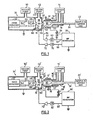
- Fig. 1 shows a plasma tube 10 around which is wound an electrical induction coil 12.
- the carrier gas e.g. argon
- used to form the plasma is supplied from a source 14 and is directed by a conduit 16 into the plasma tube 10.
- a further stream of the carrier gas is directed from the source 14 through an inner tube 18 within the plasma tube 10 and exits via a flared end 20 just upstream of the coil 12.
- the sample gas containing the trace substance to be analyzed is supplied in a carrier gas, e.g. argon, from source 22 and is fed into the plasma tube 10 through a tube 24 within and coaxial with the tube 18.
- a carrier gas e.g. argon
- the coil 12 normally has a small number of turns (four turns are shown in the drawing) and is supplied with RF power from an RF generator 26 which may include an impedance matching network 28.
- the RF power fed to the coil 12 varies depending on the nature of the plasma required and may range between 200 and 10,000 watts.
- the RF frequency used is high, typically 27 megahertz (MHz).
- the plasma generated by this arrangement is indicated at 30 and is at atmospheric pressure.
- the plasma tube 10 is located adjacent a sampler plate 32 which defines one end wall of a vacuum chamber 34.
- Sampler plate 32 is water cooled, by means not shown.
- the plasma 30 is sampled through an orifice 36 in the sampler plate 32 into a first vacuum chamber stage 38 which is evacuated through duct 40 by a pump 42.
- the sampling orifice 36 is in practice usually machined in a separate piece called a sampler which is in good electrical contact with the sampler plate 32.
- the remaining gases from the plasma exit through the space 43 between the plasma tube 10 and the plate 32.
- the first stage 38 of the vacuum chamber 34 is separated from a second vacuum chamber stage 44 by a skimmer plate 46 containing a second orifice 48.
- the skimmer orifice is also usually machined in a separate piece called a skimmer, which is in good electrical contract with the skimmer plate 46.
- the second stage 44 of the vacuum chamber is evacuated by a vacuum pump 50.
- a mass analyzer indicated at 52.
- the mass analyzer may be a quadrupole mass spectrometer having analyzing rods 54.
- located between the rods 54 and the skimmer plate orifice 48 are conventional ion optic elements indicated at 56.
- the ion optic elements 56 may include perforated quadrupole rods having RF power only applied thereto (without any d.c. applied thereto), as shown in U.S. patent No. 4,328,420 issued to J.B. French et al, and may also include a standard bessel box lens located between such RF only rods and the analyzing rods 54.
- a sample of the RF voltage is picked off the generator 26 via lead 58, adjusted in phase at phase adjusting network 60, adjusted in amplitude in amplifier 62, and applied via lead 64 to the sampler plate 32.
- the sampler plate 32 is d.c. electrically insulated from ground by insulating ring 66 but may have a considerable capacitance to ground. No special means (of the kind shown in my above identified U.S. patent) were used to reduce the voltage swing in the plasma 24.
- the RF voltage applied to the sampler plate is in phase with the peak-to-peak voltage swing in the plasma, then the voltage difference between the sampler plate 32 and the end of the plasma 30 closest to the sampler plate 32 is reduced and arcing is eliminated.
- the phase is reversed, the voltage difference is not reduced and can in fact be increased, so that arcing is not eliminated.
- the plasma may arc not only to the sampler plate 32 at the orifice 36 but also to the skimmer plate 46 at the orifice 48. Such arcing may occur in part because the skimmer plate may be in fairly good electrical contact with the plasma 30, particularly where a large sampler orifice 36 is used.
- the RF bias itself may cause a discharge in the low pressure region in the first stage 38 of the vacuum chamber due to the RF voltage difference between these two plates. Such a discharge has many of the same deleterious effects as a discharge caused by the voltage between the plasma 30 and the sampler plate 32 or skimmer plate 46.
- the arcing between the skimmer plate 46 at orifice 48 and the plasma or adjacent elements may also be reduced or eliminated, by insulating the skimmer plate from ground by insulating ring 68, and by also biasing the skimmer plate 46 with RF.
- biasing may be applied by deriving another sample of the RF voltage from generator 26 via lead 69, passing it through a phase adjusting network 70 and an amplifier 72, and then applying it through vacuum feed through 74 and lead 75 to the skimmer plate 46, as shown in Fig. 1.
- Fig. 2 shows apparatus the same as that of Fig. 1 except as will be explained, and in which primed reference numerals indicated corresponding parts.
- the Fig. 2 arrangement differs from that of Fig. 1 in that the sampler plate 32' is not R F biased and one end of the coil 12' is not grounded. Instead the coil 12' has a ground connected to a point 76 between the ends of the coil, near the center of the coil, as shown, in accordance with the arrangement shown in my above identified patent.
- This eliminates arcing between the plasma 30' and the' sampler plate 32' at orifice 36' and therefore also eliminates the need to RF bias the sampler plate 32'.
- the skimmer plate 46' is still R F biased through the phase adjusting network 70' and the amplifier 72'.
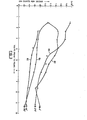
- Fig. 3 shows the results, where the voltage (RF peak-to-peak voltage) applied to the skimmer plate 46' is plotted on the X axis and the ion signal transmitted into the vacuum chamber (ion counts per second as detected by the mass spectrometer 52') is plotted on the Y axis.
- curve 80 for a phase angle of 0°
- curve 82 for a phase angle of 90°
- curve 84 for a phase angle of 180°
- curve 86 for a phase angle of 270°.
- phase angles shown in Fig. 3 are arbitrary. They are simply the phase shift settings shown on the phase shift box used as the phase shift network 70'.
- the phases shown do not represent the phase differences between the RF voltage applied to the coil 12' and that applied to the skimmer plate 46' for the following reasons.
- the generator 26' used had several stages of amplification and the lead 69' was connected to the generator 26' before its last stage of power amplification. It is expected that there was a phase shift in such last stage.
- the lead from the generator to the coil 12' was about 3 meters long, causing about a 1/3 wavelength or 120 shift between the RF voltage produced at the generator 26' and that applied to the plasma 30.
- the Fig. 3 graph was produced using a sampler orifice 36' of size .027 inches in diameter. This was a relatively small orifice, and as will be noted presently, the size of the sampler orifice 36' has a substantial influence on the effects produced by the RF bias voltage applied to the skimmer plate 46'.
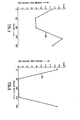
- Curve 88 in Fig. 4 was produced using the same data used to produce the Fig. 3 graph.
- Fig. 4 the ion transmission is plotted on the Y axis and the phase on the X axis.
- the same size sampler orifice was used as that for Fig. 3.
- a constant RF bias voltage of 2.32 volts peak-to-peak was applied to the skimmer plate 46'. It will be seen that the optimum ion transmission occurred at a phase setting of about 290°, and that the ratio between the best and worse ion transmissions was approximately 2.5 at the bias voltage used.
- Fig. 5 is a plot the same as that shown for Fig. 1 but with only two curves 90, 92 plotted.
- Curve 90 is for a phase setting of 0°
- curve 92 is for a phase setting of 270°.
- Fig. 5 plot a larger sampler orifice 36' of .034 inch diameter was used. It will be seen that in this arrangement the best ion transmission occurred at a much higher skimmer bias voltage of about 5.4 volts peak-to-peak. The ratio between the ion transmissions 0° and at 270° at this voltage was about 15. It is noted that the phase settings shown in Fig. 5 cannot be compared with those of Fig. 4 because a slightly different voltage dropping network (not shown) adjacent the feed through 74 was used for the Fig. 5 plot and would have produced a difference in the phase shifts.
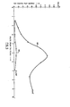
- Fig. 6 is a plot similar to that of Fig. 4 but was produced using the same data as that used to produce Fig. 5, with a sampler orifice size of .034 inches and an R F bias voltage of 5.4 volts peak-to-peak. As shown, the best ion transmission occurred at 0° (or 360°). Ion transmission appeared virtually to cease between 90° and 270°.
- ion transmission can be optimized by applying an RF bias to the skimmer plate 46', provided that the bias is of correct phase and amplitude.
- the variation of ion transmission with changes in the phase and amplitude of the RF bias is greater with a larger diameter sampler orifice 36', and that higher RF bias voltages are required with the larger diameter sampler orifice for optimum ion transmission.
- the bias signal applied to the skimmer plate 46' produces greater effects with a larger diameter sampler orifice 36' for the following reasons.
- the heating currents in the plasma 30 cannot be eliminated, and therefore there will always be an RF voltage swing in the plasma (typically of up to about 10 volts) even when the coil 12' is center tapped.
- the skimmer plate 46' is better insulated from the plasma 30'. In this situation a cool boundary layer tends to form over the sampler plate 32' and, together with the smaller orifice 36', insulates the skimmer plate 46" from the RF voltage in the plasma.
- the sampler orifice 36' is larger, the cool boundary layer is less pronounced and in addition the skimmer plate 46' is in better electrical contact with the plasma 30' and is driven harder thereby.
- the plasma 30' would be negative with respect to the skimmer plate 46' and formation of a positive ion beam from the plasma through the skimmer orifice 48' may be expected to be inhibited. If the RF bias applied to the skimmer plate 46' is always negative with respect to the plasma, then ion extraction may be favoured over the entire RF cycle rather than over only half of the cycle. This may account for the approximately two-fold increase between the best grounded and RF biased cases.
- the ion optic system 56' may more favourably accept an ion beam if the skimmer plate 46' has a constant potential difference with respect to the plasma 30'. Ion optic transmission depends on the ion energy, which depends partly on the voltage on the skimmer plate 46' and partly on the voltage in the plasma. If the voltage difference between the skimmer plate 46' and the plasma 30' is kept constant, then it appears that the ion optic system 56' may be better able to transmit a consistently high proportion of the ions which enter it, as opposed to an arrangement in which the voltage is constantly varying.
- ion optics lens systems may more favorably accept an ion beam if the skimmer plate 46' is a few volts positive or negative with respect to the plasma.
- a suitable RF bias may be expected to optimize the ion transmission through the ion optics lens system 56.
- the background noise level varied with the RF bias (but remained relatively low in all cases). The reasons for this effect are not clear but two possibilities are suggested. The first is that the residual voltage swing remaining in the plasma may have been sufficient to cause a very weak discharge in the first stage 38' of the vacuum chamber (where the pressure was about 1 torr, as compared with about 10- 5 torr in most of the second stage). Biasing the skimmer plate correctly would reduce or remove this discharge, reducing the noise.
- the first ion optic element near the base of the skimmer plate
- the first ion optic element had a relatively high voltage applied to it and was in a region of fairly high gas density because of the jet of gas travelling through the skimmer orifice 48'.
- the discharge from the first ion optic element to the skimmer plate would be initiated by free electrons from the plasma 30'. If the skimmer is biased so as to permit a positive ion beam to be produced at all times during the full cycle, transmission of free electrons from the plasma may be inhibited and a breakdown at the first lens element reduced.
- bias voltage or voltages were shown as derived from the generator 26 or 26' and were therefore phase locked to the RF voltage applied to the coil 12 or 12', a separate bias voltage generator can be used, phase locked to the generator 26 or 26'.
Landscapes
- Physics & Mathematics (AREA)
- Engineering & Computer Science (AREA)
- Plasma & Fusion (AREA)
- Chemical & Material Sciences (AREA)
- Analytical Chemistry (AREA)
- Other Investigation Or Analysis Of Materials By Electrical Means (AREA)
- Electron Tubes For Measurement (AREA)
Applications Claiming Priority (2)
| Application Number | Priority Date | Filing Date | Title |
|---|---|---|---|
| CA000479934A CA1246246A (fr) | 1985-04-24 | 1985-04-24 | Methode et appareil a polarisation rf pour echantillonner un plasma dans une chambre a vide |
| CA479934 | 1985-04-24 |
Publications (3)
| Publication Number | Publication Date |
|---|---|
| EP0199455A2 true EP0199455A2 (fr) | 1986-10-29 |
| EP0199455A3 EP0199455A3 (en) | 1987-05-13 |
| EP0199455B1 EP0199455B1 (fr) | 1989-08-30 |
Family
ID=4130351
Family Applications (1)
| Application Number | Title | Priority Date | Filing Date |
|---|---|---|---|
| EP19860301974 Expired EP0199455B1 (fr) | 1985-04-24 | 1986-03-18 | Introduction d'un échantillon de plasma dans une chambre à vide |
Country Status (4)
| Country | Link |
|---|---|
| EP (1) | EP0199455B1 (fr) |
| JP (1) | JPH0821363B2 (fr) |
| CA (1) | CA1246246A (fr) |
| DE (1) | DE3665379D1 (fr) |
Cited By (4)
| Publication number | Priority date | Publication date | Assignee | Title |
|---|---|---|---|---|
| WO1989012313A1 (fr) * | 1988-06-03 | 1989-12-14 | Vg Instruments Group Limited | Spectrometre de masse a plasma a haute resolution |
| WO1990009031A1 (fr) * | 1989-01-30 | 1990-08-09 | Vg Instruments Group Limited | Spectrometre de masse a plasma |
| FR2656926A1 (fr) * | 1990-01-05 | 1991-07-12 | Air Liquide | Perfectionnement au procede d'analyse elementaire d'un echantillon par spectrometrie de masse couplee a un plasma induit par haute frequence et a l'installation pour la mise en óoeuvre de ce procede. |
| US5229605A (en) * | 1990-01-05 | 1993-07-20 | L'air Liquide, Societe Anonyme Pour L'etude Et L'exploitation Des Procedes Georges Claude | Process for the elementary analysis of a specimen by high frequency inductively coupled plasma mass spectrometry and apparatus for carrying out this process |
Families Citing this family (4)
| Publication number | Priority date | Publication date | Assignee | Title |
|---|---|---|---|---|
| JPS62219452A (ja) * | 1986-03-20 | 1987-09-26 | Yokogawa Electric Corp | 高周波誘導結合プラズマ・質量分析計 |
| JP2568253B2 (ja) * | 1988-07-01 | 1996-12-25 | 日本電子株式会社 | 高周波誘導結合プラズマ質量分析装置 |
| JP2731512B2 (ja) * | 1994-10-07 | 1998-03-25 | 株式会社日立製作所 | プラズマ質量分析計 |
| GB2636826B (en) * | 2023-12-22 | 2026-03-18 | Thermo Fisher Scient Bremen Gmbh | Spacer for an orifice element |
Family Cites Families (1)
| Publication number | Priority date | Publication date | Assignee | Title |
|---|---|---|---|---|
| CA1189201A (fr) * | 1982-12-08 | 1985-06-18 | Donald J. Douglas | Methode et dispositif d'echantillonnage d'un plasma dans un tube sous vide |
-
1985
- 1985-04-24 CA CA000479934A patent/CA1246246A/fr not_active Expired
-
1986
- 1986-03-18 EP EP19860301974 patent/EP0199455B1/fr not_active Expired
- 1986-03-18 DE DE8686301974T patent/DE3665379D1/de not_active Expired
- 1986-04-24 JP JP61095855A patent/JPH0821363B2/ja not_active Expired - Lifetime
Cited By (6)
| Publication number | Priority date | Publication date | Assignee | Title |
|---|---|---|---|---|
| WO1989012313A1 (fr) * | 1988-06-03 | 1989-12-14 | Vg Instruments Group Limited | Spectrometre de masse a plasma a haute resolution |
| US5068534A (en) * | 1988-06-03 | 1991-11-26 | Vg Instruments Group Limited | High resolution plasma mass spectrometer |
| WO1990009031A1 (fr) * | 1989-01-30 | 1990-08-09 | Vg Instruments Group Limited | Spectrometre de masse a plasma |
| US5051584A (en) * | 1989-01-30 | 1991-09-24 | Vg Instruments Group Limited | Plasma mass spectrometer |
| FR2656926A1 (fr) * | 1990-01-05 | 1991-07-12 | Air Liquide | Perfectionnement au procede d'analyse elementaire d'un echantillon par spectrometrie de masse couplee a un plasma induit par haute frequence et a l'installation pour la mise en óoeuvre de ce procede. |
| US5229605A (en) * | 1990-01-05 | 1993-07-20 | L'air Liquide, Societe Anonyme Pour L'etude Et L'exploitation Des Procedes Georges Claude | Process for the elementary analysis of a specimen by high frequency inductively coupled plasma mass spectrometry and apparatus for carrying out this process |
Also Published As
| Publication number | Publication date |
|---|---|
| EP0199455B1 (fr) | 1989-08-30 |
| DE3665379D1 (en) | 1989-10-05 |
| CA1246246A (fr) | 1988-12-06 |
| JPH0821363B2 (ja) | 1996-03-04 |
| JPS61248348A (ja) | 1986-11-05 |
| EP0199455A3 (en) | 1987-05-13 |
Similar Documents
| Publication | Publication Date | Title |
|---|---|---|
| US4682026A (en) | Method and apparatus having RF biasing for sampling a plasma into a vacuum chamber | |
| US6545270B2 (en) | Plasma mass spectrometer | |
| EP0407539B1 (fr) | Spectrometre de masse a plasma | |
| JP4511505B2 (ja) | 軸電界を有する分析計 | |
| US6005245A (en) | Method and apparatus for ionizing a sample under atmospheric pressure and selectively introducing ions into a mass analysis region | |
| US20150130348A1 (en) | Magnetically Enhanced, Inductively coupled Plasma Source For a Focused Ion Beam System | |
| JP2724416B2 (ja) | 高分解能プラズマ質量スペクトロメータ | |
| JP2013545243A (ja) | 質量分析法における改良及び質量分析法に関係する改良 | |
| US11270877B2 (en) | Multipole ion guide | |
| EP0199455B1 (fr) | Introduction d'un échantillon de plasma dans une chambre à vide | |
| JP3284886B2 (ja) | イオン源及びイオン注入装置 | |
| EP0112004B1 (fr) | Méthode et dispositif pour l'échantillonnage d'un plasma dans une chambre à vide | |
| Saprykin et al. | Characterization and optimization of a radiofrequency glow discharge ion source for a high resolution mass spectrometer | |
| US20020089332A1 (en) | Probe assembly for detecting an ion in a plasma generated in an ion source | |
| KR102941034B1 (ko) | 절연 공심 변압기를 이용한 임피던스 정합 회로 및 이를 포함하는 질량 분석기 | |
| US20240364293A1 (en) | Impedance Matching Circuit Using Insulated Air Core Transformer and Mass Spectrometer Including the Same | |
| US20180330909A1 (en) | Inductively coupled plasma ion source with tunable radio requency power | |
| USRE33386E (en) | Method and apparatus for sampling a plasma into a vacuum chamber | |
| JP2001522129A (ja) | 信号対雑音比を改善するための低レベル分解dc入力を有する質量分光器の動作方法 | |
| JP2926782B2 (ja) | 高周波誘導結合プラズマ質量分析装置 | |
| Ishikawa et al. | Low energy components of ions extracted from an RF ion source |
Legal Events
| Date | Code | Title | Description |
|---|---|---|---|
| PUAI | Public reference made under article 153(3) epc to a published international application that has entered the european phase |
Free format text: ORIGINAL CODE: 0009012 |
|
| AK | Designated contracting states |
Kind code of ref document: A2 Designated state(s): DE FR GB |
|
| PUAL | Search report despatched |
Free format text: ORIGINAL CODE: 0009013 |
|
| AK | Designated contracting states |
Kind code of ref document: A3 Designated state(s): DE FR GB |
|
| 17P | Request for examination filed |
Effective date: 19870720 |
|
| 17Q | First examination report despatched |
Effective date: 19881012 |
|
| GRAA | (expected) grant |
Free format text: ORIGINAL CODE: 0009210 |
|
| AK | Designated contracting states |
Kind code of ref document: B1 Designated state(s): DE FR GB |
|
| REF | Corresponds to: |
Ref document number: 3665379 Country of ref document: DE Date of ref document: 19891005 |
|
| ET | Fr: translation filed | ||
| PLBE | No opposition filed within time limit |
Free format text: ORIGINAL CODE: 0009261 |
|
| STAA | Information on the status of an ep patent application or granted ep patent |
Free format text: STATUS: NO OPPOSITION FILED WITHIN TIME LIMIT |
|
| 26N | No opposition filed | ||
| REG | Reference to a national code |
Ref country code: GB Ref legal event code: IF02 |
|
| PGFP | Annual fee paid to national office [announced via postgrant information from national office to epo] |
Ref country code: FR Payment date: 20050308 Year of fee payment: 20 |
|
| PGFP | Annual fee paid to national office [announced via postgrant information from national office to epo] |
Ref country code: DE Payment date: 20050310 Year of fee payment: 20 |
|
| PGFP | Annual fee paid to national office [announced via postgrant information from national office to epo] |
Ref country code: GB Payment date: 20050316 Year of fee payment: 20 |
|
| PG25 | Lapsed in a contracting state [announced via postgrant information from national office to epo] |
Ref country code: GB Free format text: LAPSE BECAUSE OF EXPIRATION OF PROTECTION Effective date: 20060317 |
|
| REG | Reference to a national code |
Ref country code: GB Ref legal event code: PE20 |