EP0199693A2 - Alimentation en liquide de refroidissement d'un outil de coupe rotatif - Google Patents
Alimentation en liquide de refroidissement d'un outil de coupe rotatif Download PDFInfo
- Publication number
- EP0199693A2 EP0199693A2 EP86850128A EP86850128A EP0199693A2 EP 0199693 A2 EP0199693 A2 EP 0199693A2 EP 86850128 A EP86850128 A EP 86850128A EP 86850128 A EP86850128 A EP 86850128A EP 0199693 A2 EP0199693 A2 EP 0199693A2
- Authority
- EP
- European Patent Office
- Prior art keywords
- supply
- coolant
- bore
- ring
- axis
- Prior art date
- Legal status (The legal status is an assumption and is not a legal conclusion. Google has not performed a legal analysis and makes no representation as to the accuracy of the status listed.)
- Granted
Links
Images

Classifications
-
- F—MECHANICAL ENGINEERING; LIGHTING; HEATING; WEAPONS; BLASTING
- F16—ENGINEERING ELEMENTS AND UNITS; GENERAL MEASURES FOR PRODUCING AND MAINTAINING EFFECTIVE FUNCTIONING OF MACHINES OR INSTALLATIONS; THERMAL INSULATION IN GENERAL
- F16L—PIPES; JOINTS OR FITTINGS FOR PIPES; SUPPORTS FOR PIPES, CABLES OR PROTECTIVE TUBING; MEANS FOR THERMAL INSULATION IN GENERAL
- F16L27/00—Adjustable joints; Joints allowing movement
- F16L27/08—Adjustable joints; Joints allowing movement allowing adjustment or movement only about the axis of one pipe
- F16L27/087—Joints with radial fluid passages
- F16L27/093—Joints with radial fluid passages of the "banjo" type, i.e. pivoting right-angle couplings
-
- B—PERFORMING OPERATIONS; TRANSPORTING
- B23—MACHINE TOOLS; METAL-WORKING NOT OTHERWISE PROVIDED FOR
- B23Q—DETAILS, COMPONENTS, OR ACCESSORIES FOR MACHINE TOOLS, e.g. ARRANGEMENTS FOR COPYING OR CONTROLLING; MACHINE TOOLS IN GENERAL CHARACTERISED BY THE CONSTRUCTION OF PARTICULAR DETAILS OR COMPONENTS; COMBINATIONS OR ASSOCIATIONS OF METAL-WORKING MACHINES, NOT DIRECTED TO A PARTICULAR RESULT
- B23Q11/00—Accessories fitted to machine tools for keeping tools or parts of the machine in good working condition or for cooling work; Safety devices specially combined with or arranged in, or specially adapted for use in connection with, machine tools
- B23Q11/10—Arrangements for cooling or lubricating tools or work
-
- B—PERFORMING OPERATIONS; TRANSPORTING
- B23—MACHINE TOOLS; METAL-WORKING NOT OTHERWISE PROVIDED FOR
- B23Q—DETAILS, COMPONENTS, OR ACCESSORIES FOR MACHINE TOOLS, e.g. ARRANGEMENTS FOR COPYING OR CONTROLLING; MACHINE TOOLS IN GENERAL CHARACTERISED BY THE CONSTRUCTION OF PARTICULAR DETAILS OR COMPONENTS; COMBINATIONS OR ASSOCIATIONS OF METAL-WORKING MACHINES, NOT DIRECTED TO A PARTICULAR RESULT
- B23Q2220/00—Machine tool components
- B23Q2220/008—Rotatable tool holders coupled in parallel to a non rotating accessory
-
- Y—GENERAL TAGGING OF NEW TECHNOLOGICAL DEVELOPMENTS; GENERAL TAGGING OF CROSS-SECTIONAL TECHNOLOGIES SPANNING OVER SEVERAL SECTIONS OF THE IPC; TECHNICAL SUBJECTS COVERED BY FORMER USPC CROSS-REFERENCE ART COLLECTIONS [XRACs] AND DIGESTS
- Y10—TECHNICAL SUBJECTS COVERED BY FORMER USPC
- Y10T—TECHNICAL SUBJECTS COVERED BY FORMER US CLASSIFICATION
- Y10T137/00—Fluid handling
- Y10T137/7722—Line condition change responsive valves
- Y10T137/7837—Direct response valves [i.e., check valve type]
- Y10T137/7879—Resilient material valve
- Y10T137/788—Having expansible port
- Y10T137/7882—Having exit lip
- Y10T137/7885—Multiple slit
-
- Y—GENERAL TAGGING OF NEW TECHNOLOGICAL DEVELOPMENTS; GENERAL TAGGING OF CROSS-SECTIONAL TECHNOLOGIES SPANNING OVER SEVERAL SECTIONS OF THE IPC; TECHNICAL SUBJECTS COVERED BY FORMER USPC CROSS-REFERENCE ART COLLECTIONS [XRACs] AND DIGESTS
- Y10—TECHNICAL SUBJECTS COVERED BY FORMER USPC
- Y10T—TECHNICAL SUBJECTS COVERED BY FORMER US CLASSIFICATION
- Y10T408/00—Cutting by use of rotating axially moving tool
- Y10T408/44—Cutting by use of rotating axially moving tool with means to apply transient, fluent medium to work or product
-
- Y—GENERAL TAGGING OF NEW TECHNOLOGICAL DEVELOPMENTS; GENERAL TAGGING OF CROSS-SECTIONAL TECHNOLOGIES SPANNING OVER SEVERAL SECTIONS OF THE IPC; TECHNICAL SUBJECTS COVERED BY FORMER USPC CROSS-REFERENCE ART COLLECTIONS [XRACs] AND DIGESTS
- Y10—TECHNICAL SUBJECTS COVERED BY FORMER USPC
- Y10T—TECHNICAL SUBJECTS COVERED BY FORMER US CLASSIFICATION
- Y10T408/00—Cutting by use of rotating axially moving tool
- Y10T408/44—Cutting by use of rotating axially moving tool with means to apply transient, fluent medium to work or product
- Y10T408/45—Cutting by use of rotating axially moving tool with means to apply transient, fluent medium to work or product including Tool with duct
- Y10T408/455—Conducting channel extending to end of Tool
-
- Y—GENERAL TAGGING OF NEW TECHNOLOGICAL DEVELOPMENTS; GENERAL TAGGING OF CROSS-SECTIONAL TECHNOLOGIES SPANNING OVER SEVERAL SECTIONS OF THE IPC; TECHNICAL SUBJECTS COVERED BY FORMER USPC CROSS-REFERENCE ART COLLECTIONS [XRACs] AND DIGESTS
- Y10—TECHNICAL SUBJECTS COVERED BY FORMER USPC
- Y10T—TECHNICAL SUBJECTS COVERED BY FORMER US CLASSIFICATION
- Y10T409/00—Gear cutting, milling, or planing
- Y10T409/30—Milling
- Y10T409/303976—Milling with means to control temperature or lubricate
- Y10T409/304032—Cutter or work
Definitions
- the present invention is related to a coolant supply apparatus for a cutting tool for cutting a workpiece wherein there is relative cutting motion about an axis of rotation between a cutting member or plate mounted upon a tool shank and a workpiece.
- the coolant is supplied from a coolant supply means to the cutting member by means of aligned bores in a coolant supply member, coolant supply ring and tool shank.
- the present invention is also related to a cutting tool including such a coolant supply apparatus and a flexible valve for use with such apparatus.
- An object of the Eckle apparatus is to provide a system of the type described therein which provides automatic coupling of the coolant delivery apparatus during the cutting plate interchanging process. This is done by supplying a cooling medium to the cutting plates using a supply ring which is automatically connected to and disconnected from a coupling head during cutting plate changes. More particularly, when one cutting member has been replaced- by another and the tool shank is caused to rotate, the supply ring is designed to rotate in the same direction by the friction between the tool shank and the supply ring which is positioned on the tool shank.
- a sealing surface of a coupling piece radially projecting from the supply ring comes into engagement with a sealing surface of a coupling head so that coolant can pass through bores in the coupling head, coupling piece and supply ring and then on through a bore in the tool shank to the cutting member.
- this apparatus requires that the sealing surfaces be disposed at specifically identified acute angles to assure proper bore alignment and minimize leakage.
- the sealing surfaces must be forced or snapped into sealing engagement with each other by the rotation of the tool shank.
- This invention achieves these and other results by providing a coolant supply apparatus for a cutting tool for cutting a workpiece wherein there is relative cutting motion about an axis of rotation between a cutting member or plate mounted upon a tool shank having a tool bore and a workpiece and wherein coolant is supplied from a coolant supply means through a ring bore defined by a ring bore wall which extends from an outer peripheral surface, to an inner peripheral surface, of a coolant supply ring rotatably mounted upon the tool shank and through the tool bore to the cutting member.
- a coolant supply member is provided for coupling to the cutting tool.
- the coolant supply member has a supply inlet for coupling to the coolant supply means, a supply outlet, and a supply bore defined by a supply bore wall extending from the supply inlet to the supply outlet.
- the supply outlet is spaced from the peripheral surface of the ring when the coolant supply member is coupled to the cutting tool.
- a valve means is provided coupled to the supply member adjacent the supply outlet for substantially preventing leakage between the supply bore and the ring bore when the supply member is coupled to the cutting tool and the supply and ring bores are aligned and coolant is being supplied by the coolant supply means.
- the valve means is flexible so that it is caused to extend towards the outer peripheral surface of the ring and engage the ring bore wall when the supply member is coupled to the cutting tool and the ring is rotated to align the ring bore with the supply bore and coolant is supplied by the coolant supply means.
- the valve means is disengaged from the ring bore wall and retracted from the outer peripheral surface of the ring when the coolant is not being supplied by the coolant supply means.
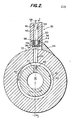
- Figure 1 depicts a machine or cutting tool 2 for cutting a workpiece 4 wherein there is relative cutting motion about an axis of rotation 6 between a cutting member 8 mounted upon a tool shank 10 having a tool bore 12 and workpiece 4.
- a cutting tool is of the type described in United States Patent No. 4,392,761.
- tool shank 10 having cutting members 8 attached thereto is caused to rotate about axis 6 in a manner known in the art.
- tool shank 10 can be caused to rotate in a known manner by a motor which is not shown.
- the ring 18 includes an inner peripheral surface 20 and an outer peripheral surface 22 having an inlet connector 24 extending therefrom.
- the inlet connector 24 is only shown in Figures 2 and 3.
- Ring 18 includes a coolant supply ring bore 26 defined by a ring bore wall 28 which extends from inner surface 20 to outer surface 22.
- the relationship between ring 18 and tool shank 10 is such that when the shank is caused to rotate the supply ring. will be caused to rotate in the same direction as. a result of friction between the outer surface 30 of shank 10 and the surface 20 of ring 18.
- continued rotation of the ring 18 is terminated when the ring is rotated to the extent that inlet connector 24 engages the stationary coolant supply member'32 described in greater detail hereinafter.
- Coolant supply member 32 which is coupled to the cutting tool 2, includes a supply inlet 34 coupled to a coolant supply means including hose 36 in a known manner.
- Supply member 32 also includes a supply outlet 38 and a supply bore 40 defined by a supply bore wall 42 which extends from the supply inlet 34 to the supply outlet 38.
- Supply outlet 38 is spaced from the peripheral surface 22 of ring 18 so that ring 18 is free to rotate without incurring friction which would otherwise be incurred if surface 22 was in contact with outlet 38.
- tool shank .10 and ring l8 coupled thereto are rotated until inlet connector 24 engages supply outlet 38 at which point the tool shank will continue to rotate so that the cutting members 8 rotate to cut the workpiece 4, and the ring will come to rest.
- Connector 24 and outlet 38 are constructed so that at such rest position ring bore 26 will be aligned with supply bore 40.
- coolant is supplied from the coolant supply means at hose 36 and passes through supply bore 40, ring bore 26,one or more radial bores 27 in the tool shank 10, and tool shank bore 12 to the cutting members 8. .
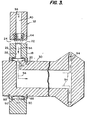
- a valve means is coupled to the supply member 32 adjacent the supply outlet 38 for substantially preventing leakage between the supply bore 40 and the ring bore 26 when the bores 40 and 26 are aligned and coolant is being supplied by the coolant supply means.
- a generally cup shaped valve member 44 is attached to the supply member 32.
- Valve member 44 includes an axis 46 extending in a longitudinal direction and coinciding with the supply axis 48 of supply member 32.
- the valve member 44 includes an open end 50 upstream of the supply bore 40 and an end 52 downstream of the supply bore.
- the end 52 of the valve member. 44 is normally in a closed position as shown is solid lines in Figures 2 and 3.
- the normally closed end 52 includes at least one flexible closure 54 which relative to axis 46 normally extends radially as shown in Figures 2 and 3.
- the flexible closure 54 can be flexed to extend axially into ring bore 26 so as to engage.the ring bore wall 28, as shown in phantom lines in Figures 2 and 3,when the supply bore 40 and ring bore 26 are in axial alignment and coolant is being supplied by the coolant supply means.
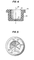
- the flexible closure comprises a plurality of flexible sections.
- Figures -4 and 5 depict six such sections 54a, 54b, 54c, 54d, 54e and 54f, each of such sections preferably being wedge shaped as shown in the drawings.
- the valve member comprises a flexible material.
- An example of such a material is, without limitation, neoprene.
- the cup shaped member is mounted to the supply member 32 by means of a mounting flange.
- the cup shaped valve member 44 includes a flange 56 located adjacent the-open end 50.
- Flange 56 extends radially outward relative to the axis 46 and into a groove 58 which extends circumferentially about supply bore wall 42 located adjacent the supply outlet 38.
- valve member of the type thus far discussed provides, without limitation, one form of valve means, the valve means being flexible as described so that the valve means is caused to extend towards the outer peripheral surface 22 of the ring 18 and engage the ring bore wall 28 when the ring 18 is rotated to align the ring bore 26 with the supply bore 40 and coolant is supplied by the coolant supply means at hose 36.
- the valve means is disengaged from the ring bore wall 28 and retracted from the outer peripheral surface 22 of the ring 18 when coolant is not being supplied by the coolant supply means.
- the supply member 32 includes a mounting block 60.
- block 60 can be coupled to the cutting tool 2 as, for example, by means of bolts 62, only one of which is shown in the drawings.
- An elongated cylindrical pipe holder 64 is coupled to the mounting block, pipe holder 64 extending through a cylindrical opening 66 and being held in place by a pipe lock 68 and locking screw 70.
- Pipe holder 64 extends along a first longitudinal axis 72 which is substantially parallel to the axis of rotation 6 when the mounting block 60 is coupled to the cutting tool 2 as shown.
- An elongated cylindrical supply pipe 74 is also provided.
- Supply pipe 74 is slideably:coupled to the pipe holder, supply pipe 74 extending through a cylindrical opening 76 in the pipe holder.64 and being held in place by a pipe lock 78 and locking screw 80. Loosening of screw 80 allows the supply pipe 74 to slide along a second longitudinal axis 82 towards and away from the outer peripheral surface 22 of ring 18 to the extent desired to control the spacing in the direction identified by arrow 84 between surface 22 and supply outlet 38.
- axis 82 ooincides with axis 48.
- the supply pipe 74 includes the supply inlet 34 at one end, the supply outlet 38 at the other end,and the supply bore 40 defined by supply bore wall 42 extending from inlet 34 to outlet 38.
- pipe holder 64 is moveably coupled to the mounting block 60 so that loosening of screw 70 allows the pipe holder to slide, for example, along axis 72 to the extent desired to control the location, in the direction, for example, identified by arrow 86, of the supply outlet 38 along surface 22.
- supply ring 18 is mounted upon fool shank 10 forming a-tight fit as described herein.
Landscapes
- Engineering & Computer Science (AREA)
- General Engineering & Computer Science (AREA)
- Mechanical Engineering (AREA)
- Auxiliary Devices For Machine Tools (AREA)
Applications Claiming Priority (2)
| Application Number | Priority Date | Filing Date | Title |
|---|---|---|---|
| US723653 | 1985-04-16 | ||
| US06/723,653 US4668135A (en) | 1985-04-16 | 1985-04-16 | Coolant supply in rotating cutting tool |
Publications (3)
| Publication Number | Publication Date |
|---|---|
| EP0199693A2 true EP0199693A2 (fr) | 1986-10-29 |
| EP0199693A3 EP0199693A3 (en) | 1987-06-03 |
| EP0199693B1 EP0199693B1 (fr) | 1990-02-21 |
Family
ID=24907133
Family Applications (1)
| Application Number | Title | Priority Date | Filing Date |
|---|---|---|---|
| EP19860850128 Expired - Lifetime EP0199693B1 (fr) | 1985-04-16 | 1986-04-14 | Alimentation en liquide de refroidissement d'un outil de coupe rotatif |
Country Status (5)
| Country | Link |
|---|---|
| US (1) | US4668135A (fr) |
| EP (1) | EP0199693B1 (fr) |
| JP (1) | JPS61288957A (fr) |
| CA (1) | CA1280627C (fr) |
| DE (1) | DE3669075D1 (fr) |
Cited By (2)
| Publication number | Priority date | Publication date | Assignee | Title |
|---|---|---|---|---|
| US5417969A (en) * | 1991-09-20 | 1995-05-23 | Baxter International Inc. | Process for reducing the thrombogenicity of biomaterials |
| US5613812A (en) * | 1994-12-14 | 1997-03-25 | Bristol Tool & Gauge Engineering Limited | Rotary coolant adaptor |
Families Citing this family (9)
| Publication number | Priority date | Publication date | Assignee | Title |
|---|---|---|---|---|
| US5413438A (en) * | 1986-03-17 | 1995-05-09 | Turchan; Manuel C. | Combined hole making and threading tool |
| US5183363A (en) * | 1992-07-17 | 1993-02-02 | Gte Valenite Corporation | Non-contact coolant supply apparatus |
| US5272945A (en) * | 1992-08-26 | 1993-12-28 | Kennametal Inc. | Toolholder assembly and method |
| US5419661A (en) * | 1994-07-25 | 1995-05-30 | Kennametal Inc. | Rotatable tooholder having a stationary, through-center coolant feed system |
| DE19621240C2 (de) * | 1996-05-25 | 1998-05-28 | Chiron Werke Gmbh | Werkzeughalter mit Kühlmittelrohr |
| US5672035A (en) * | 1996-09-16 | 1997-09-30 | Chrysler Corporation | Turn broaching machine |
| AT502377B1 (de) | 2005-09-26 | 2007-03-15 | Asen Norbert Ing | Grundkörper für ein rotierendes schleif- bzw. schneidwerkzeug sowie daraus hergestelltes schleif- bzw. schneidwerkzeug |
| US8128323B2 (en) * | 2009-04-14 | 2012-03-06 | Planet Products Corporation | Driven tool assembly |
| JP7256605B2 (ja) * | 2018-04-04 | 2023-04-12 | 川崎重工業株式会社 | 研削ホルダ、研削工具及び研削装置 |
Family Cites Families (8)
| Publication number | Priority date | Publication date | Assignee | Title |
|---|---|---|---|---|
| US2335832A (en) * | 1942-03-02 | 1943-11-30 | Bendix Westinghouse Automotive | Fluid coupling |
| US3245428A (en) * | 1963-11-08 | 1966-04-12 | Berg Mfg & Sales Co | Flexible seal for use in a gladhand assembly |
| US3370659A (en) * | 1964-09-25 | 1968-02-27 | Gatien Paul Germain | Drill rod and bit including one-way valve structure therein |
| US3689168A (en) * | 1971-12-30 | 1972-09-05 | Henry Persson | Mountable chip breaker and flute cleaner for rotating twist drills |
| JPS5642769A (en) * | 1979-09-12 | 1981-04-21 | Shin Gijutsu Kaihatsu Kk | Check valve for drilling pipe |
| DE8012959U1 (de) * | 1980-05-13 | 1981-11-12 | Komet Stahlhalter- Und Werkzeugfabrik Robert Breuning Gmbh, 7122 Besigheim | Kühleinrichtung für rotierende Schneidwerkzeuge für die spanende Metallbearbeitung, insbesondere für Borhrwerkzeuge |
| DE3266850D1 (en) * | 1981-09-25 | 1985-11-14 | Rieter Ag Maschf | Device for conveying a fluid under pressure to a shaft |
| DE8224671U1 (de) * | 1982-09-01 | 1984-02-09 | Komet Stahlhalter- Und Werkzeugfabrik Robert Breuning Gmbh, 7122 Besigheim | Vorrichtung zur Kühlmittelzufuhr zu mit Kühlmittelkanälen versehenen, rotierenden Schneidwerkzeugen für die spanende Metallbearbeitung, insbesondere Bohrwerkzeuge |
-
1985
- 1985-04-16 US US06/723,653 patent/US4668135A/en not_active Expired - Fee Related
-
1986
- 1986-04-14 DE DE8686850128T patent/DE3669075D1/de not_active Expired - Lifetime
- 1986-04-14 EP EP19860850128 patent/EP0199693B1/fr not_active Expired - Lifetime
- 1986-04-15 CA CA 506706 patent/CA1280627C/fr not_active Expired - Lifetime
- 1986-04-16 JP JP61086211A patent/JPS61288957A/ja active Pending
Cited By (2)
| Publication number | Priority date | Publication date | Assignee | Title |
|---|---|---|---|---|
| US5417969A (en) * | 1991-09-20 | 1995-05-23 | Baxter International Inc. | Process for reducing the thrombogenicity of biomaterials |
| US5613812A (en) * | 1994-12-14 | 1997-03-25 | Bristol Tool & Gauge Engineering Limited | Rotary coolant adaptor |
Also Published As
| Publication number | Publication date |
|---|---|
| JPS61288957A (ja) | 1986-12-19 |
| EP0199693A3 (en) | 1987-06-03 |
| DE3669075D1 (de) | 1990-03-29 |
| EP0199693B1 (fr) | 1990-02-21 |
| US4668135A (en) | 1987-05-26 |
| CA1280627C (fr) | 1991-02-26 |
Similar Documents
| Publication | Publication Date | Title |
|---|---|---|
| US4668135A (en) | Coolant supply in rotating cutting tool | |
| EP0186811B1 (fr) | Joint d'étanchéité mécanique à bague formée par des segments | |
| US5344164A (en) | Mechanical seals | |
| US3957276A (en) | Mechanical seal with pressurized lubrication pockets | |
| US4294453A (en) | Mechanical seal | |
| GB2140334A (en) | Coolant delivery device | |
| US5072948A (en) | Seal assembly for a high speed machining system | |
| AU724735B2 (en) | A seal for a pump, and a pump comprising the seal | |
| US4636118A (en) | Coolant supply extension member in rotating cutting tool | |
| US20150198172A1 (en) | Double mechanical seal for centrifugal pump | |
| EP0629462B1 (fr) | Porte-outil muni d'un approvisionnement d'un réfrigérant | |
| US5324048A (en) | Mechanical seals | |
| EP0157720B1 (fr) | Logement pour siège de soupape avec surface d'appui sans rupture | |
| WO1995001517A1 (fr) | Accouplement de corps de rotor a des tourillons | |
| US4688807A (en) | Shaft seal | |
| CA2167012C (fr) | Soupape en ligne a monter sur une canalisation de fluide sous pression | |
| US5651567A (en) | Multi-passage bearingless fluid coupler | |
| AU731482B2 (en) | Toolholder having impeller-type coolant inducer | |
| EP0727026B1 (fr) | Raccord de tuyaux | |
| EP0207031B1 (fr) | Conduite d'alimentation en agent de réfrigération pour outil coupant rotatif | |
| EP0435955B1 (fr) | Unite de raccordement | |
| US4029125A (en) | Snap-fitting pipe connecting device | |
| CA1227820A (fr) | Accouplement | |
| EP0483236B1 (fr) | Vanne de deviation rotative possedant des interfaces plates | |
| EP0415591B1 (fr) | Joint d'étanchéité pour système d'usinage à grande vitesse |
Legal Events
| Date | Code | Title | Description |
|---|---|---|---|
| PUAI | Public reference made under article 153(3) epc to a published international application that has entered the european phase |
Free format text: ORIGINAL CODE: 0009012 |
|
| AK | Designated contracting states |
Kind code of ref document: A2 Designated state(s): BE DE FR GB IT NL SE |
|
| PUAL | Search report despatched |
Free format text: ORIGINAL CODE: 0009013 |
|
| AK | Designated contracting states |
Kind code of ref document: A3 Designated state(s): BE DE FR GB IT NL SE |
|
| 17P | Request for examination filed |
Effective date: 19871126 |
|
| 17Q | First examination report despatched |
Effective date: 19880620 |
|
| GRAA | (expected) grant |
Free format text: ORIGINAL CODE: 0009210 |
|
| AK | Designated contracting states |
Kind code of ref document: B1 Designated state(s): BE DE FR GB IT NL SE |
|
| RAP2 | Party data changed (patent owner data changed or rights of a patent transferred) |
Owner name: GTE VALENITE CORPORATION |
|
| REF | Corresponds to: |
Ref document number: 3669075 Country of ref document: DE Date of ref document: 19900329 |
|
| ET | Fr: translation filed | ||
| ITF | It: translation for a ep patent filed | ||
| PLBE | No opposition filed within time limit |
Free format text: ORIGINAL CODE: 0009261 |
|
| STAA | Information on the status of an ep patent application or granted ep patent |
Free format text: STATUS: NO OPPOSITION FILED WITHIN TIME LIMIT |
|
| BECN | Be: change of holder's name |
Effective date: 19900221 |
|
| 26N | No opposition filed | ||
| PGFP | Annual fee paid to national office [announced via postgrant information from national office to epo] |
Ref country code: SE Payment date: 19910327 Year of fee payment: 6 |
|
| PGFP | Annual fee paid to national office [announced via postgrant information from national office to epo] |
Ref country code: GB Payment date: 19910405 Year of fee payment: 6 |
|
| PGFP | Annual fee paid to national office [announced via postgrant information from national office to epo] |
Ref country code: FR Payment date: 19910424 Year of fee payment: 6 Ref country code: BE Payment date: 19910424 Year of fee payment: 6 |
|
| ITTA | It: last paid annual fee | ||
| PGFP | Annual fee paid to national office [announced via postgrant information from national office to epo] |
Ref country code: NL Payment date: 19910430 Year of fee payment: 6 |
|
| PGFP | Annual fee paid to national office [announced via postgrant information from national office to epo] |
Ref country code: DE Payment date: 19910627 Year of fee payment: 6 |
|
| PG25 | Lapsed in a contracting state [announced via postgrant information from national office to epo] |
Ref country code: GB Effective date: 19920414 |
|
| PG25 | Lapsed in a contracting state [announced via postgrant information from national office to epo] |
Ref country code: SE Effective date: 19920415 |
|
| PG25 | Lapsed in a contracting state [announced via postgrant information from national office to epo] |
Ref country code: BE Effective date: 19920430 |
|
| BERE | Be: lapsed |
Owner name: GTE VALENITE CORP. Effective date: 19920430 |
|
| PG25 | Lapsed in a contracting state [announced via postgrant information from national office to epo] |
Ref country code: NL Effective date: 19921101 |
|
| GBPC | Gb: european patent ceased through non-payment of renewal fee | ||
| NLV4 | Nl: lapsed or anulled due to non-payment of the annual fee | ||
| PG25 | Lapsed in a contracting state [announced via postgrant information from national office to epo] |
Ref country code: FR Effective date: 19921230 |
|
| PG25 | Lapsed in a contracting state [announced via postgrant information from national office to epo] |
Ref country code: DE Effective date: 19930101 |
|
| REG | Reference to a national code |
Ref country code: FR Ref legal event code: ST |
|
| EUG | Se: european patent has lapsed |
Ref document number: 86850128.9 Effective date: 19921108 |
|
| PG25 | Lapsed in a contracting state [announced via postgrant information from national office to epo] |
Ref country code: IT Free format text: LAPSE BECAUSE OF NON-PAYMENT OF DUE FEES;WARNING: LAPSES OF ITALIAN PATENTS WITH EFFECTIVE DATE BEFORE 2007 MAY HAVE OCCURRED AT ANY TIME BEFORE 2007. THE CORRECT EFFECTIVE DATE MAY BE DIFFERENT FROM THE ONE RECORDED. Effective date: 20050414 |