EP0629462B1 - Porte-outil muni d'un approvisionnement d'un réfrigérant - Google Patents
Porte-outil muni d'un approvisionnement d'un réfrigérant Download PDFInfo
- Publication number
- EP0629462B1 EP0629462B1 EP94100810A EP94100810A EP0629462B1 EP 0629462 B1 EP0629462 B1 EP 0629462B1 EP 94100810 A EP94100810 A EP 94100810A EP 94100810 A EP94100810 A EP 94100810A EP 0629462 B1 EP0629462 B1 EP 0629462B1
- Authority
- EP
- European Patent Office
- Prior art keywords
- coolant
- stationary
- ring
- rotary shaft
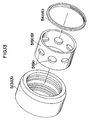
- feeder
- Prior art date
- Legal status (The legal status is an assumption and is not a legal conclusion. Google has not performed a legal analysis and makes no representation as to the accuracy of the status listed.)
- Expired - Lifetime
Links
Images



Classifications
-
- B—PERFORMING OPERATIONS; TRANSPORTING
- B23—MACHINE TOOLS; METAL-WORKING NOT OTHERWISE PROVIDED FOR
- B23Q—DETAILS, COMPONENTS, OR ACCESSORIES FOR MACHINE TOOLS, e.g. ARRANGEMENTS FOR COPYING OR CONTROLLING; MACHINE TOOLS IN GENERAL CHARACTERISED BY THE CONSTRUCTION OF PARTICULAR DETAILS OR COMPONENTS; COMBINATIONS OR ASSOCIATIONS OF METAL-WORKING MACHINES, NOT DIRECTED TO A PARTICULAR RESULT
- B23Q11/00—Accessories fitted to machine tools for keeping tools or parts of the machine in good working condition or for cooling work; Safety devices specially combined with or arranged in, or specially adapted for use in connection with, machine tools
- B23Q11/10—Arrangements for cooling or lubricating tools or work
-
- B—PERFORMING OPERATIONS; TRANSPORTING
- B23—MACHINE TOOLS; METAL-WORKING NOT OTHERWISE PROVIDED FOR
- B23Q—DETAILS, COMPONENTS, OR ACCESSORIES FOR MACHINE TOOLS, e.g. ARRANGEMENTS FOR COPYING OR CONTROLLING; MACHINE TOOLS IN GENERAL CHARACTERISED BY THE CONSTRUCTION OF PARTICULAR DETAILS OR COMPONENTS; COMBINATIONS OR ASSOCIATIONS OF METAL-WORKING MACHINES, NOT DIRECTED TO A PARTICULAR RESULT
- B23Q11/00—Accessories fitted to machine tools for keeping tools or parts of the machine in good working condition or for cooling work; Safety devices specially combined with or arranged in, or specially adapted for use in connection with, machine tools
- B23Q11/10—Arrangements for cooling or lubricating tools or work
- B23Q11/1015—Arrangements for cooling or lubricating tools or work by supplying a cutting liquid through the spindle
- B23Q11/103—Rotary joints specially adapted for feeding the cutting liquid to the spindle
-
- B—PERFORMING OPERATIONS; TRANSPORTING
- B23—MACHINE TOOLS; METAL-WORKING NOT OTHERWISE PROVIDED FOR
- B23Q—DETAILS, COMPONENTS, OR ACCESSORIES FOR MACHINE TOOLS, e.g. ARRANGEMENTS FOR COPYING OR CONTROLLING; MACHINE TOOLS IN GENERAL CHARACTERISED BY THE CONSTRUCTION OF PARTICULAR DETAILS OR COMPONENTS; COMBINATIONS OR ASSOCIATIONS OF METAL-WORKING MACHINES, NOT DIRECTED TO A PARTICULAR RESULT
- B23Q2220/00—Machine tool components
- B23Q2220/008—Rotatable tool holders coupled in parallel to a non rotating accessory
-
- Y—GENERAL TAGGING OF NEW TECHNOLOGICAL DEVELOPMENTS; GENERAL TAGGING OF CROSS-SECTIONAL TECHNOLOGIES SPANNING OVER SEVERAL SECTIONS OF THE IPC; TECHNICAL SUBJECTS COVERED BY FORMER USPC CROSS-REFERENCE ART COLLECTIONS [XRACs] AND DIGESTS
- Y10—TECHNICAL SUBJECTS COVERED BY FORMER USPC
- Y10T—TECHNICAL SUBJECTS COVERED BY FORMER US CLASSIFICATION
- Y10T408/00—Cutting by use of rotating axially moving tool
- Y10T408/44—Cutting by use of rotating axially moving tool with means to apply transient, fluent medium to work or product
- Y10T408/45—Cutting by use of rotating axially moving tool with means to apply transient, fluent medium to work or product including Tool with duct
-
- Y—GENERAL TAGGING OF NEW TECHNOLOGICAL DEVELOPMENTS; GENERAL TAGGING OF CROSS-SECTIONAL TECHNOLOGIES SPANNING OVER SEVERAL SECTIONS OF THE IPC; TECHNICAL SUBJECTS COVERED BY FORMER USPC CROSS-REFERENCE ART COLLECTIONS [XRACs] AND DIGESTS
- Y10—TECHNICAL SUBJECTS COVERED BY FORMER USPC
- Y10T—TECHNICAL SUBJECTS COVERED BY FORMER US CLASSIFICATION
- Y10T409/00—Gear cutting, milling, or planing
- Y10T409/30—Milling
- Y10T409/303976—Milling with means to control temperature or lubricate
- Y10T409/304032—Cutter or work
Definitions
- the present invention relates to a coolant feeder in combination with a tool holder assembly according to the precharacterizing portion of claim 1.
- the rotating cutting tool with an oil hole has features to cool and lubricate the cutting edge by machining the workpiece while injecting coolant fed to the oil hole through the cutting edge and extend the service life of the cutting tools as well as improve the finished work surface.
- the conventional oil feeder in the tool holder of this type has a stationary support member 3 which rotatably supports the rotary shaft 1 as shown in Fig.14 built integral with a coolant passage connector later discussed which can be attached and removed to and from the coolant feeding base on the machine tool side, thereby allowing coolant to flow in the coolant feeding passage for tools formed in the rotary shaft via each coolant passage of the connector thereof and stationary support member 3, and feeds coolant to the oil hole of the tools through the said coolant passage.
- oiltight rings 5 are designed to be intermediately mounted between the two to prevent coolant leakage from the interface.
- the applicant of the present invention designed to intermediately install a replaceable sleeve 4 between both bearings 2, 2 located between the rotary shaft 1 and the stationary support member 3 rotatably supporting the said rotary shaft 1 via a pair of bearings 2, 2, as well as to intermediately support the oiltight ring 5 between the stationary support member 3 and the sleeve 4 as shown in Fig. 15.
- the stationary support member 3 is supported with bearings 2, 2 and at the time it is built integral with the aforementioned coolant passage connector, requiring all these parts to be disassembled when the sleeve 4 is replaced and to be reassembled to the original state when the sleeve 4 is mounted, and again producing a problem of extremely troublesome replacement operation.
- US 4 865 495 describes a fluid inducer for coolant to a rotary cutting tool.
- the main inducer body can be separated from the bearing body.
- coolant can penetrate the bearings and damage them.
- Fig. 1 shows one embodiment of the present invention in which an engagement ring 26 for manipulator and an outwardly tapering shank 27 are formed concentrically on one end of the rotary shaft 10, and on the other end a socket 24 to which cutting tool T with oil holes are formed concentrically.
- the rotary shaft 10 is rotatably supported to the stationary support member 11 via the bearing 25, and to tee cylindrical chamber 11A formed at the radial protruded portion on one side, a coolant coupling device 14 which also serves as a staking mechanism is installed.
- the coolant coupling device 14 comprises an outer sleeve 28 slidably accommodated within the said cylindrical chamber 11A in parallel to the rotary shaft 10 and extruding to the side where the shank 27 is located and an inner sleeve 29 threadingly inserted in the outer sleeve 28, and between the outer end of the outer sleeve 28 and the locknut 30 threadingly inserted into the inner sleeve 29, a positioner plate 31 is fixed.
- a check valve 32 comprising a spring 32a and a ball-form valve element 32b energized to close the coolant intake port 29a by means of the said spring 32a is mounted.
- the said outer sleeve 28 is energized outwardly by a compression coil spring 33, and the said coil spring 33 is interposed between the end surface 34 of the outer sleeve 28 and the bottom of the cylindrical chamber 11A. Because the outer sleeve 28 is pressed out outwardly with the energizing force of this spring 33, under the out-of-use condition (see Fig. 10), the idle end of the positioner plate 31 fits in the latch groove 35 provided in the rotary shaft 10 adjacent to the engagement ring 26 for the manipulator and latches the rotary shaft 10 with the stationary support member 11 in such a manner to prevent relative rotation.
- Fig. 1 shows the in-use condition, in which the stationary support member 11, that is, the coolant coupling device 14, is disengaged from the rotary shaft 10.
- a stationary coolant feeder ring 13 is fitted over the rotary shaft 10 adjacent to the stationary support member 11.
- the mounting sequence is as follows: first, thick-wall ring-shaped No. 1 sleeve 19a is fitted over the rotary shaft 10 and brought in contact with the side surface of the stationary support member 11; then, the collar-shaped No. 2 sleeve 19b is fitted over the rotary shaft 10 and brought in contact with No. 1 sleeve 19a. Under this condition, the stationary coolant feeder ring 13 is fitted over No. 1 sleeve 19a and No. 2 sleeve 19b, and thereafter, No.
- 3 sleeve 19c is fitted over the rotary shaft 10, and finally a nut 41 is screwed into the rotary shaft 10 in such a manner to prevent axial displacement of the stationary coolant feeder ring 13 but only rotatably relative to the rotary shaft 10.
- No. 2 sleeve 19b is directly fixed to the rotary shaft 10 with a screw 19d as required.
- No. 1 to No. 3 sleeves 19a to 19c form a sleeve 19.
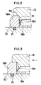
- the stationary coolant feeder ring 13 has a pair of lips 13a, 13a protrudably installed on the inner circumferential surface thereof as shown in Figs. 1-3, and before it is fitted over the rotary shaft 10, the pair of lips 13a, 13a extend outwardly so that intervals they face opposite to each other are widened. Fitting this over the rotary shaft 10 via the sleeve 19 causes the pair of lips 13a, 13a to be held between No. 1 sleeve 19a and No. 3 sleeve 19c of the sleeve 19, bringing the side surfaces of both lips 13a, 13a in close contact with the side surfaces of both No. 1 and No. 3 sleeves 19a, 19c, while the tip ends of both lips 13a, 13a are designed to elastically deform to come in close contact with No. 2 sleeve 19b.
- the stationary coolant feeder ring 13 is formed with hard synthetic resin material such as hard polyacetal resin, vinyl chloride, ABS resin, nylon, tetrafluoro resin, and the like and is designed to bring the side surface and the tip end of a pair of lips 13a, 13a protrudably mounted on the ring inner circumferential surface in close contact with the sleeve 19 to secure oiltightness betwen the two.
- hard synthetic resin material such as hard polyacetal resin, vinyl chloride, ABS resin, nylon, tetrafluoro resin, and the like
- On the inner circumferential surface of the stationary coolant feeder ring 13 an annular groove 17 is formed and with the pressure of the coolant fed to the said annular groove 17, both lips 13a, 13a are deflected toward the side wall of the No. 1 and No. 3 sleeves 19a, 19c as shown with the alternate long and short dash line in Fig. 2 so that oiltightness between the two is further secured.
- the stationary coolant feeder ring 13 may have the portion 13b forming a pair of lips 13a, 13a built separately from the ring proper 13c as shown in Fig. 1a.
- the ring proper 13c may be made from steel or iron and the portion 13b forming a pair of lips 13a, 13a to be mounted to the ring proper may be made from the aforementioned hard synthetic resin.
- the annular groove 17 communicates freely with a radial coolant passage 12 provided on the rotary shaft 10 via a bore 19e provided in the No. 2 sleeve 19b, and on the side of the stationary coolant ring 13 in contact with the above-mentioned coolant coupling device 14, a coolant pipe 15 is protrudably mounted in the radial direction, the tip end of which is connected to the connecting hole 45 provided on the cylindrical chamber 11A of the coolant coupling device 14.
- the stationary coolant ring 13 is kept stationary by connecting the coolant pipe 15 to the coolant coupling device 14, thereby restricting the stationary coolant ring 13 with the coolant coupling device 14, and preventing the rotation.
- the cylindrical chamber 11A consequently, the coolant coupling device 14, is formed separately from the stationary support member 11,and both are designed to be coupled integral with bolts 49, 49. Consequently, in disassembling the stationary coolant feeding ring 13 from the rotary shaft 10, removing the nut 41 arresting the stationary coolant feeding ring 13 and untightening the bolts 49 coupling the coolant coupling device 14 to the stationary support member 11 enables the coolant coupling device 13 to be removed from the stationary support member 11 together with the coolant pipe 15 and the stationary coolant feeding ring 13 to be easily pulled out from the rotary shaft 11 together with the No. 3 sleeve 19c.
- Arranging the stationary coolant feeding ring 13 axially adjacent to the stationary support member 11 eliminates the necessity to disassemble the stationary support member 11 pivoted by bearings 25, 25 from the rotary shaft 10, enabling quick disassembly operation as much.
- Coolant does not leak from the clearance between the No. 1 sleeve 19a and stationary coolant feeding ring 13 but even if coolant should leak unexpectedly,since a large gap 22 is provided between the stationary coolant feeding ring 13 and stationary support member 11, the leakage coolant is discharged outside from the said gap 22 and does not enter the stationary support member 11 side.
- the stationary coolant feeding ring 113 is fitted over the rotary shaft 10 adjacent to the stationary support member 11, both ends of which are latched to the rotary shaft 10 with snap rings 141, 141 and mounted rotatably only relative to the rotary shaft 10.
- an annular groove 17 is formed and with the said annular groove 17 inbetween, on the inner circumferential surface of the stationary coolant feeding ring 13, the thread 40 is formed.
- This thread 40 prevents as much as possible the coolant from leaking to the stationary support member 11 side by restricting the coolant with the thread 40 through frictional action between the said thread 40 and the coolant when the coolant tries to leak to the outside from the clearance between the stationary coolant feeding ring 113 and the rotary shaft 10. If ever the coolant should leak outside unexpectedly, the leakage coolant can be discharged outside from the drain 122 between the stationary support member 11 and stationary coolant feeding ring 113.
- numeral 36 is a wear plate which protects bearing 25.
- a passage 222 for drainage which is in communication with the outside may be located between the stationary support member 211 and stationary coolant feeding ring 213 and be provided on the stationary coolant feeding ring 213 itself.
- the stationary coolant feeding ring 213 may be designed to come in contact with the stationary support member 211 or the stationary coolant feeding ring 213 may be designed to be built integral with the stationary support member 211.
- the aforementioned embodiment indicates the case where the stationary coolant feeding ring 13 is independently installed separately from the stationary support member 11 but the stationary support member 311 may be designed to be built integral with the stationary coolant feeding ring 313 as shown in Fig. 8. That is, the stationary support member 311 may be extended in the axial direction, on the inner circumferential side of the said extended portion 311a a stationary coolant feeding ring member 313a is mounted and with the snap rings 341, 341, 341 mounted to the extended side and the rotary shaft side, the stationary coolant feeding ring member 313a is installed in such a manner to prevent axial displacement but to enable rotation only relative to the rotary shaft 10.
- the material of the two may be changed to reduce friction between the two as much as possible, for example, the material of the stationary coolant feeding ring 13 may be formed with gun metal or hard resin material as against the steel used for the material ofthe rotary shaft 10, and hard synthetic resin material is desirable as described above particularly from viewpoint of processing or fabrication unit costs.
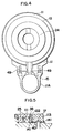
- the oiltight ring 420 may also be allowed to intervene on the inner circumferential surface of the stationary coolant feeding ring 413 as shown in Fig. 9. In Fig. 8 also, though it is not illustrated, the oiltight ring may be allowed to intervene on the inner circumferential surface of the stationary coolant feeding ring member 313a.
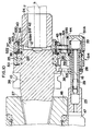
- Fig. 10 shows another embodiment, and while the embodiment shown in Fig. 1 indicates the in-use condition in which the coolant coupling device 14 is latched to the coolant feeding base 23, Fig. 10 shows the condition where the coolant coupling device 514 is released from the coolant feeding base 23. Consequently, the idle end of the positioner plate 531 fits in the dent groove 35 provided in the rotary shaft 10 adjacent to the engagement ring 26 and latches the rotary shaft 10 and stationary support member 11 in such a manner to prevent relative rotation.
- the sleeve 519 is allowed to intervene between the stationary coolant feeding ring 513 and rotary shaft 10, and the sleeve 519 is fixed to the rotary shaft 10 with a lock nut 541. That is, an annular groove 17 is provided on the inner circumferential surface of the stationary coolant feeding ring 513 and at the same time to the sleeve 519 a coolant passage 519a in communication with the said annular groove 17 is formed, and with these annular groove 17 and coolant passage 519a located inbetween, a pair of oiltight rings 520 in contact with the outer circumferential surface of the sleeve 519 is mounted on the inner circumferential surface of the stationary coolant feeding ring 513.
- the coolant pipe 515 protrudably mounted to the stationary coolant feeding ring 513 is energized with the spring 43 to protrudably move as well as to retract against the energizing force of the spring 43.
- the coolant pipe is protruded by being energized with the spring 43, it is designed to connect with the hollow 16 of the coolant coupling device.
- the sleeve 519 is desirable to be formed with a regular steel plate on which chromium is plated, a combination of hardened steel and cemented carbide, or the materials thereof coated with ceramics or titanniterite, or any other material whose surface possesses the wear resistance.
- a sub-oiltight ring 521 is mounted closely in contact with the rotary shaft 10 and between the stationary coolant feeding ring 513 and sleeve 519 as well as stationary support member 11, a wear plate 36 and sliding contact plate 37 are interposed.
- an engagement protrusion 38 is formed (shown a little closer to the bottom in Fig. 10), and the said protrusion 38 is designed to latch with the latching dent 39 formed in the stationary coolant feeding ring 513. Consequently, the stationary coolant feeding ring 513 is latched to the stationary support member 511 and is held stationary.
- Other configuration is the same as that of the embodiment shown in Fig. 1, and therefore the explanation is omitted by assigning the same symbol to each component member as that in Fig. 1.
- the oiltight ring 520 is interposed between the stationary coolant feeding ring 513 and the sleeve 519 and the sub-oiltight ring 521 is interposed between the sleeve 519 and the rotary shaft 10, but they may be brought directly in contact with each other without interposing the oiltight ring.
- the material of the two should be changed, for example, the material of the stationary coolant feeding ring 613 is formed with gun metal or hard resin material, while the sleeve 619 should be formed with either iron or steel.
- Numeral 621 is the sub-oiltight ring.
- Other configuration is the same as that of the embodiment shown in Fig. 10, and therefore the explanation is omitted by assigning the same symbol to each component member as that in Fig. 10.
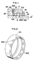
- a drain hole 522 as clearly shown in Fig. 12 is formed at proper intervals on the outer circumferential surface and the drain hole is arranged at the boundary between the stationary support member 511 and the stationary coolant feeding ring 513 as shown in Fig. 10.
- a slide contact plate 40 also is mounted in contact with the tip end side of the stationary coolant feeding ring 513 and under this condition, a nut 41 is screwed into the thread 42 provided on the outer circumferential surface of the rotary shaft 10 to prevent axial displacement of the sleeve 519 and stationary coolant feeding ring 513 as well as to enable the sleeve 519 to rotate together with the rotary shaft 10.
- the coolant coupling device 14 which also serves to lock the stationary support member 11 is latched to the coolant feeding base 23 provided at the fixed portion 47 of the machine tool (Fig. 1); then, the positioner plate 31 retracts against the energizing force of the coil spring 33 and the engagement between the said member 31 and the dent groove 35 on the rotary shaft 10 side is released, and the rotary shaft 10 is rotatably held. Consequently, with the rotary shaft 10 held to the stationary support member 11, a specified cutting operation takes place with the rotating cutting tool T mounted to the socket 24 at the tip end.
- the coolant delivered from the coolant supply groove of the coolant feeding base pushes open the check valve 32, passes through the hollow 16 of the coolant coupling device 14, the radial passage 18 of the coolant pipe 15, and the annular groove 17 of the stationary coolant feeding ring 13, and with the inner circumferential surface of the said stationary coolant feeding ring 13 brought in direct and oiltight contact with the outer circumferential surface of the rotary shaft to properly maintain oiltightness, or with oiltightness properly held with a pair of oiltight rings 20, 20 at the relative interface between the stationary coolant feeding ring 13 and sleeve 19, is delivered through the radial passage 12 on the roatry shaft 10 side to the oil hole h of the cutting tool T and is discharged from the tip end of the said tool T.
- the stationary coolant feeding ring 13 may move axially while the rotary shaft 10 is on the way of rotating, but as shown in Fig. 2, the displacement of the stationary coolant feeding ring 13 is designed to be prevented with the portions 50, 51 which are in contact with the sleeve 19.
- the coolant pipe 515 is retracted against the energizing force of the spring 43 and the said coolant pipe 515 is separated from the coolant coupling device 514, and under this condition, the nut 14 is removed and, as shown in Fig. 13, either the stationary coolant ring 13, 513 only or the sleeve 19, 519 and the stationay coolant feeding ring 13, 513 located around its outer circumferential side are integrally or separately removed from the socket 24 side, and the sleeve 19, 519 alone or with the worn oiltight ring 20, 520 can be replaced as required.
- mounting the rotary shaft 10 to the spindle 48 of a machine tool and connecting the coolant coupling device 14, 514 which supports the stationary support member 11 (111, 211, 311, 411, 511, 611) free from rotation with the coolant feeding base 23 on the machine tool side enables the rotary shaft 10 to be rotatably pivoted by the said stationary support member 11 and the stationary coolant feeding ring 13 (113, 213, 313, 413, 513, 613) to be supported or latched with the stationary support member 11, or to be supported free from rotation by being restricted with the coolant coupling device 14, 514 via the coolant pipe 15, 515.
- the annular groove 17 of the stationary coolant feeding ring 13 is kept constantly in communication with the radial passage 18 of the coolant pipe 15, 515 as well as the hollow of the coolant coupling device 14, 514 irrespective to rotation of the rotary shaft 10, and consequently connecting the coolant coupling device 14, 514 with the above-mentioned coolant feeding base 23 allows the coolant from the coolant feeding base 23 to flow through the hollow 16 of the coolant coupling device 14, 514, the radial passage for coolant pipe 15, 515, and annular groove 16 of the stationary coolant feeding ring 13, the radial passage 18 of the oil pipe 15, 515, the annular groove 17 of the stationary coolant feeding ring 13 and radial passage 12 of the rotary shaft, then feeds to the oil hole h of the tool T.
- the stationary coolant feeding ring 13 wears over a long time of application, for example, if the stationary coolant feeding ring 13 is formed with hard resin and the inner circumferential surface of the stationary coolant feeding ring 13 in contact with the outer circumferential surface of the rotary shaft 10 wears and oiltightness between the two is slightly lost, the stationary coolant feeding ring alone can be replaced.
- the drain for discharging coolant 22 (122, 222, 322, 422, 522, 622) is interposed, and the coolant leaking from the clearance between the stationary coolant feeding ring 13 and the rotary shaft 10 is discharged outside from the drain 22 before it reaches the bearing 25 of the stationary support member 11 and does not enter the said bearing 25, fully exhibiting the fail-safe capabilities.
- the clearance 22 (122, 222, 322, 422, 522, 622) for drain interposed between the stationary support member 11 and stationary coolant feeding ring 13 serves to discharge outside the coolant leaking from the clearance between the stationary coolant feeding ring 13 and the rotary shaft 10 before the coolant reaches the bearing of the stationary support member 11 and prevents the coolant from entering the said bearing 25, enabling the fail-safe capabilities to be exhibited to its maximum, and at the same time because the stationary coolant feeding ring 13 is built separately from the stationary support member 11, the material of the stationary coolant feeding ring 13 can be changed from that of the stationary support member 11 and can be optionally selected, for example, it can be formed with hard synthetic resin or material different from the rotary shaft 10 such as gun metal.
- the removable sleeve 19, 519 is interposed between the stationary coolant feeding ring 13 and the rotary shaft 10, if the sleeve 19, 519 wears during the long-period application, the said sleeve only may be removed from the rotary shaft 10 and replaced with a new sleeve.
- both lips 13a, 13a are elastically deformed with the pressure of the coolant fed to the inner circumferential surface side of the stationary coolant feeding ring 13 and brought more strongly in contact with the sleeve 19,thereby further improving oiltightness between the two.
- the drain passage 222 which is located between the stationary support member 211 and stationary coolant feeding ring 213 and is in communication with the outside is provided inside the stationary coolant feeding ring 213 serves to discharge outside the coolant leaking from the clearance between the stationary-coolant feeding ring 213 and the rotary shaft 10 before the coolant reaches the bearing of the stationary support member 211 and prevents the coolant from entering the said bearing 25, enabling the fail-safe capabilities to be exhibted to its maximum.
- the stationary coolant feeding ring 13, 113, 213, 413, 513, 613 built separately from the stationary support member 11, 111, 211, 411, 511, 611 is formed with hard synthetic resin or gun metal, it can be easily machined and fabricated at low costs, and because it is possible to select the material with a small frictional coefficient, it can be used stably over a comparatively long period of time.
- the drain passage 322 interposed between the stationary support member 11 and stationary coolant feeding ring 313 serves to discharge outside the coolant leaking from the clearance between the stationary coolant feeding ring 313 and the rotary shaft 10 before the coolant reaches the bearing 25 of the stationary support member 311 and prevents the coolant from entering the said bearing 25, enabling the fail-safe capabilities to be exhibited to its maximum, and at the same time, because the stationary coolant feeding ring 313 is built integral with the stationary support member 313, the stationary coolant ring 313 is securely supported by the stationary support member 311 and achieves a simple construction.
- the said stationary coolant feeding ring 313 comprises an outside cover 311a formed integral with the stationary support member 311 and a stationary coolant feeding ring member 313a which is independent from the said outside cover 311a but supported on the inner side, when the stationary coolant feeding ring member 313a directly in contact with the rotary shaft 10 wears, it is not required to replace the whole stationary coolant feeding ring 313 but only the stationary coolant feeding ring member 313a is replaced, resulting in low costs.
- the said stationary coolant feeding ring member 313a is made from hard synthetic resin or gun meal, it is easy to be machined and fabricated at low costs, and because the material with a small frictional coefficient, it can be used stably over a comparatively long period of time.
- the stationary coolant feeding ring 13, 513 when the inner circumferential surface of the stationary coolant feeding ring 13, 513 wears due to cutting chips, etc. which enter between the outer circumferential surface of the rotary shaft 10 and the inner circumferential surface of the stationary coolant feeding ring 13, 513 after the application over a long period of time, resulting in a dent, losing oiltightness between the two, and requiring replacement of the stationary coolant feeding ring 13, 513, with the replaceable coolant pipe 15, 515 released from either the stationary coolant feeding ring 13, 513 or the coolant coupling device 14, 514, the stationary coolant feeding ring 13, 513 should be moved along the outer circumferential surface of the rotary shaft 10 and removed from the socket 24 side.
- the sleeve 19, 519 when the outer circumferential surface of the sleeve 19, 519 wears due to cutting chips, etc. which enter between the outer circumferential surface of the sleeve 19, 519 and the inner circumferential surface of the stationary coolant feeding ring 13, 513 after the application over a long period of time, resulting in a dent, losing oiltightness between the two, and requiring replacement of the sleeve 19, 519, with the replaceable coo!ant pipe 15, 515 released from the coolant coupling device 14, 514, the sleeve 19, 519 should be moved along the outer circumferential surface of the rotary shaft 10 together with the stationary coolant feeding ring 13, 513 and removed from the socket 24 side.
- the renewed sleeve 19, 519 is again mounted to the outer circumferential surface of the rotary shaft 10 together with the stationary coolant feeding ring 13, 513 and the coolant pipe 15, 515 is connected with the coolant coupling device 14, 514, and with this operation, a series of the coolant feeding passage is formed.
- the tool holder assembly is formed by interposing the oiltight ring 520 between the stationary coolant feeding ring 513 and the sleeve 519, securing good oiltightness between the two.
- the tool holder assembly is formed by interposing the sub-oiltight ring 21, 521 between the sleeve 19, 519 and the rotary shaft 10, securely peventing an entry of coolant to the bearing 25 side.
- the tool holder assembly is formed by providing the threads 40, 40 on the inner circumferential surface of the stationary coolant feeding ring 113, with the annular groove 17 provided on the said inner circumferential surface in between, and on both sides thereof, the coolant is restricted by the thread 40 by frictional action between the said thread 40 and the coolant when the coolant tries to leak outside from the clearance between the stationary coolant feeding ring 113 and the rotary shaft 10 on the way of rotation of the rotary shaft 10; this prevents the leakage as much as possible and exhibits the action to push back the coolant to the annular groove 17. That is, the said thread 40 is formed in the direction which pushes back the coolant leaking from the outer circumferential surface thereof during the rotation of the rotary shaft 10 toward the annular groove 17 side.
- the stationary support member 11, 511 is integrally built with the coolant coupling device 14, 514 which can be connected to the coolant feeding base 23 provided on the machine tool side, and is equipped with a positioner plate 31, 531 to prevent relative rotation of the coolant coupling device 14, 514 and the rotary shaft 10 by allowing the two to check each other when the said coolant coupling device 14, 514 is not connected with the coolant feeding base 23 as well as relases the checking condition between the coolant coupling device 14, 514 and the rotary shaft 10 and enables rotation of the rotary shaft 10 when the coolant coupling device 14, 514 is connected with the coolant feeding base 23, and, therefore, the stationary support member 11, 511 and the coolant coupling device 14, 51 integral therewith are transported from the spindle 48 to magazines free of oscillation and are accurately placed in magazines under the fixed condition integral with the rotary shaft 10 when they are released from the spindle 48 on the machine tool side.
Landscapes
- Engineering & Computer Science (AREA)
- Mechanical Engineering (AREA)
- Auxiliary Devices For Machine Tools (AREA)
- Sealing Devices (AREA)
- Joints Allowing Movement (AREA)
Claims (17)
- Distributeur d'agent de refroidissement en combinaison avec un agencement de porte-outil, qui comprend un axe de rotation (10) monté sur la broche d'une machine-outil, dans lequel une bague stationnaire d'alimentation en agent de refroidissement (13; 113; 213; 413; 513; 613) présente une rainure annulaire (17) sur sa face intérieure, de façon à communiquer avec un passage radial (12) prévu dans l'axe de rotation (10), pour délivrer un agent de refroidissement à un outil devant être maintenu dans l'axe de rotation, et la bague stationnaire d'alimentation en agent de refroidissement (13) est connectée du côté machine-outil à un conduit pour agent de refroidissement (15; 515), caractérisé en ce qu'un organe de support stationnaire (11; 111; 211; 311; 411; 511; 611) supporte à rotation le dit axe de rotation (10), et la bague stationnaire d'alimentation en agent de refroidissement (13; 113; 213; 413; 513; 613) est ajustée sur l'axe de rotation (10), de manière contigue au dit organe de support stationnaire (11), et un dispositif de couplage (14; 514) pour agent de refroidissement est connecté du côté machine-outil au conduit pour agent de refroidissement (15; 515) de sorte qu'un creux de passage d'agent de refroidissement (16) à l'intérieur du dit dispositif de couplage pour agent de refroidissement (14; 514) peut entrer en communication avec la rainure annulaire (17) de la bague stationnaire d'alimentation en agent de refroidissement (13; 513) par l'intermédiaire d'un passage interne (18) du dit conduit pour agent de refroidissement (15; 515), et un drain (22; 122; 222; 322; 422; 522; 622) est interposé entre l'organe de support stationnaire (11) et la bague stationnaire pour agent de refroidissement (13).
- Distributeur d'agent de refroidissement en combinaison avec un agencement de porte-outil selon la revendication 1, dans lequel l'organe de support stationnaire (11) et la bague stationnaire d'alimentation en agent de refroidissement (13) sont montés séparément, et le dit drain (22) est formé par un espace libre (22) interposé entre eux.
- Distributeur d'agent de refroidissement en combinaison avec un agencement de porte-outil selon la revendication 1, dans lequel un manchon amovible (19) est interposé entre la dite bague stationnaire d'alimentation en agent de refroidissement (13) et l'axe de rotation (10).
- Distributeur d'agent de refroidissement en combinaison avec un agencement de porte-outil selon la revendication 3, dans lequel une paire de lèvres (13a, 13a) font saillie sur la surface circonférentielle intérieure de la dite bague stationnaire d'alimentation en agent de refroidissement (13), et les deux lèvres (13a, 13a) sont amenées en contact étroit avec le dit manchon (19).
- Distributeur d'agent de refroidissement en combinaison avec un agencement de porte-outil selon la revendication 2, dans lequel le dit drain (22) est formé par un orifice de drain (222) qui relie l'intérieur de la bague d'alimentation en agent de refroidissement (213) à l'extérieur de celle-ci.
- Distributeur d'agent de refroidissement en combinaison avec un agencement de porte-outil selon la revendication 2, dans lequel la dite bague d'alimentation en agent de refroidissement (13, 113, 213, 413, 513, 613) est constituée d'une résine synthétique dure ou d'un métal pour arme à feu.
- Distributeur d'agent de refroidissement en combinaison avec un agencement de porte-outil selon la revendication 1, dans lequel l'organe de support stationnaire (311) est construit d'une pièce avec la bague stationnaire d'alimentation en agent de refroidissement (313), et le dit drain (22) est un passage (322) prévu entre eux.
- Distributeur d'agent de refroidissement en combinaison avec un agencement de porte-outil selon la revendication 7, dans lequel la dite bague stationnaire d'alimentation en agent de refroidissement (313) comprend une enveloppe extérieure (311a) formée d'une pièce avec l'organe de support stationnaire (311), et un organe annulaire d'alimentation en agent de refroidissement (313a) lequel est différent de la dite enveloppe extérieure (311a).
- Distributeur d'agent de refroidissement en combinaison avec un agencement de porte-outil selon la revendication 8, dans lequel le dit organe annulaire d'alimentation en agent de refroidissement (313a) est constitué d'une résine synthétique dure ou d'un métal pour arme à feu.
- Distributeur d'agent de refroidissement en combinaison avec un agencement de porte-outil selon la revendication 2, dans lequel l'organe de support stationnaire (11, 511) est construit séparément de la bague stationnaire d'alimentation en agent de refroidissement (13, 513), et le conduit pour agent de refroidissement (15, 515) est monté de manière amovible.
- Distributeur d'agent de refroidissement en combinaison avec un agencement de porte-outil selon la revendication 10, dans lequel un manchon amovible (19) est interposé entre la bague stationnaire d'alimentation en agent de refroidissement (13, 513) et l'axe de rotation (10), et le manchon (19, 519) tourne solidairement avec l'axe de rotation (10), et est détachable du dit axe de rotation (10).
- Distributeur d'agent de refroidissement en combinaison avec un agencement de porte-outil selon la revendication 10, dans lequel une bague étanche à l'huile (20, 520) est interposée entre la bague stationnaire d'alimentation en agent de refroidissement (13, 513) et le manchon (19, 519).
- Distributeur d'agent de refroidissement en combinaison avec un agencement de porte-outil selon la revendication 12, dans lequel une bague étanche sous huile (21, 521) est interposée entre le dit manchon (19, 519) et l'axe de rotation (10).
- Distributeur d'agent de refroidissement en combinaison avec un agencement de porte-outil selon la revendication 2, dans lequel des filets (40) sont formés sur la surface circonférentielle intérieure de la bague stationnaire d'alimentation en agent de refroidissement (113) devant et derrière la rainure annulaire (17).
- Distributeur d'agent de refroidissement en combinaison avec un agencement de porte-outil selon la revendication 2, dans lequel la bague stationnaire d'alimentation en agent de refroidissement (13, 513) est soutenue de manière non-rotative sur le dispositif de couplage pour agent de refroidissement (14, 514) du côté machine-outil, par le dit conduit pour agent de refroidissement (15, 515).
- Distributeur d'agent de refroidissement en combinaison avec un agencement de porte-outil selon la revendication 2, dans lequel la bague stationnaire d'alimentation en agent de refroidissement (13, 513) est engagée avec, et soutenue de manière non-rotative sur l'organe de support stationnaire (511) par les moyens d'engagement (38, 39).
- Distributeur d'agent de refroidissement en combinaison avec un agencement de porte-outil selon la revendication 1, dans lequel l'organe de support stationnaire (11, 511) est construit d'une pièce avec le dispositif de couplage pour agent de refroidissement (14, 514) qui est adapté pour être relié à une base d'alimentation en agent de refroidissement (23) prévue du côté machine-outil, et est équipé d'une plaque de positionnement (31, 531) prévue pour empêcher la rotation de l'axe de rotation (10) par rapport au dispositif de couplage pour agent de refroidissement (14, 514) par restriction mutuelle lorsque le dit dispositif de couplage pour agent de refroidissement (14, 514) n'est pas relié à la base d'alimentation en agent de refroidissement (23), de même qu'il libère la restriction mutuelle entre le dispositif de couplage pour agent de refroidissement (14, 514) et l'axe de rotation (10), et permet la rotation de l'axe de rotation (10) relative au dispositif de couplage pour agent de refroidissement lorsque le dispositif de couplage pour agent de refroidissement (14, 514) est connecté à la base d'alimentation en agent de refroidissement (23).
Applications Claiming Priority (6)
| Application Number | Priority Date | Filing Date | Title |
|---|---|---|---|
| JP14785193 | 1993-06-18 | ||
| JP147851/93 | 1993-06-18 | ||
| JP14785193A JPH0825124B2 (ja) | 1993-06-18 | 1993-06-18 | 工具ホルダーにおける給油装置 |
| JP18462793A JPH0829476B2 (ja) | 1993-07-27 | 1993-07-27 | 工具ホルダーにおける給油装置 |
| JP18462793 | 1993-07-27 | ||
| JP184627/93 | 1993-07-27 |
Publications (3)
| Publication Number | Publication Date |
|---|---|
| EP0629462A2 EP0629462A2 (fr) | 1994-12-21 |
| EP0629462A3 EP0629462A3 (fr) | 1995-07-26 |
| EP0629462B1 true EP0629462B1 (fr) | 2000-05-03 |
Family
ID=26478272
Family Applications (1)
| Application Number | Title | Priority Date | Filing Date |
|---|---|---|---|
| EP94100810A Expired - Lifetime EP0629462B1 (fr) | 1993-06-18 | 1994-01-20 | Porte-outil muni d'un approvisionnement d'un réfrigérant |
Country Status (5)
| Country | Link |
|---|---|
| US (1) | US5439333A (fr) |
| EP (1) | EP0629462B1 (fr) |
| KR (1) | KR0124041B1 (fr) |
| CN (1) | CN1096726A (fr) |
| DE (1) | DE69424222T2 (fr) |
Families Citing this family (15)
| Publication number | Priority date | Publication date | Assignee | Title |
|---|---|---|---|---|
| GB9425224D0 (en) * | 1994-12-14 | 1995-02-08 | Bristol Tool Gauge | Adaptor |
| US5601386A (en) * | 1995-01-18 | 1997-02-11 | Mcdonnell Douglas Corporation | Cutter body including cutting fluid gland |
| DE19516986C2 (de) * | 1995-05-09 | 1999-01-07 | Sauter Kg Feinmechanik | Spindelkopf für Werkzeuge |
| JP4809521B2 (ja) * | 2000-09-19 | 2011-11-09 | マンヨーツール株式会社 | 工具ホルダ及びその冷却装置 |
| JP3806312B2 (ja) * | 2001-04-25 | 2006-08-09 | ファナック株式会社 | スピンドルスルークーラントにおける主軸保護構造 |
| ITVI20060293A1 (it) * | 2006-10-03 | 2008-04-04 | Saccardo Elettromeccanica Srl | Dispositivo atto ad addurre un fluido ad un utensile rotante e relativi testa porta utensile, mandarino ed elettromandrino |
| US7563062B1 (en) * | 2009-01-22 | 2009-07-21 | Chin-Chiu Chen | Milling head |
| US8747033B2 (en) * | 2009-09-02 | 2014-06-10 | Lockheed Martin Corporation | Through tool coolant adapter for drilling motor |
| JP5389584B2 (ja) * | 2009-09-24 | 2014-01-15 | 富士重工業株式会社 | 回転切削装置 |
| CN102335835A (zh) * | 2011-07-15 | 2012-02-01 | 天津市宝涞精密机械有限公司 | 多轴齿轮箱内冷刀具冷却液供给系统 |
| US9375816B2 (en) * | 2012-07-11 | 2016-06-28 | Air Turbine Technology, Inc. | Auto changer spindle mounting assembly adapted to drill tap machines |
| FR2997878B1 (fr) * | 2012-11-13 | 2017-12-22 | Mitis | Systeme d'etancheite pour porte-outil |
| JP2015066674A (ja) * | 2013-10-01 | 2015-04-13 | ファナック株式会社 | 工作機械における主軸と工具ホルダーとの装着部構造 |
| CN103769926A (zh) * | 2014-01-10 | 2014-05-07 | 宁波市荣科迈特数控刀具有限公司 | 一种加工中心油路刀柄 |
| CN104015079B (zh) * | 2014-05-27 | 2016-04-06 | 大连理工大学 | 一种液氮内喷式刀柄装置 |
Family Cites Families (7)
| Publication number | Priority date | Publication date | Assignee | Title |
|---|---|---|---|---|
| US2886346A (en) * | 1956-04-30 | 1959-05-12 | William O Nixon | Drill head with hydraulic thrust balancing means |
| CH448687A (it) * | 1967-03-15 | 1967-12-15 | Actis Sergio | Dispositivo porta utensile, specialmente per trapani, con raffreddamento dell'utensile |
| DE8121883U1 (de) * | 1981-07-25 | 1983-01-05 | Komet Stahlhalter- Und Werkzeugfabrik Robert Breuning Gmbh, 7122 Besigheim | Vorrichtung für die Kühlmittelzufuhr zu mit Kühlmittelkanälen versehenen, rotierenden Schneidwerkzeugen für die spanende Metallbearbeitung, insbesondere Bohrwerkzeugen |
| EP0072657B1 (fr) * | 1981-08-17 | 1984-10-31 | Kennametal Erickson U.K. Limited | Dispositif additionnel pour le montage sur une broche d'entraînement d'une machine |
| JPS59171050U (ja) * | 1983-04-28 | 1984-11-15 | 株式会社 溝口鉄工所 | オイルホ−ル付ホルダ− |
| IT1198610B (it) * | 1983-05-24 | 1988-12-21 | Bakuer Italiana Spa | Dispositivo distributore di refrigerante dall'esterno del mandrino di una macchina utensile applicabile su macchine a controllo numerico e centri di lavoro |
| US4865495A (en) * | 1988-07-28 | 1989-09-12 | Energy Exchanger Co. | Fluid inducer |
-
1994
- 1994-01-14 KR KR94000601A patent/KR0124041B1/ko not_active Expired - Fee Related
- 1994-01-20 DE DE69424222T patent/DE69424222T2/de not_active Expired - Lifetime
- 1994-01-20 EP EP94100810A patent/EP0629462B1/fr not_active Expired - Lifetime
- 1994-01-28 CN CN94101091A patent/CN1096726A/zh active Pending
- 1994-02-17 US US08/198,159 patent/US5439333A/en not_active Expired - Lifetime
Also Published As
| Publication number | Publication date |
|---|---|
| DE69424222T2 (de) | 2000-10-26 |
| EP0629462A3 (fr) | 1995-07-26 |
| EP0629462A2 (fr) | 1994-12-21 |
| DE69424222D1 (de) | 2000-06-08 |
| US5439333A (en) | 1995-08-08 |
| CN1096726A (zh) | 1994-12-28 |
| KR0124041B1 (en) | 1997-11-25 |
| KR950000301A (ko) | 1995-01-03 |
Similar Documents
| Publication | Publication Date | Title |
|---|---|---|
| EP0629462B1 (fr) | Porte-outil muni d'un approvisionnement d'un réfrigérant | |
| RU2409451C2 (ru) | Приспособление для крепления инструмента | |
| US5868533A (en) | Finishing tool for precision machining of holes | |
| US5601386A (en) | Cutter body including cutting fluid gland | |
| US7070491B2 (en) | Machine tool with fluid actuated helical adjustment of abrasive elements | |
| US6533509B1 (en) | Tool holder unclamp mechanism for a milling machine | |
| US5651567A (en) | Multi-passage bearingless fluid coupler | |
| US4636118A (en) | Coolant supply extension member in rotating cutting tool | |
| JPH03209089A (ja) | 回転機械部材への流体供給装置 | |
| CA1198299A (fr) | Foret helicoidal | |
| US5181812A (en) | Gun drill mechanism | |
| US4697965A (en) | Apparatus for preventing invasion of cutting liquid in replaceable head type machine tool | |
| US6739949B2 (en) | Adjustable tool body with fluid actuation | |
| EP0199693A2 (fr) | Alimentation en liquide de refroidissement d'un outil de coupe rotatif | |
| US5957017A (en) | Dead center for machine tools | |
| US5716080A (en) | Bearingless fluid coupler | |
| US5277523A (en) | Precision depth spindle | |
| JPH05133491A (ja) | ロータリジヨイント | |
| JPH0333442B2 (fr) | ||
| US2496995A (en) | Guide collet | |
| US4996908A (en) | Through hole rotating cylinder | |
| US4764062A (en) | Coolant supply shank for a rotating cutting tool | |
| JPS59134606A (ja) | 工作機械のボ−リングバ−軸受装置 | |
| JPH07314281A (ja) | 工具ホルダーにおける給油装置 | |
| US5183363A (en) | Non-contact coolant supply apparatus |
Legal Events
| Date | Code | Title | Description |
|---|---|---|---|
| PUAI | Public reference made under article 153(3) epc to a published international application that has entered the european phase |
Free format text: ORIGINAL CODE: 0009012 |
|
| AK | Designated contracting states |
Kind code of ref document: A2 Designated state(s): CH DE FR GB IT LI |
|
| PUAL | Search report despatched |
Free format text: ORIGINAL CODE: 0009013 |
|
| AK | Designated contracting states |
Kind code of ref document: A3 Designated state(s): CH DE FR GB IT LI |
|
| 17P | Request for examination filed |
Effective date: 19950906 |
|
| 17Q | First examination report despatched |
Effective date: 19980330 |
|
| GRAG | Despatch of communication of intention to grant |
Free format text: ORIGINAL CODE: EPIDOS AGRA |
|
| GRAG | Despatch of communication of intention to grant |
Free format text: ORIGINAL CODE: EPIDOS AGRA |
|
| GRAH | Despatch of communication of intention to grant a patent |
Free format text: ORIGINAL CODE: EPIDOS IGRA |
|
| GRAH | Despatch of communication of intention to grant a patent |
Free format text: ORIGINAL CODE: EPIDOS IGRA |
|
| GRAA | (expected) grant |
Free format text: ORIGINAL CODE: 0009210 |
|
| AK | Designated contracting states |
Kind code of ref document: B1 Designated state(s): CH DE FR GB IT LI |
|
| PG25 | Lapsed in a contracting state [announced via postgrant information from national office to epo] |
Ref country code: LI Free format text: LAPSE BECAUSE OF FAILURE TO SUBMIT A TRANSLATION OF THE DESCRIPTION OR TO PAY THE FEE WITHIN THE PRESCRIBED TIME-LIMIT Effective date: 20000503 Ref country code: FR Free format text: LAPSE BECAUSE OF FAILURE TO SUBMIT A TRANSLATION OF THE DESCRIPTION OR TO PAY THE FEE WITHIN THE PRESCRIBED TIME-LIMIT Effective date: 20000503 Ref country code: CH Free format text: LAPSE BECAUSE OF FAILURE TO SUBMIT A TRANSLATION OF THE DESCRIPTION OR TO PAY THE FEE WITHIN THE PRESCRIBED TIME-LIMIT Effective date: 20000503 |
|
| REG | Reference to a national code |
Ref country code: CH Ref legal event code: EP |
|
| REF | Corresponds to: |
Ref document number: 69424222 Country of ref document: DE Date of ref document: 20000608 |
|
| ITF | It: translation for a ep patent filed | ||
| EN | Fr: translation not filed | ||
| REG | Reference to a national code |
Ref country code: CH Ref legal event code: PL |
|
| PG25 | Lapsed in a contracting state [announced via postgrant information from national office to epo] |
Ref country code: GB Free format text: LAPSE BECAUSE OF NON-PAYMENT OF DUE FEES Effective date: 20010120 |
|
| PLBE | No opposition filed within time limit |
Free format text: ORIGINAL CODE: 0009261 |
|
| STAA | Information on the status of an ep patent application or granted ep patent |
Free format text: STATUS: NO OPPOSITION FILED WITHIN TIME LIMIT |
|
| 26N | No opposition filed | ||
| GBPC | Gb: european patent ceased through non-payment of renewal fee |
Effective date: 20010120 |
|
| PGFP | Annual fee paid to national office [announced via postgrant information from national office to epo] |
Ref country code: IT Payment date: 20120126 Year of fee payment: 19 |
|
| PGFP | Annual fee paid to national office [announced via postgrant information from national office to epo] |
Ref country code: DE Payment date: 20130122 Year of fee payment: 20 |
|
| REG | Reference to a national code |
Ref country code: DE Ref legal event code: R071 Ref document number: 69424222 Country of ref document: DE |
|
| PG25 | Lapsed in a contracting state [announced via postgrant information from national office to epo] |
Ref country code: DE Free format text: LAPSE BECAUSE OF EXPIRATION OF PROTECTION Effective date: 20140121 |