EP0199704A1 - Phasenanschnitt-Steuerschaltung für Motoren - Google Patents
Phasenanschnitt-Steuerschaltung für Motoren Download PDFInfo
- Publication number
- EP0199704A1 EP0199704A1 EP86890069A EP86890069A EP0199704A1 EP 0199704 A1 EP0199704 A1 EP 0199704A1 EP 86890069 A EP86890069 A EP 86890069A EP 86890069 A EP86890069 A EP 86890069A EP 0199704 A1 EP0199704 A1 EP 0199704A1
- Authority
- EP
- European Patent Office
- Prior art keywords
- current
- circuit
- controlled
- control circuit
- voltage
- Prior art date
- Legal status (The legal status is an assumption and is not a legal conclusion. Google has not performed a legal analysis and makes no representation as to the accuracy of the status listed.)
- Granted
Links
- 230000000903 blocking effect Effects 0.000 description 1
- 238000011156 evaluation Methods 0.000 description 1
- 230000005669 field effect Effects 0.000 description 1
- 230000000977 initiatory effect Effects 0.000 description 1
- 230000011664 signaling Effects 0.000 description 1
Images
Classifications
-
- H—ELECTRICITY
- H02—GENERATION; CONVERSION OR DISTRIBUTION OF ELECTRIC POWER
- H02P—CONTROL OR REGULATION OF ELECTRIC MOTORS, ELECTRIC GENERATORS OR DYNAMO-ELECTRIC CONVERTERS; CONTROLLING TRANSFORMERS, REACTORS OR CHOKE COILS
- H02P7/00—Arrangements for regulating or controlling the speed or torque of electric DC motors
- H02P7/06—Arrangements for regulating or controlling the speed or torque of electric DC motors for regulating or controlling an individual DC dynamo-electric motor by varying field or armature current
- H02P7/18—Arrangements for regulating or controlling the speed or torque of electric DC motors for regulating or controlling an individual DC dynamo-electric motor by varying field or armature current by master control with auxiliary power
- H02P7/24—Arrangements for regulating or controlling the speed or torque of electric DC motors for regulating or controlling an individual DC dynamo-electric motor by varying field or armature current by master control with auxiliary power using discharge tubes or semiconductor devices
- H02P7/28—Arrangements for regulating or controlling the speed or torque of electric DC motors for regulating or controlling an individual DC dynamo-electric motor by varying field or armature current by master control with auxiliary power using discharge tubes or semiconductor devices using semiconductor devices
- H02P7/285—Arrangements for regulating or controlling the speed or torque of electric DC motors for regulating or controlling an individual DC dynamo-electric motor by varying field or armature current by master control with auxiliary power using discharge tubes or semiconductor devices using semiconductor devices controlling armature supply only
- H02P7/292—Arrangements for regulating or controlling the speed or torque of electric DC motors for regulating or controlling an individual DC dynamo-electric motor by varying field or armature current by master control with auxiliary power using discharge tubes or semiconductor devices using semiconductor devices controlling armature supply only using static converters, e.g. AC to DC
- H02P7/293—Arrangements for regulating or controlling the speed or torque of electric DC motors for regulating or controlling an individual DC dynamo-electric motor by varying field or armature current by master control with auxiliary power using discharge tubes or semiconductor devices using semiconductor devices controlling armature supply only using static converters, e.g. AC to DC using phase control
Definitions
- the invention relates to a phase gating control circuit for motors with a command stage and at least one current transformer which is used to record the actual value of the motor current and which is additionally used to determine the current zero crossing.
- the exact determination of the point in time when the thyristors are de-energized is also necessary when initiating a reversal of the current direction, because part of the thyristors causing the phase gating must be blocked and other, previously blocked thyristors must be released at the right time and the blocking of a thyristor can only take place at zero current.
- the actual current value is determined with the help of current transformers, then it is obvious to also use it to determine the current zero crossing. However, if the quantity representing the actual current value is obtained by rectifying the current transformer secondary voltage, the difficulty arises that the demagnetizing current of the current transformer is also rectified and simulates a current flow during the period until it completely disappears. The time of the zero current crossing can thus not be recorded exactly, which impairs operational reliability.
- the object of the invention is to eliminate this falsification of the instant of the zero current crossing and achieves this in that a direct voltage depicting the actual current value is obtained from the secondary voltage of one or more current transformers by controlled rectification and is fed to a comparator circuit which serves to detect the current zero crossing.
- the controlled rectification on the secondary side of the converter can thus be suspended before the current is reversed by the command stage, whereupon rectification of the demagnetizing current is ruled out and timely signaling of the current zero crossing is ensured.
- a controlled switch is connected directly to each current transformer and a second controlled switch is connected via an inversion element.
- the controlled switches are expediently actuated by the control circuit for the motor current.
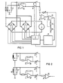
- Fig. 1 of the drawing shows as an embodiment of the invention, the control circuit for a DC motor 1, which is fed from a single-phase network and controlled by phase control.
- a corresponding circuit for operation through a three-phase network is shown in FIG. 2.
- two thyristor-controlled rectifier bridges 2 and 3 are provided for supplying the motor 1 with direct current of both current directions.
- the thyristors of the bridges 2 and 3 are actuated by a control stage 4 as a function of a command stage 5.
- the current for the motor 1 is measured by phase gating using the thyristors of the rectifier bridge 2 or 3 in operation.
- this requires information about the actual value of the motor current, which in the embodiment according to FIG AC circuit switched current converter 6 is obtained, the secondary voltage is tapped at a burden resistor 7.
- the tapped secondary AC voltage is converted by a controlled rectification into a DC voltage which, on the one hand, represents the actual current value for the control stage 4 and, on the other hand, allows the exact time of the zero current crossing to be recorded.
- controlled rectification two controlled switches 8 and 9 are used, the first of which is connected directly to the secondary voltage of converter 6, while switch 9 is connected to one of the inverting inputs of the secondary voltage closed operational amplifier 10 existing inversion element is connected.
- the contacts 8 and 9 are closed by the control stage 4 alternately in time with the frequency of the supplying alternating current, so that they each switch the voltage on only one polarity. 11 with a control stage 4 belonging locking stage is designated, which prevents the two contacts 8 and 9 are never closed at the same time.
- the DC voltage obtained by the controlled rectification by means of contacts 8 and 9 is fed to the input of an impedance converter 12, which consists of a feedback operational amplifier. From the output of the impedance converter 12, the DC voltage representing the actual current is taken and fed to the control stage 4.
- the output of the impedance converter 12 leads to a further operational amplifier 13, which serves as a comparator and whose non-inverting input is connected to the center tap of a voltage divider 14, 15, with the aid of which the point of use of the operational amplifier 13 is determined.
- a pulse is emitted from the output of the operational amplifier 13 at each current zero crossing, which is sent to the command stage 5 for further evaluation in the event of a reversal of the current direction.
- Fig. 2 shows the circuit for the controlled rectification of the secondary voltages of two current transformers 6, 6 ', which are connected on the primary side in two phases of a three-phase network feeding the motor and whose secondary voltages are tapped at the associated load resistors 7, 7'.
- a controlled switch 8 or 8 ' is directly connected to each current transformer 6, 6' and a second controlled switch 9 or 9 'is connected via an inversion element 10 or 10'.
- the voltages switched through by the switches 8, 8 ', 9 and 9' are fed to an impedance converter 12 with a downstream comparator which, in an analogous manner, characterizes the current zero crossing with an output pulse.
- an electronic locking circuit is to be provided, analogous to circuit 11 in FIG. 1, which is constructed from four flip-flops and ensures that only one of switches 8, 8 ', 9 and 9' can be switched on at the same time.
Landscapes
- Engineering & Computer Science (AREA)
- Power Engineering (AREA)
- Control Of Multiple Motors (AREA)
- Control Of Motors That Do Not Use Commutators (AREA)
- Control Of Electric Motors In General (AREA)
- Motor And Converter Starters (AREA)
- Control Of Direct Current Motors (AREA)
- Control Of Stepping Motors (AREA)
- Power Conversion In General (AREA)
Abstract
Description
- Gegenstand der Erfindung ist eine Phasenanschnitt-Steuerschaltung für Motoren mit einer Kommandostufe und mindestens einem der Istwerterfassung des Motorstromes dienenden Stromwandler, der zusätszlich zur Ermittlung des Stromnulldurchganges herangezogen ist.
- Bekanntlich ist zur Steuerung von Gleichstrommotoren die Kenntnis des Istwertes des Motorstromes erforderlich, da der Steuerung eine automatische Stromregelung untergeordnet ist. Bei Gleichstrommotoren, die aus einem Wechselstromnetz mit einem durch Phasenanschnitt gewonnenen Strom gespeist werden, ist es üblich, Stromwandler vorzusehen, die primärseitig in den speisenden Wechselstromkreis eingeschaltet sind und aus deren Sekundärspannung mittels einer Gleichrichterschaltung eine den Stromistwert abbildende Größe gewonnen wird.
- Für die Steuerung ist jedoch bei der Einleitung einer Stromrichtungsumkehr auch die genaue Ermittlung des Zeitpunktes der Stromlosigkeit der Thyristoren erforderlich, denn hierbei muß ein Teil der den Phasenanschnitt bewirkenden Thyristoren gesperrt und zum richtigen Zeitpunkt müssen andere, bisher gesperrte Thyristoren freigegeben werden und die Sperrung eines Thyristors kann erst beim Strom Null erfolgen.
- Wenn der Stromistwert mit Hilfe von Stromwandlern ermittelt wird, dann ist es naheliegend, mit deren Hilfe auch den Stromnulldurchgang festzustellen. Hierbei ergibt sich jedoch, wenn die den Stromistwert abbildende Größe durch Gleichrichtung der Stromwandler-Sekundärspannung gewonnen wird, die Schwierigkeit, daß auch der Abmagnetisierungsstrom des Stromwandlers gleichgerichtet wird und während der Zeitspanne bis zu seinem völligen Verschwinden einen Stromfluß vortäuscht. Es kann somit der Zeitpunkt des Stromnulldurchganges nicht exakt erfaßt werden, was die Betriebssicherheit beeinträchtigt.
- Die Erfindung hat sich die Aufgabe gestellt, diese Verfälschung des Zeitpunktes des Stromnulldurchganges zu beseitigen und erzielt dies dadurch, daß eine den Stromistwert abbildende Gleichspannung aus der Sekundärspannung eines oder mehrerer Stromwandler durch gesteuerte Gleichrichtung gewonnen und einer der Stromnulldurchgangserfassung dienenden Komparatorschaltung zugeführt ist. Die gesteuerte Gleichrichtung auf der Sekundärseite des Wandlers kann somit vor einer Stromumkehr von der Kommandostufe ausgesetzt werden, worauf eine Gleichrichtung des Abmagnetisierungsstromes ausgeschlossen ist und die zeitgerechte Signalisierung des Stromnulldurchganges gewährleistet ist.
- Zur Ableitung der Sekundärspannung ist nach einem weiteren Merkmal der Erfindung an jeden Stromwandler je ein gesteuerter Schalter unmittelbar und je ein zweiter gesteuerter Schalter über je ein Inversionsglied angeschlossen. Hierbei sind die gesteuerten Schalter zweckmäßig von der Steuerschaltung für den Motorstrom betätigt.
- Für die Sicherheit des Betriebes der Steuerschaltung ist es wesentlich, daß jene Schalter, beispielsweise Feldeffekttransistoren, die nacheinander betätigt werden, gehindert sind, daß ihre Schaltzeiten einander übergreifen. Diese Sicherheit ist dann gegeben, wenn nach einem weiteren Merkmal der Erfindung alle gesteuerten Schalter mittels einer elektronischen Verriegelungsschaltung gegen Mehrfacheinschaltungen gesichert sind.
- Fig. 1 der Zeichnung zeigt als Ausführungsbeispiel der Erfindung die Steuerschaltung für einen Gleichstrommotor 1, der aus einem Einphasennetz gespeist und durch Phasenanschnitt gesteuert wird. Eine entsprechende Schaltung für den Betrieb durch ein Dreiphasennetz ist in Fig. 2 dargestellt.
- Bei der Ausführung nach Fig. 1 sind zur Speisung des Motors 1 mit Gleichstrom beider Stromrichtungen zwei thyristorgesteuerte Gleichrichterbrücken 2 und 3 vorgesehen. Die Thyristoren der Brücken 2 und 3 werden durch eine Steuerstufe 4 in Abhängigkeit von einer Kommandostufe 5 betätigt. Die Bemessung des Stromes für den Motor 1 erfolgt durch Phasenanschnitt mittels der Thyristoren der jeweils in Betrieb befindlichen Gleichrichterbrücke 2 oder 3. Hierzu ist jedoch eine Information über den jeweiligen Istwert des Motorstromes erforderlich, die bei der Ausführung nach Fig. 1 mittels eines in den speisenden Wechselstromkreis eingeschalteten Stromwandlers 6 gewonnen wird, dessen Sekundärspannung an einem Bürdenwiderstand 7 abgegriffen wird. Die abgegriffene Sekundär-Wechselspannung wird durch eine gesteuerte Gleichrichtung in eine Gleichspannung gewandelt, die einerseits für die Steuerstufe 4 den Stromistwert abbildet und anderseits den Zeitpunkt des Stromnulldurchganges exakt zu erfassen gestattet. Zur gesteuerten Gleichrichtung dienen zwei gesteuerte Schalter 8 und 9, von denen der erste unmittelbar an die Sekundärspannung des Wandlers 6 angeschlossen ist, während der Schalter 9 an ein aus einem mit seinem invertierenden Eingang an die Sekundärspannung angeschlossenen Operationsverstärker 10 bestehendes Inversionsglied angeschlossen ist. Die Kontakte 8 und 9 werden von der Steuerstufe 4 abwechselnd im Takt der Frequenz des speisenden Wechselstromes geschlossen, so daß sie jeweils die Spannung nur einer Polarität weiterschalten. Mit 11 ist eine der Steuerstufe 4 angehörende Verriegelungsstufe bezeichnet, die verhindert, daß die beiden Kontakte 8 und 9 niemals gleichzeitig geschlossen sind. Die durch die gesteuerte Gleichrichtung mittels der Kontakte 8 und 9 gewonnene Gleichspannung ist dem Eingang eines Impedanzwandlers 12 zugeführt, der aus einem rückgekoppelten Operationsverstärker besteht. Vom Ausgang des lmpedanzwandlers 12 wird die den Stromistwird abbildende Gleichspannung abgenommen und der Steuerstufe 4 zugeführt. Der Ausgang des Impedanzwandlers 12 führt zu einem weiteren Operationsverstärker 13, der als Komparator dient und dessen nichtinvertierender Eingang an den Mittenabgriff eines Spannungsteilers 14, 15 geschaltet ist, mit dessen Hilfe der Einsatzpunkt des Operationsverstärkers 13 festgelegt wird. Vom Ausgang des Operationsverstärkers 13 wird bei jedem Stromnulldurchgang ein Impuls abgegeben, der der Kommandostufe 5 zur weiteren Auswertung im Falle einer Stromrichtungsumnkehr zugeleitet wird.
- Fig. 2 zeigt die Schaltung zur gesteuerten Gleichrichtung der Sekundärspannungen zweier Stromwandler 6, 6' , die primärseitig in zwei Phasen eines den Motor speisenden Drehstromnetzes geschaltet sind und deren Sekundärspannungen an den zugeordneten Bürdenwiderständen 7, 7' abgegriffen werden. Auch hier ist an jeden Stromwandler 6, 6' je ein gesteuerter Schalter 8 bzw. 8' unmittelbar und je ein zweiter gesteuerter Schalter 9 bzw. 9' über je ein Inversionsglied 10 bzw. 10' angeschlossen. Ebenso wie bei der Ausführung nach Fig. 1 werden die von den Schaltern 8, 8', 9 und 9' durchgeschalteten Spannungen einem Impedanzwandler 12 mit nachgeschaltetem Komparator zugeführt, der in analoger Weise den Stromnulldurchgang mit einem Ausgangsimpuls kennzeichnet. Auch bei dieser Schaltung ist analog zur Schaltung 11 der Fig. 1 eine elektronische Verriegelungsschaltung vorzusehen, die aus vier Kippstufen aufgebaut ist und gewährleistet, daß von den Schaltern 8, 8', 9 und 9' gleichzeitig jeweils nur einer eingeschaltet sein kann.
-
- 1 = Gleichstrommotor
- 2,3 = thyristorgesteuerte Gleichrich-
- terbrücken
- 4 = Steuerstufe
- 5 = Kommandostufe
- 6 = Stromwandler
- 7 = Bürdenwiderstand
- 8,9 = gesteuerte Schalter
- 10 = Operationsverstärker
- 11 = Verriegelungsstufe
- 12 = Impedanzwandler
- 13 = Operationsverstärker
- 14,15 Spannungsteiler
Claims (4)
Applications Claiming Priority (2)
| Application Number | Priority Date | Filing Date | Title |
|---|---|---|---|
| AT0114785A AT386706B (de) | 1985-04-16 | 1985-04-16 | Phasenanschnitt-steuerschaltung fuer motoren |
| AT1147/85 | 1985-04-16 |
Publications (2)
| Publication Number | Publication Date |
|---|---|
| EP0199704A1 true EP0199704A1 (de) | 1986-10-29 |
| EP0199704B1 EP0199704B1 (de) | 1990-02-28 |
Family
ID=3507620
Family Applications (1)
| Application Number | Title | Priority Date | Filing Date |
|---|---|---|---|
| EP86890069A Expired - Lifetime EP0199704B1 (de) | 1985-04-16 | 1986-03-20 | Phasenanschnitt-Steuerschaltung für Motoren |
Country Status (3)
| Country | Link |
|---|---|
| EP (1) | EP0199704B1 (de) |
| AT (2) | AT386706B (de) |
| DE (1) | DE3669243D1 (de) |
Families Citing this family (1)
| Publication number | Priority date | Publication date | Assignee | Title |
|---|---|---|---|---|
| AT397880B (de) * | 1991-01-24 | 1994-07-25 | Siemens Ag Oesterreich | Stromerfassungseinrichtung für die steuerung und regelung von umkehrstromrichtern |
Citations (2)
| Publication number | Priority date | Publication date | Assignee | Title |
|---|---|---|---|---|
| DE1516172A1 (de) * | 1963-02-26 | 1970-11-26 | Siemens Ag | Einrichtung zur Signalisierung des Nulldurchganges eines Stromes |
| DE3039282A1 (de) * | 1980-10-17 | 1982-05-19 | Siemens AG, 1000 Berlin und 8000 München | Einrichtung zur nullstromerfassung bei umkehrstromrichtern |
Family Cites Families (2)
| Publication number | Priority date | Publication date | Assignee | Title |
|---|---|---|---|---|
| JPS57138891A (en) * | 1981-02-20 | 1982-08-27 | Fuji Electric Co Ltd | Speed control system for motor |
| DE3230206A1 (de) * | 1982-08-13 | 1984-02-23 | Siemens AG, 1000 Berlin und 8000 München | Regeleinrichtung fuer stromrichter |
-
1985
- 1985-04-16 AT AT0114785A patent/AT386706B/de not_active IP Right Cessation
-
1986
- 1986-03-20 AT AT86890069T patent/ATE50671T1/de not_active IP Right Cessation
- 1986-03-20 EP EP86890069A patent/EP0199704B1/de not_active Expired - Lifetime
- 1986-03-20 DE DE8686890069T patent/DE3669243D1/de not_active Expired - Lifetime
Patent Citations (2)
| Publication number | Priority date | Publication date | Assignee | Title |
|---|---|---|---|---|
| DE1516172A1 (de) * | 1963-02-26 | 1970-11-26 | Siemens Ag | Einrichtung zur Signalisierung des Nulldurchganges eines Stromes |
| DE3039282A1 (de) * | 1980-10-17 | 1982-05-19 | Siemens AG, 1000 Berlin und 8000 München | Einrichtung zur nullstromerfassung bei umkehrstromrichtern |
Also Published As
| Publication number | Publication date |
|---|---|
| DE3669243D1 (de) | 1990-04-05 |
| EP0199704B1 (de) | 1990-02-28 |
| ATE50671T1 (de) | 1990-03-15 |
| AT386706B (de) | 1988-10-10 |
| ATA114785A (de) | 1988-02-15 |
Similar Documents
| Publication | Publication Date | Title |
|---|---|---|
| EP0453518B1 (de) | Stromwandleranordnung für dreileiter-drehstromsysteme, insbesondere zur stromistwerterfassung für geregelte, stromrichtergespeiste gleichstromverbraucher | |
| EP0199704B1 (de) | Phasenanschnitt-Steuerschaltung für Motoren | |
| EP0585703A2 (de) | Verfahren und Einrichtung zur Messung elektrischer Grössen, insbesondere des Stroms, an einem frequenzumformergesteuerten Elektromotor | |
| DE2841856B2 (de) | Schaltungsanordnung zur Erfassung des Stromistwertes von Stromrichtern in Drehstrombriickenschaltung | |
| EP0631145A2 (de) | Verfahren und Vorrichtung zur Strommessung in Brückenschaltungen | |
| DE2457807A1 (de) | Einrichtung zur umschaltung eines stufentransformators mittels parallel arbeitender wechselstromsteller | |
| DE2554786C3 (de) | Schaltungsanordnung zum Steuern oder Regeln der Drehzahl eines elektrischen Motors | |
| DE2651579A1 (de) | Anordnung und schaltung zur messung elektrischer leistung und energie | |
| DE1257959B (de) | Anordnung zur Messung eines wandernden veraenderlichen magnetischen Flusses | |
| DE1153452B (de) | Gleichstromwandler | |
| DE3211815C2 (de) | Schaltungsanordnung zur Überwachung der Phasenfolge eines Drehstromnetzes | |
| DE1925688C3 (de) | Einrichtung zur gleichmäßigen Strombelastung von parallelgeschalteten Gleichrichtern | |
| DE972769C (de) | Anordnung zur Verbesserung der Spannungshaltung von Synchronmaschinen oder synchronisierten Asynchronmaschinen | |
| DD238494A1 (de) | Schaltungsanordnung zum regeln der drehzahl eines elektrischen motors in beiden richtungen | |
| DE730101C (de) | Fernanzeige von Winkelstellungen | |
| DE767945C (de) | Einrichtung zur Aufzeichnung des zeitlichen Verlaufs der Wegfehlerspannung eines ausGeber und Empfaenger bestehenden UEbertragungssystems | |
| DE3511863A1 (de) | Messtisch fuer eine koordinatenmessvorrichtung | |
| AT398867B (de) | Schaltungsanordnung zur bestimmung der phasenlage von unterschiedlichen versorgungsspannungen, insbesondere für netzgeführte stromrichter | |
| DE735060C (de) | Einrichtung zum Messen einer Groesse mit einem von dieser abhaengigen Scheinwiderstand | |
| EP0540765B1 (de) | Schaltung zur Netztakterzeugung | |
| DE741048C (de) | Zeitmarkierung bei Oszillographen | |
| DE3039282C2 (de) | ||
| DE643273C (de) | Einrichtung zur UEberwachung des Betriebes gittergesteuerter Gleichrichter | |
| DE714736C (de) | Einrichtung zum Anzeigen der Nebenschlussreglerstellung bei Gleichstromregelantrieben | |
| DE903950C (de) | Anordnung zum UEberwachen der Phasenlage von periodisch betaetigten Kontaktgeraeten |
Legal Events
| Date | Code | Title | Description |
|---|---|---|---|
| PUAI | Public reference made under article 153(3) epc to a published international application that has entered the european phase |
Free format text: ORIGINAL CODE: 0009012 |
|
| AK | Designated contracting states |
Kind code of ref document: A1 Designated state(s): AT CH DE FR GB IT LI NL SE |
|
| 17P | Request for examination filed |
Effective date: 19870424 |
|
| 17Q | First examination report despatched |
Effective date: 19881024 |
|
| GRAA | (expected) grant |
Free format text: ORIGINAL CODE: 0009210 |
|
| AK | Designated contracting states |
Kind code of ref document: B1 Designated state(s): AT CH DE FR GB IT LI NL SE |
|
| REF | Corresponds to: |
Ref document number: 50671 Country of ref document: AT Date of ref document: 19900315 Kind code of ref document: T |
|
| REF | Corresponds to: |
Ref document number: 3669243 Country of ref document: DE Date of ref document: 19900405 |
|
| ET | Fr: translation filed | ||
| ITF | It: translation for a ep patent filed | ||
| GBT | Gb: translation of ep patent filed (gb section 77(6)(a)/1977) | ||
| PLBE | No opposition filed within time limit |
Free format text: ORIGINAL CODE: 0009261 |
|
| STAA | Information on the status of an ep patent application or granted ep patent |
Free format text: STATUS: NO OPPOSITION FILED WITHIN TIME LIMIT |
|
| 26N | No opposition filed | ||
| ITTA | It: last paid annual fee | ||
| PGFP | Annual fee paid to national office [announced via postgrant information from national office to epo] |
Ref country code: SE Payment date: 19930316 Year of fee payment: 8 |
|
| PGFP | Annual fee paid to national office [announced via postgrant information from national office to epo] |
Ref country code: FR Payment date: 19930319 Year of fee payment: 8 |
|
| PGFP | Annual fee paid to national office [announced via postgrant information from national office to epo] |
Ref country code: NL Payment date: 19930331 Year of fee payment: 8 |
|
| PGFP | Annual fee paid to national office [announced via postgrant information from national office to epo] |
Ref country code: CH Payment date: 19930621 Year of fee payment: 8 |
|
| PGFP | Annual fee paid to national office [announced via postgrant information from national office to epo] |
Ref country code: GB Payment date: 19940218 Year of fee payment: 9 |
|
| PG25 | Lapsed in a contracting state [announced via postgrant information from national office to epo] |
Ref country code: SE Free format text: LAPSE BECAUSE OF NON-PAYMENT OF DUE FEES Effective date: 19940321 |
|
| PG25 | Lapsed in a contracting state [announced via postgrant information from national office to epo] |
Ref country code: LI Effective date: 19940331 Ref country code: CH Effective date: 19940331 |
|
| PG25 | Lapsed in a contracting state [announced via postgrant information from national office to epo] |
Ref country code: NL Effective date: 19941001 |
|
| NLV4 | Nl: lapsed or anulled due to non-payment of the annual fee | ||
| PG25 | Lapsed in a contracting state [announced via postgrant information from national office to epo] |
Ref country code: FR Effective date: 19941130 |
|
| REG | Reference to a national code |
Ref country code: CH Ref legal event code: PL |
|
| REG | Reference to a national code |
Ref country code: FR Ref legal event code: ST |
|
| EUG | Se: european patent has lapsed |
Ref document number: 86890069.7 Effective date: 19941010 |
|
| PG25 | Lapsed in a contracting state [announced via postgrant information from national office to epo] |
Ref country code: GB Effective date: 19950320 |
|
| GBPC | Gb: european patent ceased through non-payment of renewal fee |
Effective date: 19950320 |
|
| PGFP | Annual fee paid to national office [announced via postgrant information from national office to epo] |
Ref country code: AT Payment date: 19990303 Year of fee payment: 14 |
|
| PG25 | Lapsed in a contracting state [announced via postgrant information from national office to epo] |
Ref country code: AT Free format text: LAPSE BECAUSE OF NON-PAYMENT OF DUE FEES Effective date: 20000320 |
|
| PG25 | Lapsed in a contracting state [announced via postgrant information from national office to epo] |
Ref country code: IT Free format text: LAPSE BECAUSE OF NON-PAYMENT OF DUE FEES;WARNING: LAPSES OF ITALIAN PATENTS WITH EFFECTIVE DATE BEFORE 2007 MAY HAVE OCCURRED AT ANY TIME BEFORE 2007. THE CORRECT EFFECTIVE DATE MAY BE DIFFERENT FROM THE ONE RECORDED. Effective date: 20050320 |
|
| PGFP | Annual fee paid to national office [announced via postgrant information from national office to epo] |
Ref country code: DE Payment date: 20050519 Year of fee payment: 20 |