EP0199900A2 - Distributeur de tablettes - Google Patents
Distributeur de tablettes Download PDFInfo
- Publication number
- EP0199900A2 EP0199900A2 EP86101302A EP86101302A EP0199900A2 EP 0199900 A2 EP0199900 A2 EP 0199900A2 EP 86101302 A EP86101302 A EP 86101302A EP 86101302 A EP86101302 A EP 86101302A EP 0199900 A2 EP0199900 A2 EP 0199900A2
- Authority
- EP
- European Patent Office
- Prior art keywords
- slide
- dispenser according
- lock
- rocker arm
- arm
- Prior art date
- Legal status (The legal status is an assumption and is not a legal conclusion. Google has not performed a legal analysis and makes no representation as to the accuracy of the status listed.)
- Granted
Links
Images





Classifications
-
- B—PERFORMING OPERATIONS; TRANSPORTING
- B65—CONVEYING; PACKING; STORING; HANDLING THIN OR FILAMENTARY MATERIAL
- B65D—CONTAINERS FOR STORAGE OR TRANSPORT OF ARTICLES OR MATERIALS, e.g. BAGS, BARRELS, BOTTLES, BOXES, CANS, CARTONS, CRATES, DRUMS, JARS, TANKS, HOPPERS, FORWARDING CONTAINERS; ACCESSORIES, CLOSURES, OR FITTINGS THEREFOR; PACKAGING ELEMENTS; PACKAGES
- B65D83/00—Containers or packages with special means for dispensing contents
- B65D83/04—Containers or packages with special means for dispensing contents for dispensing annular, disc-shaped, spherical or like small articles, e.g. tablets or pills
- B65D83/0409—Containers or packages with special means for dispensing contents for dispensing annular, disc-shaped, spherical or like small articles, e.g. tablets or pills the dispensing means being adapted for delivering one article, or a single dose, upon each actuation
-
- B—PERFORMING OPERATIONS; TRANSPORTING
- B65—CONVEYING; PACKING; STORING; HANDLING THIN OR FILAMENTARY MATERIAL
- B65D—CONTAINERS FOR STORAGE OR TRANSPORT OF ARTICLES OR MATERIALS, e.g. BAGS, BARRELS, BOTTLES, BOXES, CANS, CARTONS, CRATES, DRUMS, JARS, TANKS, HOPPERS, FORWARDING CONTAINERS; ACCESSORIES, CLOSURES, OR FITTINGS THEREFOR; PACKAGING ELEMENTS; PACKAGES
- B65D2215/00—Child-proof means
- B65D2215/02—Child-proof means requiring the combination of simultaneous actions
-
- B—PERFORMING OPERATIONS; TRANSPORTING
- B65—CONVEYING; PACKING; STORING; HANDLING THIN OR FILAMENTARY MATERIAL
- B65D—CONTAINERS FOR STORAGE OR TRANSPORT OF ARTICLES OR MATERIALS, e.g. BAGS, BARRELS, BOTTLES, BOXES, CANS, CARTONS, CRATES, DRUMS, JARS, TANKS, HOPPERS, FORWARDING CONTAINERS; ACCESSORIES, CLOSURES, OR FITTINGS THEREFOR; PACKAGING ELEMENTS; PACKAGES
- B65D2583/00—Containers or packages with special means for dispensing contents
- B65D2583/04—For dispensing annular, disc-shaped or spherical or like small articles or tablets
- B65D2583/0445—For dispensing annular, disc-shaped or spherical or like small articles or tablets characterised by the shape of the container
- B65D2583/0468—For dispensing annular, disc-shaped or spherical or like small articles or tablets characterised by the shape of the container of drawer-and-shell type
-
- B—PERFORMING OPERATIONS; TRANSPORTING
- B65—CONVEYING; PACKING; STORING; HANDLING THIN OR FILAMENTARY MATERIAL
- B65D—CONTAINERS FOR STORAGE OR TRANSPORT OF ARTICLES OR MATERIALS, e.g. BAGS, BARRELS, BOTTLES, BOXES, CANS, CARTONS, CRATES, DRUMS, JARS, TANKS, HOPPERS, FORWARDING CONTAINERS; ACCESSORIES, CLOSURES, OR FITTINGS THEREFOR; PACKAGING ELEMENTS; PACKAGES
- B65D2583/00—Containers or packages with special means for dispensing contents
- B65D2583/04—For dispensing annular, disc-shaped or spherical or like small articles or tablets
- B65D2583/0472—For dispensing annular, disc-shaped or spherical or like small articles or tablets characterised by the dispensing action
- B65D2583/0477—For dispensing annular, disc-shaped or spherical or like small articles or tablets characterised by the dispensing action the container is maintained in the same position during the dispensing of several successive articles or doses
- B65D2583/0481—One reciprocating action, e.g. to or from
Definitions
- the invention relates to a dispenser for dispensing tablets, with a slide arranged in a housing, which forms the tablet receiving space, which has its actuation button in the region of a housing wall and can be displaced inwardly against the action of the spring, in the inwardly displaced position of which it is with a tablet -Output cross-section occurs in front of a tablet discharge opening.
- the slide end is divided into two resilient bars that can be pressed against one another, one of which has a locking lug on the outside, which enters a bolt opening with a smaller depth than the displacement path of the bar resulting from the resilient ability to be pressed against one another .
- the interest connected with the intention to open is directed to a position of the donor.
- the object of the invention is to develop a generic dispenser in the direction of effective child safety so that the dispensing is only possible via an intentional additional actuation, but on the other hand accidental touches of the actuating surface no longer lead to unwanted donation.
- the operation is concentrated in two centers. The latter are spaced apart. With regard to child safety, this distance would have to be adhered to in a dimension exceeding the span of a child's hand. This reduces the risk, especially with regard to small children.
- the child can only operate the actuation button or the lock. Proper handling of both areas, e.g. using both hands, is extremely rare. In addition, it must also be shifted against spring force.
- the structural means are simple and expedient: the procedure is further such that when the actuating button on the ceiling wall is actuated, the lock in the area of the lower end of the housing side wall is arranged to be operable in a plane transverse to the slide displacement.
- the lock is rocker-like, continues with its one rocker arm, which forms the actuating surface, into a spring section and forms a locking finger with its other rocker arm, which lies in the locked position under one shoulder of the slide.
- the spring section can be molded onto the rocker-like lock.
- the shoulder of the slide is expediently formed by a nose which can be displaced in a slot in the housing wall. The latter can even be used as a means of Limit stop can be used.
- the slot forms the tablet outlet opening and the blocking finger can be pivoted out of the slot area into a spacing position of more than the diameter of a tablet. It is therefore not enough to move the locking finger only so far that the nose is released to move the slide.
- the tablet is only dispensed when the entire required, expediently stop-limited pivoting range of the locking finger has been passed through, with emphasis on the will.
- a structurally advantageous solution with regard to the assignment of the lock consists in that it is arranged recessed in a lateral recess in the housing wall. This makes it easier to avoid accidental touching or getting caught on items of clothing, e.g. on the sleeves. If the lock shape is also operated in such a way that it runs practically as a supplement to the housing wall, the corresponding fuse is also not easily recognizable optically. The person familiar with the device is therefore preferably in a position to operate it. This achieves a further advantage with regard to the parental control sought.
- the rocker arm is assigned appropriately by means of the clip connection.
- the invention further proposes that the two rocker arms are of unequal length in such a way that the arm forming the locking finger is longer than the other rocker arm having the actuating surface.
- the lock has a pushbutton crossing the path of the slide, the scanning recess of which interacts with a nose of the slide. As soon as the nose and the scanning recess are brought into congruent position with one another, the slide can be moved with the release of a tablet.
- the childproof lock is optimized by means of a pair of pushbutton arrangements, the scanning recess being formed in part by the oppositely displaceable pushbuttons.
- each feeler bar is connected to the rocker arm via a film hinge.
- the resilience of the rocker arm is also supported via the film hinge due to the restoring force that is also effective here.
- a structurally advantageous embodiment results from the fact that the lock is formed by a cross-corner rocker arm which interacts with the lower shoulder of a guide tab of the slide and which, in the locked position, plunges into a window-like recess of the side wall of the housing.
- the invention proposes a variant in which the lock is formed by a projection of a slide button pointing in the opposite direction of displacement of the slide and at the same time forming a compartment finger, which compartment locks in the spring-loaded basic position in front of the end wall of the slide, which is in the release position According to the passage opening in its end wall, it can be moved into a position that separates the tablet that is ready for dispensing from the remaining supply.
- An embodiment of this type proves to be extremely simple, particularly in terms of construction, in that the lock, or more precisely the slide button, has a double function (locking element and abutment finger).
- the rocker arm projects with its arm into the path of movement of a slide projection. The tilting of the rocker arm releases the projection, so that the actuating button can then be moved.
- the lock is formed by an arm pointing in the opposite direction of displacement of the slide of an angular rocker arm mounted in the apex, the arm of which, in the spring-loaded basic position, has its free end blocking against the end wall of the slide, which in the Release position immersed in the angular space between this and the arm forming the actuating surface.
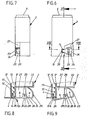
- the housing 2 which forms a tablet receiving space 1 with its predominant volume fraction, is box-shaped, with the exception of the seventh exemplary embodiment.
- the filling content consists of disc-shaped material, such as tablets 3.
- This content is separated by means of a linear, for example vertically or horizontally displaceable slide 4.
- the latter is frame-shaped and merges upwards into an exposed actuation button 5.
- It is a cap-shaped component which closes off the entire clear cross section of the receiving space 1 and which, acting practically as a housing wall, closes off the supply by closing it at the top.
- the actuation button 5 can be molded onto the slide 4 in the same way.
- the two vertical legs of the frame-shaped slide 4 run in guides formed by strips 6 (see FIG. 10).
- the lower section of the slide 4 which practically forms a tablet lock or an output cross section 7 adapted to the tablet size, forms a section extending from vertical leg to vertical leg Sidewall 8. In terms of construction, it is the slightly wider, bottom-side slide frame leg.
- the slide 4 In the basic slide position (FIG. 10), the slide 4 assumes a position in which its side wall 8 projects beyond an inner throat K of two housing bottom walls 9 which run inclined to one another in a roof shape. This protrusion can correspond to the tablet diameter.
- the upper edge 8 'of the side wall 8 runs horizontally, slightly stepped in the middle region.
- the side wall 8 forms a side rib 10 in the area of its lower edge 8 ′′.
- the upper side forms a slide or roller ramp 11 for the tablets 3 standing upright on it.
- the roller ramp 11 drops relatively steeply in the direction of the discharge cross section 7 (approx. 30 In the closed position (FIG. 10), this dispensing cross section 7 is kept closed from the outside by the housing wall 12 extending in front of it. Only when the slide 4 is displaced downwards does the dispensing cross section 7 come into congruent position with a tablet drop opening 13 in said housing wall 12.
- the outlet opening 13 is formed by a slot which extends in the direction of displacement, and a nose 14, which acts as a stroke limiter and latching means between the slide and the housing, projects into the slot 14.
- the guide play between the slide 4 and the inner wall of the housing permits the corresponding latching movement
- the outside of the nose closes substantially level with the From the casing wall.
- the slide receives additional guidance in the lower region through a narrow shaft 15 which is drawn in just above the base of the housing.
- the latter is essentially aligned with the guides formed by the strips 6.
- the shaft 15 is formed by vertical sections 9 ′ of the same directly adjoining the inclined bottom walls 9.
- the shaft 15 is filled in half essentially by the sides wand 8, while the other half creates an orderly collecting shaft for the tablets.
- Two compartment fingers 16, 17 extend from the shaft-limiting section 9 'on the right in FIG. 4. The latter extend in the direction of slide movement and intersect the side rib 10 which forms the rolling ramp and which has passage openings 18, 19 corresponding to the rib cross section.
- the parallel distance between the two compartment fingers 16, 17 is chosen to be smaller than the diameter of a tablet 3.
- the compartment fingers 16 and 17 only reach through the through openings 18, 19 when the slide 4 is lowered. They then loosen up and hold back the penultimate tablet. With the lowering of the roller ramp 11, the tablets 3 lined up in the dispensing direction are easily displaced and loosened in this relative movement between the side wall 8 on the one hand and the right-hand shaft-forming section 9 'on the other hand, so that no roof shingled, jamming overlap position of the tablets is possible, which is the case everything else can occur with lenticular tablet bodies.
- the slide Above the stationary compartment finger 16, the slide forms a deflection shoulder 20, which runs parallel above or to the rolling ramp 11 and, at about the height of the compartment finger 16 there, merges into a cut-back shoulder section which runs into the vertical leg of the frame-shaped slider there.
- the deflection shoulder 20 forms, together with the side rib section lying on the right side of the passage opening 18, a kind of directional funnel.
- the springs loading the slider 4 in the direction of its basic position are designated by 21 and the slider 4 is integrally formed.
- the distance between the actuation button 5 and the lock Sp arranged in the region of the lower end of the housing side wall 12 has a dimension which is greater than the span of a child's hand.
- Accidental touches of the somewhat protruding actuation button 5, for example when gripping the dispenser no longer lead to a tablet dispensing. Rather, the handling has to be voluntary and to a certain extent also concentrated.
- the lock Sp is implemented as a double-armed rocker arm 23 which can be actuated transversely to the slide displacement.
- One of its rocker arms a forms the actuating surface 24. It continues into an underfolded spring section 25, which is supported on the housing side.
- These can be molded, relatively narrow, curved strips of material.
- rocker arm b ends at the end in a locking finger 26 which, in the locked position, engages under the shoulder of the slide formed by the nose 14.
- the rocker arm 23 is attached. This requires the locking finger 26 to be angled in the direction of the tablet outlet opening 13, the forked spring section 25, for example, being supported on the housing wall 12 of the dispenser housing 2.
- the lock Sp is located in a lateral indentation 27 located in a corner region of the housing wall 12. It is recessed in such a way that the outer surface of the rocker arm 23 is flush with the outer surface of the housing wall 12.
- the blocking finger 26 thus lies laterally into the outlet opening 13, for which purpose the slot forming this outlet opening is opened in the direction of the bulge 27 by partially cutting back the section 9 ′ of the shaft 15.
- the swivel range of the rocker arm 23 takes into account an angular dimension such that the locking finger 26 moves into a position from the tablet drop opening 13 of more than the diameter of a tablet 3, that is to say completely clears the slot area.
- the rocker arm is assigned by means of a clip connection.
- clip flaps 28 extend from the inside of the rocker arm 23, which grip upward and downward, coaxially lying stub axles as the bearing axis 30 of a bearing arm 29 on the housing side.
- the radially partially open bearing cavity 28 'of the clip flaps 28 is slightly behind the diameter of the stub axle. It ends on the housing side in a kind of catch funnel, which facilitates the assignment of clips.
- the bearing tabs 28 partially overlap the upper and lower sides of the bearing arm 29, which provide an axial securing of the position. In the case of the first exemplary embodiment (FIG. 4), the bearing tabs 28 run continuously.
- bearing journals 30 They encompass a correspondingly continuous bearing journal as the bearing axis 30.
- the latter starts from the housing wall 12 as a hook-shaped projection.
- the axial, downward-facing end of the Bearing thickened somewhat.
- the upper axial limit stop is created by the bearing arm 29 which is directed toward the housing wall 12 and is rooted therein.
- rocker arms a, b are of unequal length in such a way that the rocker arm b forming the locking finger 26 is longer than the other rocker arm a having the actuating surface 24.
- the ratio is about 2: 1. This requires higher actuation forces.
- the latter can be placed there directly, resulting in a relief that is gentle on the bearing points of the rocker arm.
- the basic design of the third exemplary embodiment corresponds strongly to the two previously described exemplary embodiments.
- the slider 4 also forms a lowerable roller ramp 11 there for the tablets 3 standing upright on it.
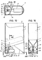
- a nose 31 pointing in the direction of displacement extends from the underside of the side rib 10 of the slider 4 forming the roller ramp 11.
- the latter is in the spring-loaded green position of the lock Sp in front of the top of two pushbuttons 32.
- These pushbuttons 32 which are arranged in pairs and in opposite directions, form a common scanning recess 34 by means of grooves 33 (cf. FIG. 12).
- the grooves 33 which face each other for this purpose, then form a recess cross-section which corresponds to that of the nose 31, so that this can then be immersed by pushing the button 4 downward by moving the slide 4. This leads to the release of the tablet on the dispensing side and the blocking of the remaining supply in the manner explained above.
- Each feeler bar 32 is connected to the rocker arm 23 via a film hinge 35.
- the arm b forming the lock Sp via the pushbuttons 32 has the actuating surface 24 in its back; the much shorter rocker arm a defines the basic position of the rocker arm by stepping with its narrow side facing the tablet receiving space 1 against the underside of the respective bottom wall 9, in the area of which the rocker arm 23 is articulated.
- a spring section 25 extends on the inside, which is supported on the shaft-forming section 9 'of the shaft 15, the latter having congruent guide openings 36 for the pushbuttons 32 crossing the slide 4.
- the spring sections 25 per rocker arm 23 are also formed in pairs here.
- Axle stubs 37 are also formed on the rocker arm. The connection is irreversible. The axial sections of the stub axles 37 continue into holding arms 37 'which extend at right angles and are rooted in the inside of the rocker arm 23.
- the release position of the locks Sp is also stop-defined, be it that they come with their free ends against the inside of the rocker arm 23, or that the spring section 25 moves into the inner corner 39 between the shaft-forming section 9 'and the sloping bottom wall 9 to limit displacement.
- the slide 4 has a guide tab 40.
- the latter is provided in pairs and extends at the level of the deflection shoulder 20 of the slide.
- Such guide tabs run on the inner surface of the narrower wall of the housing, to the side of the tablet discharge cross section 7, which they also stabilize.
- the lock Sp interacts here with the lower shoulder 40 'of one of the guide tabs 40.
- the lock is in turn formed by a rocker arm 23, whose rocker arm b forming the locking finger 26 is immersed in a window-like recess 41 of the side wall 12 of the housing in the locked position. It is a narrow wall.
- the broad side wall receives the rocker arm 23 in a contour-appropriate recess, so that only a corner-spanning section of the rocker arm b is immersed in said niche, which is perpendicular to the wide side wall of the housing.
- the corresponding positive engagement allows the operating force of the actuation button 5 to flow into the housing 2 in the unlocked state.
- the axle bearings of the rocker arm are therefore largely protected.
- the locking finger has a width which corresponds to the thickness of the housing wall 12 and that of the guide tab 40.
- the other rocker arm a forms the actuating surface 24 with its outer side.
- the spring 21 which loads the slide 4 in the direction of its basic position is rooted in the housing, namely near the bottom, in order to step with its free end against the underside of the slide or roller ramp 11 of the slide.
- the lock Sp must also be released here first; then the way becomes free for the vertical displacement of the slide 4 by means of the actuation button 5
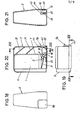
- the fifth exemplary embodiment provides for a horizontal displacement of the slide 4, which in turn is loaded with springs 21 which are molded onto it in the direction of the basic position shown in FIG. 20.
- the reference numbers are used accordingly.
- the function of the roller ramp 11 and the tablet drop opening 13, which is offset from the tablet discharge cross section 7, also result from the above-mentioned figure, which, however, does not lie here in the side wall of the housing, but in the bottom 22 of the same.
- a displaceable compartment finger 16 is used here, the free end of which forms the locking finger 26 of the lock Sp.
- the configuration consists in that the lock Sp cooperates with a projection of a slide button 42 which is transverse to it, that is to say vertically, opposite the horizontal opening displacement direction of the slide 4 and at the same time forms the compartment finger 18.
- the compartment finger 16 extends in the spring-loaded basic position (FIG. 20) in a blocking manner in front of the front wall 4 'of the slide 4 there, which in the release position can be moved into a position separating the dispensing tablet from the remaining supply in accordance with the passage opening 18 in its front wall 4'.
- the slide button 42 runs in a vertical slot 43 of the housing 2. Its fixing and guiding is obtained from a locking projection 44 passing through the vertical slot 43. From the underside of this locking projection 44, which is tapered like a roof in the insertion direction, a spring section 25, which in turn is formed in the same way, extends. The latter is supported on the bottom 22 of the housing.
- the horizontally oriented compartment finger 16 runs in a separate vertical slot 45 (see FIG. 21).
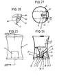
- the sixth embodiment again specifies a horizontally oriented slide displacement.
- the locking principle is particularly clear from Fig. 23.
- the rocker arm 23 which is spring-loaded in the direction of its basic position, projects with its arm b into the path of movement of a slide projection 46. It is a bar that is molded on at the same time. This protrudes at right angles from the flat slide and points into the interior of the housing 2, into which the end of the rocker arm b forming the actual lock also extends freely.
- the actuating surface 24, on the other hand is in turn formed by the outside of the arm a, from the free end of which the molded-on spring section 25, which is supported on the opposite broad side wall of the housing, extends. This spring section is also provided twice.
- the seventh embodiment also takes up the principle of horizontal slide displacement.
- the lock Sp is formed there by an angular rocker arm 23, which points in the opposite direction of displacement (to the right) of the slide 4 and is mounted in the apex 47, the free end of which arm b lies in the spring-loaded basic position with its free end in front of the end wall 4 'of the slide 4, but which in its release position plunges into the open angular space 48 between this arm b and the arm a forming the actuating surface 24.
- the pivoting range of the rocker arm 23 takes into account the distance required for releasing the tablet ready for dispensing to the tablet drop opening 13 formed here by a bottom opening.
- the arm a of the rocker arm 23 lies in the spring-loaded basic position in the wall plane of the waist-like retracted, rotationally symmetrical housing 2.
- the actuation button 5 lies diametrically opposite the rocker arm, ie its actuation surface 24 formed by the arm a.
- an axial stub clip assignment is also used here. 28 shows the cross section of the stub ends forming a run-up surface. Bearing bushes 38 are in turn molded onto this housing 2.
Landscapes
- Engineering & Computer Science (AREA)
- Mechanical Engineering (AREA)
- Medical Preparation Storing Or Oral Administration Devices (AREA)
- Formation And Processing Of Food Products (AREA)
- Closures For Containers (AREA)
Priority Applications (1)
| Application Number | Priority Date | Filing Date | Title |
|---|---|---|---|
| AT86101302T ATE37006T1 (de) | 1985-04-27 | 1986-01-31 | Spender zur ausgabe von tabletten. |
Applications Claiming Priority (2)
| Application Number | Priority Date | Filing Date | Title |
|---|---|---|---|
| DE3515302 | 1985-04-27 | ||
| DE19853515302 DE3515302A1 (de) | 1985-04-27 | 1985-04-27 | Spender zur ausgabe von tabletten |
Publications (3)
| Publication Number | Publication Date |
|---|---|
| EP0199900A2 true EP0199900A2 (fr) | 1986-11-05 |
| EP0199900A3 EP0199900A3 (en) | 1987-08-26 |
| EP0199900B1 EP0199900B1 (fr) | 1988-09-07 |
Family
ID=6269316
Family Applications (1)
| Application Number | Title | Priority Date | Filing Date |
|---|---|---|---|
| EP86101302A Expired EP0199900B1 (fr) | 1985-04-27 | 1986-01-31 | Distributeur de tablettes |
Country Status (4)
| Country | Link |
|---|---|
| US (1) | US4767023A (fr) |
| EP (1) | EP0199900B1 (fr) |
| AT (1) | ATE37006T1 (fr) |
| DE (2) | DE3515302A1 (fr) |
Cited By (5)
| Publication number | Priority date | Publication date | Assignee | Title |
|---|---|---|---|---|
| EP0391841A3 (en) * | 1989-04-04 | 1990-11-28 | Createchnic Ag | Childproof pill dispenser |
| FR2656284A1 (fr) * | 1989-12-26 | 1991-06-28 | Plastohm | Dispositif de conditionnement et de distribution, un a un, de produits solides comme des grains, granules, comprimes ou analogues. |
| WO1996021111A1 (fr) * | 1994-12-30 | 1996-07-11 | Haas Beteiligungsgesellschaft Mbh | Ressort en plastique |
| EP1002745A1 (fr) * | 1998-11-17 | 2000-05-24 | Sanaro S.A. | Bouton-poussoir avec ressort et distributeur de pillules comportant un tel bouton-poussoir |
| RU2173802C2 (ru) * | 1994-12-30 | 2001-09-20 | Хаас Бетайлигунгсгезелльшафт МбХ | Пластмассовая пружина |
Families Citing this family (51)
| Publication number | Priority date | Publication date | Assignee | Title |
|---|---|---|---|---|
| CH672772A5 (fr) * | 1987-03-20 | 1989-12-29 | Alfatechnic Ag | |
| DE8815878U1 (de) * | 1988-06-09 | 1989-10-12 | Bramlage Gmbh, 2842 Lohne | Spender zur einzel-portionierten Ausgabe von Tabletten |
| US5108006A (en) * | 1990-04-27 | 1992-04-28 | The Procter & Gamble Company | Tablet dispenser with locking means |
| US5208762A (en) * | 1990-12-06 | 1993-05-04 | Baxter International Inc. | Automated prescription vial filling system |
| USRE37829E1 (en) * | 1990-12-06 | 2002-09-03 | Automed Technologies, Inc. | Automated prescription vial filling system |
| GB2257421A (en) * | 1991-07-02 | 1993-01-13 | Audus Noble Ltd | Tablet dispenser |
| DK196291D0 (da) * | 1991-12-05 | 1991-12-05 | Novo Nordisk As | Apparat |
| GB2270906B (en) * | 1992-08-19 | 1995-08-23 | Manuplastics Ltd | A tablet dispenser |
| US5348061B1 (en) * | 1992-12-01 | 1999-10-12 | Baxter Int | Tablet accumulator for an automated prescription vial filling system |
| US5385267A (en) * | 1993-10-18 | 1995-01-31 | 1 | Portable dispenser for generally spherical confectioneries |
| US5816441A (en) * | 1996-01-25 | 1998-10-06 | Kerr Group, Inc. | Tablet dispenser with child-resistant locking feature |
| US5657901A (en) * | 1996-02-05 | 1997-08-19 | Kerr Group, Inc. | Tablet dispenser with child-resistant locking feature |
| US6131765A (en) * | 1999-01-08 | 2000-10-17 | Barry; William Dean | Device for storing and dispensing solid-form medication |
| PL362083A1 (en) * | 2000-10-13 | 2004-10-18 | Cadbury Schweppes Plc | Tablet dispenser for dispensing individual tablets |
| US6824011B1 (en) * | 2001-09-19 | 2004-11-30 | Woempner Machine Company, Inc. | Pellet dispenser and method |
| US6971541B2 (en) * | 2002-05-14 | 2005-12-06 | Parata Systems, Inc. | System and method for dispensing prescriptions |
| DE20304148U1 (de) * | 2003-03-14 | 2004-07-22 | Rpc Bramlage Gmbh | Tablettenspender |
| US8141330B2 (en) | 2004-05-20 | 2012-03-27 | KNAPP Logistics Automation, Inc. | Systems and methods of automated tablet dispensing, prescription filling, and packaging |
| US7344049B2 (en) | 2005-04-21 | 2008-03-18 | Parata Systems, L.L.C. | Devices useful in system and method for dispensing prescriptions |
| US20070000938A1 (en) * | 2005-04-26 | 2007-01-04 | Renaud Michel C | Tablet dispenser |
| US7909195B2 (en) | 2005-09-23 | 2011-03-22 | Wm. Wrigley Jr. Company | Two-piece container lid assembly |
| US20070196542A1 (en) * | 2005-09-23 | 2007-08-23 | Wm. Wrigley Jr. Company | Consumable product container assembly |
| US8261936B2 (en) | 2006-11-14 | 2012-09-11 | Parata Systems, Llc | Device for dispensing vials useful in system and method for dispensing prescriptions |
| US20080110555A1 (en) * | 2006-11-14 | 2008-05-15 | Steve Bouchelle | Device and method for labeling vials useful in system for dispensing prescriptions |
| US7770358B2 (en) * | 2007-01-17 | 2010-08-10 | Parata Systems, Llc | Devices for capping vials useful in system and method for dispensing prescriptions |
| US7596932B2 (en) * | 2007-01-17 | 2009-10-06 | Parata Systems, Llc | Devices for capping vials useful in system and method for dispensing prescriptions |
| US20100307108A1 (en) * | 2007-01-17 | 2010-12-09 | John Richard Sink | Devices for Capping Vials Useful in System and Method for Dispensing Prescriptions |
| US8056760B2 (en) * | 2007-01-22 | 2011-11-15 | Parata Systems, Llc | Cap dispensing devices useful in system and method for dispensing prescriptions |
| NL2000463C2 (nl) * | 2007-02-01 | 2008-08-04 | Ind Ontwerpbureau Hsm B V | Inrichting voor het dispenseren van korrelvormige producten. |
| US20080245810A1 (en) * | 2007-04-05 | 2008-10-09 | Parata Systems, Llc | Methods and apparatus for dispensing solid pharmaceutical articles |
| US7837061B2 (en) * | 2007-05-18 | 2010-11-23 | Parata Systems, Llc | Methods and apparatus for dispensing solid pharmaceutical articles |
| US7949427B2 (en) * | 2007-05-18 | 2011-05-24 | Parata Systems, Llc | Methods and apparatus for dispensing solid articles |
| US7832591B2 (en) | 2007-05-18 | 2010-11-16 | Parata Systems, Llc | Methods and apparatus for dispensing solid pharmaceutical articles |
| US20090032547A1 (en) * | 2007-07-31 | 2009-02-05 | Theresa Litherland | Three button actuated pill holder/dispenser |
| DE202007013517U1 (de) * | 2007-09-27 | 2007-12-20 | Pöppelmann Holding GmbH & Co. KG | Spender o.dgl. Ausgabebehälter |
| US7870973B2 (en) * | 2008-01-09 | 2011-01-18 | Parata Systems, Llc | Methods and apparatus for dispensing solid articles |
| US8616409B2 (en) * | 2008-01-16 | 2013-12-31 | Parata Systems, Llc | Devices for dispensing objects useful in system and method for dispensing |
| US8464901B2 (en) | 2008-05-05 | 2013-06-18 | Parata Systems, Llc | Methods and apparatus for dispensing solid articles |
| US8827113B2 (en) * | 2008-05-30 | 2014-09-09 | Parata Systems, Llc | Methods and apparatus for dispensing solid articles |
| US8444130B2 (en) * | 2008-09-30 | 2013-05-21 | Parata Systems, Llc | Devices for capping vials useful in system and method for dispensing prescriptions |
| US8054086B2 (en) | 2009-06-25 | 2011-11-08 | Parata Systems, Llc | Apparatus for dispensing and detecting solid pharmaceutical articles and related methods of operation |
| US8413410B2 (en) | 2010-04-30 | 2013-04-09 | Parata Systems, Llc | Devices for capping vials useful in system and method for dispensing prescriptions |
| USD684851S1 (en) | 2011-03-29 | 2013-06-25 | Kraft Foods Global Brands Llc | Combined confectionary product package and dispenser |
| USD680858S1 (en) | 2011-03-29 | 2013-04-30 | Kraft Foods Global Brands Llc | Combined confectionary product package and dispenser |
| DE102011117623B3 (de) * | 2011-11-04 | 2013-02-14 | Boehringer Ingelheim International Gmbh | Tablettenspender |
| US20130233246A1 (en) * | 2012-03-12 | 2013-09-12 | Topet International Co., Limited | Treat dispenser |
| USD924328S1 (en) | 2019-11-26 | 2021-07-06 | Applestone Meat Company Llc | Inner shell of an item carrier |
| USD924330S1 (en) | 2019-11-26 | 2021-07-06 | Applestone Meat Company Llc | Item carrier |
| USD924329S1 (en) | 2019-11-26 | 2021-07-06 | Applestone Meat Company Llc | Outer shell of an item carrier |
| PL241783B1 (pl) * | 2020-02-29 | 2022-12-05 | Rosinski Packaging Spolka Z Ograniczona Odpowiedzialnoscia | Dozownik |
| US12036185B2 (en) | 2021-07-19 | 2024-07-16 | Optum, Inc. | System and method to count pills |
Family Cites Families (15)
| Publication number | Priority date | Publication date | Assignee | Title |
|---|---|---|---|---|
| US1889232A (en) * | 1932-04-21 | 1932-11-29 | Package Improvement Co Inc | Cigarette package |
| US2559287A (en) * | 1949-04-14 | 1951-07-03 | Duell | Dispensing container |
| US3102662A (en) * | 1961-07-03 | 1963-09-03 | Russel S Crabtree | Safety tablet dispenser |
| FR1328990A (fr) * | 1962-04-25 | 1963-06-07 | S E D A T | Tube distributeur de granules |
| US3159308A (en) * | 1963-05-14 | 1964-12-01 | Passavanti Lawrence | Article dispensing device comprising a pair of tubular members |
| US3471056A (en) * | 1967-11-29 | 1969-10-07 | Stephen Robert Kovac | Article dispenser having a reciprocating ejector |
| US3866796A (en) * | 1973-08-31 | 1975-02-18 | Continental Can Co | Childproof pill dispenser |
| US3921851A (en) * | 1974-02-25 | 1975-11-25 | Billy N Nilson | Disabling device for dispenser for tablets |
| US4124143A (en) * | 1977-02-11 | 1978-11-07 | Ryder International Corporation | Pill dispenser |
| GB2013636A (en) * | 1977-10-28 | 1979-08-15 | Boots Co Ltd | Container |
| US4428502A (en) * | 1980-03-25 | 1984-01-31 | Veltri Douglas F | Lockable pocket-size tablet dispensing device |
| CH647475A5 (de) * | 1980-07-09 | 1985-01-31 | Leer Verpackungen Gmbh | Einzeldosierdose fuer tabletten. |
| DE3301217C2 (de) * | 1982-06-09 | 1985-09-05 | Müller's Mühle Schneekoppe AG, 4650 Gelsenkirchen | Vorrichtung zur dosierten Abgabe von Tabletten |
| EP0113219B1 (fr) * | 1982-12-21 | 1987-11-19 | Johnsen & Jorgensen (Plastics) Limited | Récipient distributeur |
| DE3410005A1 (de) * | 1984-03-19 | 1985-09-19 | Bramlage Gmbh, 2842 Lohne | Kindersicherung an behaeltnissen, insbesondere tablettenportionierern |
-
1985
- 1985-04-27 DE DE19853515302 patent/DE3515302A1/de not_active Withdrawn
-
1986
- 1986-01-31 EP EP86101302A patent/EP0199900B1/fr not_active Expired
- 1986-01-31 AT AT86101302T patent/ATE37006T1/de not_active IP Right Cessation
- 1986-01-31 DE DE8686101302T patent/DE3660667D1/de not_active Expired
- 1986-04-18 US US06/853,741 patent/US4767023A/en not_active Expired - Fee Related
Cited By (6)
| Publication number | Priority date | Publication date | Assignee | Title |
|---|---|---|---|---|
| EP0391841A3 (en) * | 1989-04-04 | 1990-11-28 | Createchnic Ag | Childproof pill dispenser |
| FR2656284A1 (fr) * | 1989-12-26 | 1991-06-28 | Plastohm | Dispositif de conditionnement et de distribution, un a un, de produits solides comme des grains, granules, comprimes ou analogues. |
| WO1996021111A1 (fr) * | 1994-12-30 | 1996-07-11 | Haas Beteiligungsgesellschaft Mbh | Ressort en plastique |
| US5984285A (en) * | 1994-12-30 | 1999-11-16 | Haas Beteiligungsgesellschaft M.B.H. | Plastic spring |
| RU2173802C2 (ru) * | 1994-12-30 | 2001-09-20 | Хаас Бетайлигунгсгезелльшафт МбХ | Пластмассовая пружина |
| EP1002745A1 (fr) * | 1998-11-17 | 2000-05-24 | Sanaro S.A. | Bouton-poussoir avec ressort et distributeur de pillules comportant un tel bouton-poussoir |
Also Published As
| Publication number | Publication date |
|---|---|
| ATE37006T1 (de) | 1988-09-15 |
| EP0199900B1 (fr) | 1988-09-07 |
| US4767023A (en) | 1988-08-30 |
| EP0199900A3 (en) | 1987-08-26 |
| DE3660667D1 (en) | 1988-10-13 |
| DE3515302A1 (de) | 1986-10-30 |
Similar Documents
| Publication | Publication Date | Title |
|---|---|---|
| EP0199900B1 (fr) | Distributeur de tablettes | |
| DE69115478T2 (de) | Tablettenspender mit verschlussvorrichtung | |
| DE3244645C2 (fr) | ||
| CH647474A5 (de) | Behaeltnis zur einzel-portionierten ausgabe von tabletten. | |
| DE29514137U1 (de) | Tablettenspender | |
| EP0217390B1 (fr) | Dispositif pour la décharge en portions de produits granuleux, cachets et similaires | |
| EP0290972A1 (fr) | Distributeur de pilules à l'unité | |
| DE2922350A1 (de) | Behaeltnis zur einzel-portionierten ausgabe von tabletten | |
| EP0675840A1 (fr) | Contenant pour la distribution individuelle de comprimes ou produits analogues | |
| DE3210361C2 (fr) | ||
| EP0248278A2 (fr) | Distributeur pour délivrer les doses unitaires d'une pâte ou similaire | |
| EP0408774B1 (fr) | Distributeur de comprimés pour la distribution individuelle de comprimés | |
| EP0786420B1 (fr) | Distributeur de comprimés pour la distribution individuelle de comprimés | |
| EP0478687B1 (fr) | Recipient, notamment pour produits coulants | |
| EP1606193B1 (fr) | Distributeur de pastilles | |
| DE10117910C1 (de) | Arzneimittelbehälter mit Kindersicherung | |
| DE19909799A1 (de) | Tablettenspender mit einem zumindest an der Innenseite im wesentlichen zylindrischen Behälter | |
| EP0084617A1 (fr) | Fermeture pour récipient avec couvercle rabattable | |
| DE8907662U1 (de) | Verpackungsbehälter | |
| EP0600123A1 (fr) | Distributeur de pilules avec orifice de distribution dans sa base | |
| EP0822151B1 (fr) | Distributeur de pilules avec boítier extérieur et récipient | |
| CH478699A (de) | Behälter mit einer Ausschubvorrichtung für Bonbons | |
| DE3022411A1 (de) | Behaelter zur einzel-portionierten ausgabe von tabletten | |
| DE29601042U1 (de) | Tablettenspender zur Einzeldosierung von Tabletten | |
| DE3342884A1 (de) | Kindersichere schutzkappe fuer aerosolspruehdosen |
Legal Events
| Date | Code | Title | Description |
|---|---|---|---|
| PUAI | Public reference made under article 153(3) epc to a published international application that has entered the european phase |
Free format text: ORIGINAL CODE: 0009012 |
|
| AK | Designated contracting states |
Kind code of ref document: A2 Designated state(s): AT BE CH DE FR GB IT LI LU NL SE |
|
| PUAL | Search report despatched |
Free format text: ORIGINAL CODE: 0009013 |
|
| AK | Designated contracting states |
Kind code of ref document: A3 Designated state(s): AT BE CH DE FR GB IT LI LU NL SE |
|
| 17P | Request for examination filed |
Effective date: 19870820 |
|
| 17Q | First examination report despatched |
Effective date: 19871126 |
|
| GRAA | (expected) grant |
Free format text: ORIGINAL CODE: 0009210 |
|
| AK | Designated contracting states |
Kind code of ref document: B1 Designated state(s): AT BE CH DE FR GB IT LI LU NL SE |
|
| REF | Corresponds to: |
Ref document number: 37006 Country of ref document: AT Date of ref document: 19880915 Kind code of ref document: T |
|
| REF | Corresponds to: |
Ref document number: 3660667 Country of ref document: DE Date of ref document: 19881013 |
|
| ET | Fr: translation filed | ||
| GBT | Gb: translation of ep patent filed (gb section 77(6)(a)/1977) | ||
| ITF | It: translation for a ep patent filed | ||
| PGFP | Annual fee paid to national office [announced via postgrant information from national office to epo] |
Ref country code: AT Payment date: 19890123 Year of fee payment: 4 |
|
| PG25 | Lapsed in a contracting state [announced via postgrant information from national office to epo] |
Ref country code: LU Free format text: LAPSE BECAUSE OF NON-PAYMENT OF DUE FEES Effective date: 19890131 |
|
| PGFP | Annual fee paid to national office [announced via postgrant information from national office to epo] |
Ref country code: BE Payment date: 19890131 Year of fee payment: 4 Ref country code: NL Payment date: 19890131 Year of fee payment: 4 |
|
| PG25 | Lapsed in a contracting state [announced via postgrant information from national office to epo] |
Ref country code: SE Effective date: 19890201 |
|
| PLBE | No opposition filed within time limit |
Free format text: ORIGINAL CODE: 0009261 |
|
| STAA | Information on the status of an ep patent application or granted ep patent |
Free format text: STATUS: NO OPPOSITION FILED WITHIN TIME LIMIT |
|
| 26N | No opposition filed | ||
| PG25 | Lapsed in a contracting state [announced via postgrant information from national office to epo] |
Ref country code: AT Effective date: 19900131 Ref country code: BE Effective date: 19900131 |
|
| BERE | Be: lapsed |
Owner name: BRAMLAGE G.M.B.H. Effective date: 19900131 |
|
| PG25 | Lapsed in a contracting state [announced via postgrant information from national office to epo] |
Ref country code: NL Effective date: 19900801 |
|
| NLV4 | Nl: lapsed or anulled due to non-payment of the annual fee | ||
| ITTA | It: last paid annual fee | ||
| PGFP | Annual fee paid to national office [announced via postgrant information from national office to epo] |
Ref country code: CH Payment date: 19910419 Year of fee payment: 6 |
|
| PGFP | Annual fee paid to national office [announced via postgrant information from national office to epo] |
Ref country code: FR Payment date: 19911224 Year of fee payment: 7 |
|
| PGFP | Annual fee paid to national office [announced via postgrant information from national office to epo] |
Ref country code: GB Payment date: 19920117 Year of fee payment: 7 |
|
| PG25 | Lapsed in a contracting state [announced via postgrant information from national office to epo] |
Ref country code: LI Effective date: 19920131 Ref country code: CH Effective date: 19920131 |
|
| REG | Reference to a national code |
Ref country code: CH Ref legal event code: PL |
|
| PG25 | Lapsed in a contracting state [announced via postgrant information from national office to epo] |
Ref country code: GB Effective date: 19930131 |
|
| GBPC | Gb: european patent ceased through non-payment of renewal fee |
Effective date: 19930131 |
|
| PG25 | Lapsed in a contracting state [announced via postgrant information from national office to epo] |
Ref country code: FR Effective date: 19930930 |
|
| REG | Reference to a national code |
Ref country code: FR Ref legal event code: ST |
|
| EUG | Se: european patent has lapsed |
Ref document number: 86101302.7 Effective date: 19900118 |
|
| PGFP | Annual fee paid to national office [announced via postgrant information from national office to epo] |
Ref country code: DE Payment date: 20021204 Year of fee payment: 18 |
|
| PG25 | Lapsed in a contracting state [announced via postgrant information from national office to epo] |
Ref country code: DE Free format text: LAPSE BECAUSE OF NON-PAYMENT OF DUE FEES Effective date: 20040803 |
|
| PG25 | Lapsed in a contracting state [announced via postgrant information from national office to epo] |
Ref country code: IT Free format text: LAPSE BECAUSE OF NON-PAYMENT OF DUE FEES;WARNING: LAPSES OF ITALIAN PATENTS WITH EFFECTIVE DATE BEFORE 2007 MAY HAVE OCCURRED AT ANY TIME BEFORE 2007. THE CORRECT EFFECTIVE DATE MAY BE DIFFERENT FROM THE ONE RECORDED. Effective date: 20050131 |