EP0199983A1 - Commutateur électrique - Google Patents
Commutateur électrique Download PDFInfo
- Publication number
- EP0199983A1 EP0199983A1 EP86103980A EP86103980A EP0199983A1 EP 0199983 A1 EP0199983 A1 EP 0199983A1 EP 86103980 A EP86103980 A EP 86103980A EP 86103980 A EP86103980 A EP 86103980A EP 0199983 A1 EP0199983 A1 EP 0199983A1
- Authority
- EP
- European Patent Office
- Prior art keywords
- actuating member
- switch according
- housing
- slide
- actuating
- Prior art date
- Legal status (The legal status is an assumption and is not a legal conclusion. Google has not performed a legal analysis and makes no representation as to the accuracy of the status listed.)
- Granted
Links
- 238000006073 displacement reaction Methods 0.000 claims description 10
- 210000003608 fece Anatomy 0.000 claims 1
- 238000004519 manufacturing process Methods 0.000 description 2
- 238000004873 anchoring Methods 0.000 description 1
- 230000000994 depressogenic effect Effects 0.000 description 1
- 238000005553 drilling Methods 0.000 description 1
- 230000000694 effects Effects 0.000 description 1
- 230000002349 favourable effect Effects 0.000 description 1
- 230000008719 thickening Effects 0.000 description 1
- XLYOFNOQVPJJNP-UHFFFAOYSA-N water Substances O XLYOFNOQVPJJNP-UHFFFAOYSA-N 0.000 description 1
Images
Classifications
-
- H—ELECTRICITY
- H01—ELECTRIC ELEMENTS
- H01H—ELECTRIC SWITCHES; RELAYS; SELECTORS; EMERGENCY PROTECTIVE DEVICES
- H01H21/00—Switches operated by an operating part in the form of a pivotable member acted upon directly by a solid body, e.g. by a hand
- H01H21/02—Details
- H01H21/04—Cases; Covers
- H01H21/10—Casing of switch constituted by a handle serving a purpose other than the actuation of the switch
-
- H—ELECTRICITY
- H01—ELECTRIC ELEMENTS
- H01H—ELECTRIC SWITCHES; RELAYS; SELECTORS; EMERGENCY PROTECTIVE DEVICES
- H01H19/00—Switches operated by an operating part which is rotatable about a longitudinal axis thereof and which is acted upon directly by a solid body external to the switch, e.g. by a hand
- H01H19/54—Switches operated by an operating part which is rotatable about a longitudinal axis thereof and which is acted upon directly by a solid body external to the switch, e.g. by a hand the operating part having at least five or an unspecified number of operative positions
- H01H19/60—Angularly-movable actuating part carrying no contacts
- H01H19/635—Contacts actuated by rectilinearly-movable member linked to operating part, e.g. by pin and slot
-
- H—ELECTRICITY
- H01—ELECTRIC ELEMENTS
- H01H—ELECTRIC SWITCHES; RELAYS; SELECTORS; EMERGENCY PROTECTIVE DEVICES
- H01H9/00—Details of switching devices, not covered by groups H01H1/00 - H01H7/00
- H01H9/02—Bases, casings, or covers
- H01H9/06—Casing of switch constituted by a handle serving a purpose other than the actuation of the switch, e.g. by the handle of a vacuum cleaner
- H01H9/061—Casing of switch constituted by a handle serving a purpose other than the actuation of the switch, e.g. by the handle of a vacuum cleaner enclosing a continuously variable impedance
Definitions
- the invention relates to an electrical switch with a slidably mounted in the housing, coupled to an actuator and carrying a slider for a potentiometer slide.
- electrical switches are already known in various embodiments. They are usually used for electrically operated hand tools, with the help of the grinder and the potentiometer track, the speed of the motor in front of the oil level can be continuously increased up to a predetermined maximum value. When the grinder has reached its final displacement position or at least a predetermined displacement position, the switch contacts are also closed via the actuating member, thereby bridging the electronics. The engine then runs at the specified maximum speed.
- the actuator is designed as a button that is pressed in the direction of movement of the slide and is usually returned with the aid of a return spring as soon as the actuating force is eliminated.
- actuation via such a push button is not very advantageous. This is mainly due to the fact that gloves are worn when working with such devices, which make it difficult to press the relatively small button and also hardly allow a sensitive adjustment over the control range of the potentiometer.
- the object of the invention is therefore to develop the switch of the type mentioned in such a way that it can be operated more cheaply and despite the different type of actuation, a potentiometer tap of the usual length is possible.
- the electrical switch is designed in accordance with the preamble of claim 1 in accordance with the characterizing part of this claim.
- a rotatably mounted actuating device i.e. a kind of swivel button instead of a push button
- the switch can now be used with several fingers with appropriate dimensioning with all fingers of the hand, which means that the actuator can still be pivoted with sufficient feeling even when using a thick mitt can.
- the - pivotable actuator can be assigned to the handle of the electric hand tool in a particularly favorable manner. Implementation of the turning or. Pivoting movement of the actuator into the necessary translational movement of the slide can be done more easily with the help of the interposed pivoting member. realize cost-effective and robust way.
- a particularly preferred embodiment of the invention provides in this connection that the pivot member is coupled to the slide on the one hand and the actuating member on the other hand in each case via a pin-elongated hole connection.
- Longitudinal spigot connections are easy to manufacture, easy to assemble and, especially when using plastic, maintenance-free.
- the pivot member is designed as a double lever and in particular is approximately C-shaped, wherein the two C-leg ends each engage in a receptacle of the slide or actuator.
- the shape of the swivel member could also be described as angular. Both only approximate the effective design, and the exact shape results from the shape of the other switch parts as well as the available space including the space required for the pivoting movement and the length of the potentiometer.
- a further embodiment of the invention is that the maximum swiveling movement of the actuating member can be changed with the aid of an adjusting device and can thus be preset.
- the largest pivoting movement of the actuating member is associated with the largest pivoting movement of the pivoting member.
- the length of the potentiometer track is designed so that the entire potentiometer track can be used at the maximum angle of rotation of the pivoting member, or vice versa. If you shorten the pivoting angle of the actuating member and thus also that of the pivoting member with the aid of the adjusting device, the pivoting movement of the actuating member ends before the grinder has reached the other end of the potentiometer. That beaeu tet that you can use this setting to preset the maximum achievable speed. This is advantageous, for example, if screws are to be screwed in with a drilling machine, which is known to happen at a very low speed.
- the adjusting device prevents that you accidentally exceed the desired maximum speed due to excessive depression of the actuator.
- a preferred variant of a switch in which the maximum actuation path can be limited by means of a threaded, only _, rotatable adjusting member on the actuating member, provides that the pivoting member is connected indirectly to the actuating member via a lifting member of the adjusting device, the lifting member being connected to the Adjusting member is coupled via a threaded connection and is mounted displaceably in the direction of the rotational movement of the actuating member on the latter, and that the pivoting member is coupled indirectly to the actuating member via the lifting member.
- a switch of this type is known for example from DE-PS 2 045 832. However, this is a type of the type explained at the beginning with a pushbutton.
- the switch according to the invention it is now also possible in a simple and convenient manner to preset the maximum maximum speed of a motor in the circuit of which this electrical switch is installed.
- the actuating member can be pivoted towards the switch housing without changing the starting position of the grinder on the potentiometer path.
- the remaining reduced pivoting angle of the actuating member has the consequence that the grinder is only in the middle of the potentiometer path, for example, when the shortened pivoting movement of the actuating member has ended. The shorter the distance traveled by the grinder on the potentiometer. the lower the maximum speed of the electric motor of the hand tool.
- a further development of the invention is characterized in that the receptacle of the slide has two elongated holes which extend transversely, in particular perpendicularly, to the direction of movement of the latter, into each of which engages a bolt end of a first bolt held in the associated pivot member end.
- Another embodiment of the invention is characterized in that the pivot member end assigned to the actuating member or the lifting member carries a second bolt, the free ends of which are each mounted in a particularly open edge, longitudinal slot of the actuating member or the lifting member, or vice versa, these longitudinal slots being transverse , In particular perpendicular, to the direction of adjustment of the lifting member in the actuator.
- a further preferred embodiment of the invention consists in that the displacement movement of the lifting member is limited by an inner surface of the actuating member on the one hand and a thickened inner end of the threaded spindle of the adjusting member on the other hand, the thickened end being preferably formed by a snap ring or the like.
- the snap ring in particular allows simple and inexpensive assembly and manufacture of the parts in question.
- switch-on position is understood here to mean the switch position in which the movable contact or contacts are present on the fixed switch contacts when the electronics are bridged.
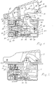
- the slide 2 is displaceable in the sense of the double arrow 3 against the resistance of a return spring 4, which is supported with one end on the housing wall 5 and the other end on the associated slide end 6.
- a return spring 4 which is supported with one end on the housing wall 5 and the other end on the associated slide end 6.
- Moving the slide 2 from the right end position shown in FIG. 1 into the left end position shown in FIG. 2 is achieved with the aid of an actuating member 7 with the interposition of a swivel member 8.
- the latter is rotatably mounted on the housing 1 about an axis 9. It has an approximately C-shaped shape.
- the slide 2 carries a grinder 10 which interacts with a potentiometer track 11 of a potentiometer plate 12 assigned to the bottom 13 of the housing.
- the length of the potentiometer track 11 corresponds approximately to the maximum displacement of the slide 2 and thus also the grinder 10.
- the pivot member is coupled at both ends via a pin-slot connection 14 or 15 with the actuating member 7 on the one hand and the slide 2 on the other.
- the pin-slot connection 14 consists of the slot 16 on the lever arm 18 of the swivel member 8 designed as a two-armed lever on the one hand and an anchoring element 7 actuated in the actuating member 7 Engage protruding ends in each of an elongated hole at the right end of the slide, the two elongated holes of course being congruent. They run approximately perpendicular to the direction of displacement 3.
- the longitudinal axis of the elongated hole 16 in the switch position of the switch extends approximately in the longitudinal direction of the actuating member 7 (FIG. 2).
- the lever arm 19 of the swivel member 8 also extends approximately perpendicular to the direction of displacement 3, while the longitudinal axis of the lever arm 18 in the starting position of the switch. roughly viewed, runs approximately in the longitudinal direction of the actuator 7. Otherwise, the assignments of elongated hole and bolt can also be reversed.
- a contact arm 24 is pivotally mounted in a housing bearing 22 and a further contact arm 25 is mounted in a further housing bearing 23.
- the housing bearing 23 is made in one piece with a connection element 28 of the switch.
- the contact arms 24 and 25 designed as two-armed levers carry movable contacts 26 and 27 which cooperate with fixed contacts 29 and 30, respectively. The latter are located in a known manner on switch connection elements 31 and 32.
- the contact pairs 26 and 29 or 27 and 30 bridge a switch electronics to which the potentiometer 10, 11 belongs.
- Tension springs 33 and 34 which are hooked into a molded-on bolt of the housing on the one hand and are attached with their other end to the left lever arm of their associated contact arm in FIG. 1, are under tension when the contacts are open, and they pull the contact arm into its contacting position as soon as the right lifting arm of each contact arm is released. In the starting position, the free arcuate end of each contact arm rests on an associated cam 35 or 36 of the slide 2.
- a pair of contact arms can also be provided in a manner not shown on the left side of the slide 2, which is visible in FIG. 1, and also on the right side thereof.
- different cam arrangements of the left and right side as well as the upper and lower side are easily possible in order to achieve different switching characteristics.
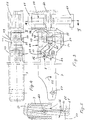
- the second exemplary embodiment of the invention provides for indirect pivoting of the swivel member 8 or swivel member lever arm 18 on the actuating member 7.
- the connection again takes place via the elongated hole 16 and a bolt 17.
- the latter passes through the elongated hole 16 of the swivel member 8, and its free ends engage in an open edge slot 42 of a fork-shaped end 43 of a lifting member 44.
- the bolt 17 could also be fastened firmly in the lever arm 18 of the pivot member 8, and one would still have a mortise and tenon connection over the edge-open slot 42.
- the reverse arrangement of elongated hole or slot and pin is also possible here.
- the lifting member 44 can be adjusted in the sense of the double arrow 45 relative to the actuating member 7.
- a rotatable adjusting member 46 with a preferably knurled head 47 is used for this purpose. Due to a collar 48, the adjusting member 46 is rotatably but immovably mounted in the actuating member 7. In contrast, the lifting member 44 can only be moved up and down, but cannot be rotated in the actuator 7.
- the longitudinal guide is achieved with the aid of two strips 49 and 50 projecting in opposite directions, which engage in corresponding groove-like guides 51 and 52 on opposite walls of the actuating member 7.
- the edge-open slots 42 of the lifting member receptacle 53 run approximately perpendicular to the direction of displacement 45 of the lifting member 44, which of course extends in the axial direction of the adjusting member 46.
- the adjusting member is a screw with a bolt thread 54 which can be screwed into a corresponding nut thread 55 of the lifting member 44.
- the upper end position of the lifting member 44 is determined by an inner surface 56 of the actuating member 7, while the lower end position of the lifting member 44 shown in dash-dotted lines in FIG. 3 is determined by a snap ring 57 or another thickening at the free end of the adjusting member 46.
- the actuating member 7 carries a locking lever 59 which can be pivoted in the direction of the double arrow 60. It is designed as a double-armed lever and is mounted on an axis 62 at the end of the actuating member 7 remote from the axis.
- One of its lever arms carries an actuating handle 63, which is preferably molded on. At the free end of the other lever arm there is a barb-like locking member 61.
- the locking member 61 engages under the transverse edge 64 (FIG. 5) of a wall 65 of a side housing extension of the switch housing 1 extending parallel to the wall 66 of the actuating member 7. Two such walls 65 are expediently attached in parallel, one of which is free End of the locking member 61 can occur. In the inactive position of the locking lever 59, the locking member 61 can be moved along the vertical edge 66 of the wall or walls 65.
- the pivot axis of the actuator 7 is designated 67.
- the bearing 68 of the swivel member 8 passing through the housing 1 is located on the outside and is covered in a dustproof manner by means of a sleeve 69.
Landscapes
- Finish Polishing, Edge Sharpening, And Grinding By Specific Grinding Devices (AREA)
Applications Claiming Priority (2)
| Application Number | Priority Date | Filing Date | Title |
|---|---|---|---|
| DE3512665 | 1985-04-06 | ||
| DE19853512665 DE3512665C2 (de) | 1985-04-06 | 1985-04-06 | Elektrischer Schalter |
Publications (2)
| Publication Number | Publication Date |
|---|---|
| EP0199983A1 true EP0199983A1 (fr) | 1986-11-05 |
| EP0199983B1 EP0199983B1 (fr) | 1989-03-22 |
Family
ID=6267523
Family Applications (1)
| Application Number | Title | Priority Date | Filing Date |
|---|---|---|---|
| EP19860103980 Expired EP0199983B1 (fr) | 1985-04-06 | 1986-03-22 | Commutateur électrique |
Country Status (2)
| Country | Link |
|---|---|
| EP (1) | EP0199983B1 (fr) |
| DE (1) | DE3512665C2 (fr) |
Cited By (6)
| Publication number | Priority date | Publication date | Assignee | Title |
|---|---|---|---|---|
| EP0468622A3 (en) * | 1990-07-27 | 1992-11-19 | Milwaukee Electric Tool Corporation | Variable resistance switch |
| WO1997037364A1 (fr) * | 1996-03-15 | 1997-10-09 | Marquardt Gmbh | Interrupteur electrique |
| WO2010023013A1 (fr) * | 2008-08-25 | 2010-03-04 | Robert Bosch Gmbh | Commutateur principal de commande pour machines-outils électriques, en particulier outils électriques à main, ainsi qu'outil électrique à main |
| US7705260B2 (en) | 2005-04-18 | 2010-04-27 | Xinsheng Xu | Switch assembly |
| US8853578B2 (en) | 2009-12-18 | 2014-10-07 | Milwaukee Electric Tool Corporation | Multi motion switch with multiplier arm |
| CN113380571A (zh) * | 2021-06-25 | 2021-09-10 | 歌尔股份有限公司 | 扳机按键装置和电子设备 |
Families Citing this family (5)
| Publication number | Priority date | Publication date | Assignee | Title |
|---|---|---|---|---|
| NO900020L (no) * | 1989-03-31 | 1990-10-01 | Kransco | Betjeningsmekanisme for bryter. |
| JPH06333462A (ja) * | 1993-05-19 | 1994-12-02 | Daiichi Denso Buhin Kk | 摺動制御部材の回動操作装置 |
| DE10057589C1 (de) * | 2000-11-21 | 2002-07-11 | Erbe Elektromedizin | Fußschalter |
| FR2847889B1 (fr) | 2002-11-29 | 2005-03-04 | Dispositif de distribution de produit fluide | |
| DE102011017453A1 (de) | 2010-04-21 | 2011-10-27 | Marquardt Verwaltungs-Gmbh | Elektrischer Schalter |
Citations (4)
| Publication number | Priority date | Publication date | Assignee | Title |
|---|---|---|---|---|
| US3267223A (en) * | 1964-08-12 | 1966-08-16 | Cutler Hammer Inc | Interlocking mechanism for electric switches |
| DE2045832B2 (de) * | 1969-09-18 | 1971-12-23 | Lucerne Products, Ine , Hudson, Ohio (V St A) | Schaltervorrichtung |
| US3711666A (en) * | 1971-04-29 | 1973-01-16 | Lucerne Products Inc | Bell-crank lever trigger switch with trigger depression adjustment means |
| US3869591A (en) * | 1973-07-31 | 1975-03-04 | Cutler Hammer Inc | Trigger switch with latch and vernier speed adjusting shaft |
Family Cites Families (3)
| Publication number | Priority date | Publication date | Assignee | Title |
|---|---|---|---|---|
| US3217112A (en) * | 1963-10-24 | 1965-11-09 | Stackpole Carbon Co | Rocker-actuated electric slide switch |
| DE2442476B2 (de) * | 1974-09-05 | 1978-11-30 | Siemens Ag, 1000 Berlin Und 8000 Muenchen | Elektrischer Schalter |
| DE3121033C2 (de) * | 1981-05-27 | 1986-06-26 | Marquardt Gmbh, 7201 Rietheim-Weilheim | Elektrischer Schalter und Verfahren zur Montage des Schalters |
-
1985
- 1985-04-06 DE DE19853512665 patent/DE3512665C2/de not_active Expired - Lifetime
-
1986
- 1986-03-22 EP EP19860103980 patent/EP0199983B1/fr not_active Expired
Patent Citations (4)
| Publication number | Priority date | Publication date | Assignee | Title |
|---|---|---|---|---|
| US3267223A (en) * | 1964-08-12 | 1966-08-16 | Cutler Hammer Inc | Interlocking mechanism for electric switches |
| DE2045832B2 (de) * | 1969-09-18 | 1971-12-23 | Lucerne Products, Ine , Hudson, Ohio (V St A) | Schaltervorrichtung |
| US3711666A (en) * | 1971-04-29 | 1973-01-16 | Lucerne Products Inc | Bell-crank lever trigger switch with trigger depression adjustment means |
| US3869591A (en) * | 1973-07-31 | 1975-03-04 | Cutler Hammer Inc | Trigger switch with latch and vernier speed adjusting shaft |
Cited By (9)
| Publication number | Priority date | Publication date | Assignee | Title |
|---|---|---|---|---|
| EP0468622A3 (en) * | 1990-07-27 | 1992-11-19 | Milwaukee Electric Tool Corporation | Variable resistance switch |
| WO1997037364A1 (fr) * | 1996-03-15 | 1997-10-09 | Marquardt Gmbh | Interrupteur electrique |
| US6104105A (en) * | 1996-03-15 | 2000-08-15 | Marquardt Gmbh | Electrical switch |
| US7705260B2 (en) | 2005-04-18 | 2010-04-27 | Xinsheng Xu | Switch assembly |
| US8330066B2 (en) | 2005-04-18 | 2012-12-11 | Shanghai Bai Cheng Electric Equipment | Switch assembly |
| WO2010023013A1 (fr) * | 2008-08-25 | 2010-03-04 | Robert Bosch Gmbh | Commutateur principal de commande pour machines-outils électriques, en particulier outils électriques à main, ainsi qu'outil électrique à main |
| US8853578B2 (en) | 2009-12-18 | 2014-10-07 | Milwaukee Electric Tool Corporation | Multi motion switch with multiplier arm |
| CN113380571A (zh) * | 2021-06-25 | 2021-09-10 | 歌尔股份有限公司 | 扳机按键装置和电子设备 |
| CN113380571B (zh) * | 2021-06-25 | 2022-10-18 | 歌尔股份有限公司 | 扳机按键装置和电子设备 |
Also Published As
| Publication number | Publication date |
|---|---|
| DE3512665C2 (de) | 1994-06-01 |
| EP0199983B1 (fr) | 1989-03-22 |
| DE3512665A1 (de) | 1986-10-16 |
Similar Documents
| Publication | Publication Date | Title |
|---|---|---|
| DE19600657C1 (de) | Mehrstufiger elektrischer Wippenschalter | |
| DE3543143C2 (de) | Werkzeugmaschine mit elektromagnetischer Grundplatte | |
| DE1790340A1 (de) | Zeitschaltgeraet | |
| DE19913712A1 (de) | Elektrischer Schalter | |
| DE102016117783B4 (de) | Elektrischer Schalter | |
| EP0199983B1 (fr) | Commutateur électrique | |
| DE2045832A1 (de) | Einstellbare Schaltervorrichtung | |
| DE3835073C2 (de) | Elektrischer Schalter für eine Kraftfahrzeug-Fensterhebevorrichtung | |
| DE4117988A1 (de) | Elektrischer rasierapparat | |
| EP0585541B1 (fr) | Commutateur électrique à réglage de vitesse des moteurs | |
| DE3134515C3 (de) | Schieberlüftung mit einem motorbetriebenen Gebläse | |
| EP0160791A1 (fr) | Commutateur à bouton-poussoir | |
| EP0061622A1 (fr) | Ensemble à boutons-poussoir | |
| EP0038291B1 (fr) | Mécanisme d'actionnement par moteur pour interrupteur de protection basse tension | |
| DE3402082A1 (de) | Elektrischer schnappschalter | |
| WO2003041100A2 (fr) | Commutateur electrique | |
| DE102014107710B4 (de) | Manuelle Bedieneinheit | |
| DE2805182C2 (de) | Einstellvorrichtung fur den Ausloser eines elektrischen Schaltgerates | |
| DE20107583U1 (de) | Schalter sowie Elektrohandwerkzeug | |
| DE4239707C2 (de) | Elektrisches Schaltgerät | |
| EP0071207A2 (fr) | Interrupteur électrique rotatif avec un axe de positionnement actionné en rotation et en coulissement axial par un organe de commande | |
| DE162723C (fr) | ||
| DE3546625C2 (en) | Electrical rotary switch having illumination | |
| DE10229966B4 (de) | Elektrischer Schalter | |
| DE4239965C2 (de) | Elektrische Schaltvorrichtung |
Legal Events
| Date | Code | Title | Description |
|---|---|---|---|
| PUAI | Public reference made under article 153(3) epc to a published international application that has entered the european phase |
Free format text: ORIGINAL CODE: 0009012 |
|
| AK | Designated contracting states |
Kind code of ref document: A1 Designated state(s): IT NL |
|
| PUAB | Information related to the publication of an a document modified or deleted |
Free format text: ORIGINAL CODE: 0009199EPPU |
|
| PUAF | Information related to the publication of a search report (a3 document) modified or deleted |
Free format text: ORIGINAL CODE: 0009199SEPU |
|
| 17P | Request for examination filed |
Effective date: 19861129 |
|
| R17D | Deferred search report published (corrected) |
Effective date: 19861210 |
|
| RA1 | Application published (corrected) |
Date of ref document: 19861210 Kind code of ref document: A1 |
|
| 17Q | First examination report despatched |
Effective date: 19880308 |
|
| GRAA | (expected) grant |
Free format text: ORIGINAL CODE: 0009210 |
|
| ITF | It: translation for a ep patent filed | ||
| AK | Designated contracting states |
Kind code of ref document: B1 Designated state(s): IT NL |
|
| PLBE | No opposition filed within time limit |
Free format text: ORIGINAL CODE: 0009261 |
|
| STAA | Information on the status of an ep patent application or granted ep patent |
Free format text: STATUS: NO OPPOSITION FILED WITHIN TIME LIMIT |
|
| 26N | No opposition filed | ||
| ITTA | It: last paid annual fee | ||
| PGFP | Annual fee paid to national office [announced via postgrant information from national office to epo] |
Ref country code: NL Payment date: 20050316 Year of fee payment: 20 |
|
| PGFP | Annual fee paid to national office [announced via postgrant information from national office to epo] |
Ref country code: IT Payment date: 20050321 Year of fee payment: 20 |
|
| PG25 | Lapsed in a contracting state [announced via postgrant information from national office to epo] |
Ref country code: NL Free format text: LAPSE BECAUSE OF EXPIRATION OF PROTECTION Effective date: 20060322 |
|
| NLV7 | Nl: ceased due to reaching the maximum lifetime of a patent |
Effective date: 20060322 |