EP0585541B1 - Commutateur électrique à réglage de vitesse des moteurs - Google Patents
Commutateur électrique à réglage de vitesse des moteurs Download PDFInfo
- Publication number
- EP0585541B1 EP0585541B1 EP93108632A EP93108632A EP0585541B1 EP 0585541 B1 EP0585541 B1 EP 0585541B1 EP 93108632 A EP93108632 A EP 93108632A EP 93108632 A EP93108632 A EP 93108632A EP 0585541 B1 EP0585541 B1 EP 0585541B1
- Authority
- EP
- European Patent Office
- Prior art keywords
- lever
- speed
- electric switch
- switch according
- switch
- Prior art date
- Legal status (The legal status is an assumption and is not a legal conclusion. Google has not performed a legal analysis and makes no representation as to the accuracy of the status listed.)
- Expired - Lifetime
Links
- 230000002265 prevention Effects 0.000 claims description 3
- 230000001105 regulatory effect Effects 0.000 claims description 3
- 238000006073 displacement reaction Methods 0.000 claims description 2
- 230000000875 corresponding effect Effects 0.000 description 9
- 238000005553 drilling Methods 0.000 description 4
- 230000001419 dependent effect Effects 0.000 description 3
- 230000006835 compression Effects 0.000 description 2
- 238000007906 compression Methods 0.000 description 2
- 230000000694 effects Effects 0.000 description 2
- 230000007935 neutral effect Effects 0.000 description 2
- 230000002028 premature Effects 0.000 description 2
- 230000002596 correlated effect Effects 0.000 description 1
- 230000006378 damage Effects 0.000 description 1
- 230000000284 resting effect Effects 0.000 description 1
Images


Classifications
-
- H—ELECTRICITY
- H01—ELECTRIC ELEMENTS
- H01H—ELECTRIC SWITCHES; RELAYS; SELECTORS; EMERGENCY PROTECTIVE DEVICES
- H01H9/00—Details of switching devices, not covered by groups H01H1/00 - H01H7/00
- H01H9/02—Bases, casings, or covers
- H01H9/06—Casing of switch constituted by a handle serving a purpose other than the actuation of the switch, e.g. by the handle of a vacuum cleaner
-
- H—ELECTRICITY
- H01—ELECTRIC ELEMENTS
- H01H—ELECTRIC SWITCHES; RELAYS; SELECTORS; EMERGENCY PROTECTIVE DEVICES
- H01H9/00—Details of switching devices, not covered by groups H01H1/00 - H01H7/00
- H01H9/02—Bases, casings, or covers
- H01H9/06—Casing of switch constituted by a handle serving a purpose other than the actuation of the switch, e.g. by the handle of a vacuum cleaner
- H01H9/061—Casing of switch constituted by a handle serving a purpose other than the actuation of the switch, e.g. by the handle of a vacuum cleaner enclosing a continuously variable impedance
-
- H—ELECTRICITY
- H01—ELECTRIC ELEMENTS
- H01H—ELECTRIC SWITCHES; RELAYS; SELECTORS; EMERGENCY PROTECTIVE DEVICES
- H01H9/00—Details of switching devices, not covered by groups H01H1/00 - H01H7/00
- H01H9/02—Bases, casings, or covers
- H01H9/06—Casing of switch constituted by a handle serving a purpose other than the actuation of the switch, e.g. by the handle of a vacuum cleaner
- H01H9/063—Casing of switch constituted by a handle serving a purpose other than the actuation of the switch, e.g. by the handle of a vacuum cleaner enclosing a reversing switch
Definitions
- the invention relates to an electrical switch for regulating the speed of motors, in particular electric motors on electric hand tools, according to the preamble of patent claim 1.
- Switches are often arranged on electric hand tools, such as drills, screwdrivers, and the like, which allow the speed to be adjusted between zero and a maximum speed.
- the actuating member can be adjusted to different extents, the speed of the electric motor corresponding to the respective position of the actuating member being set and kept largely constant by means of an electronic circuit.
- Such a switch is shown in DE-OS 41 21 264.
- the speed can only be adjusted up to a preselectable maximum speed, which, on the one hand, is less than or equal to the maximum speed of the electric hand tool and, on the other hand, greater than or equal to one of the switch design dependent minimum speed of the electric hand tool.
- these switches have devices for presetting a maximum speed, the limit the adjustment path of the actuator to a distance that is less than or equal to the maximum possible adjustment path.
- such switches additionally have a mechanical locking device with which the actuating member can be locked in approximately the position corresponding to the preselected highest speed. Then the user does not need to hold the actuator of the switch in continuous operation of the electric hand tool.
- a locking device is known from DE-OS 24 10 871.
- the user when drilling, the user can first preset the highest speed that is adapted to the material to be drilled at the switch.
- the actuator can then be gently tapped and the drill speed increased up to this preselected maximum speed. In the position of the preselected highest speed, the actuator can then be locked so that the user no longer has to hold the actuator when drilling further.
- Electric hand tools can often be operated in two opposite directions, i.e. they have clockwise and anti-clockwise rotation.
- screws can be screwed in and out of a material.
- an additional switch is arranged on the switch, which is preferably actuated by means of an actuating lever arranged in the vicinity of the actuating member.
- a power tool according to the preamble of claim 1 with a switch having an adjustable actuating member and a locking device, which is additionally provided with a switch for right and left rotation, is known from DE-A-27 55 960 known.
- a pin is fastened to the actuating lever of the switch, which engages in the left-hand rotation under the locking bar of the locking device, so that actuation of the locking bar is prevented. This is to prevent the risk of accidents due to an incorrect direction of rotation when using an attachment on the power tool.
- This publication does not indicate any other problems in connection with the locking latch.
- So-called universal motors are generally used for electric hand tools.
- the brushes that supply the anchor with the current via the collector are adjusted at a certain angle from the neutral position in order to increase the torque and thus the power in clockwise rotation.
- this brush position is extremely unfavorable and can lead to so-called brush fire when the power is fully consumed, which can ultimately destroy the brushes and the collector and consequently lead to the premature failure of the entire motor.
- clockwise rotation is the standard operation for an electric hand tool, one generally does not want to do without the increase in performance achieved by adjusting the brushes.
- the locking device has a user-operated spring-loaded latch, which can then engage in a recess in the device for presetting a maximum speed when the actuator is brought into the position corresponding to this maximum speed.
- the bolt When the locking device is actuated, the bolt then holds the actuating member in this position.
- the invention has for its object to improve the electrical switch for speed control of motors so that an indissoluble hooking of the locking device in counterclockwise rotation with speed limitation can no longer occur.
- the non-detachable interlocking which occurs in conventional switches in the counterclockwise rotation in certain positions of the actuating member and when the locking device is actuated is due to the fact that, due to the effective stop in the actuating member which is located in the device for limiting the speed in the counterclockwise rotation, the game between the bolt of the locking device and the recess on the device for presetting a maximum speed is eliminated or at least becomes so small that the bolt can no longer be released from the recess.
- the invention is based on the idea that the locking of the actuating member in the counterclockwise direction is prevented.
- the advantages achieved by the invention are, in particular, that an otherwise possible uselessness of the switch can no longer occur due to the prevention of jamming of the locking device in counterclockwise rotation with speed limitation and the associated accident risks are effectively eliminated.
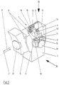
- An electrical switch 1 for regulating the speed of electric motors which is used in particular in electric hand tools with clockwise and anti-clockwise rotation, such as drills, rotary hammers, and the like. the like, is used, is shown schematically in Fig. 1.
- the switch 1 has a switch housing 2, in which a circuit board 3 is arranged.
- the electrical and electronic components 4 of a circuit arrangement for the speed control of the electric motor are located on the printed circuit board 3.
- This circuit arrangement can be a phase control which is known per se, as described, for example, in DE-OS 3219476.
- the switch 1 shown in FIG. 1 also has an actuating element designed as a pusher 5, which is adjustably mounted on the switch housing 2, and an actuating plunger 6 attached to it and leading into the interior of the switch 1.
- the pusher 5 can be moved manually in the direction of the arrow 7 'are moved against a compression spring, not shown, so that it returns to the starting position according to arrow 7 after release.
- the switch 1 there is a contact rocker 8, by means of which an electrical contact is made when the push button 5 is actuated.
- a switching cam 9 located on the actuating plunger 6 acts on one end 10 of the contact rocker 8, so that the contact connection between the other end 10 'of the contact rocker 8 and the connection contact 11 is opened.
- the switching cam 9 releases the end 10 of the contact rocker 8 and a tension spring 12 pulls the other end 10 'of the contact rocker 8 to the connection contact 11, so that the electrical connection is now closed.
- an extension 13 with a grinder 14 attached to it is arranged on the actuating plunger 6.
- One end of this grinder 14 slides on a resistance track 15 located on the printed circuit board 3, with which the grinder 14 and the resistance track 15 form a potentiometer 16.
- the electrical resistance corresponding to the respective position of the potentiometer 16, which is thus correlated to the respective position of the push button 5, is used for speed adjustment and control of the electric motor by means of the circuit arrangement located on the printed circuit board 3.
- the respective speed of the electric motor is dependent on the position of the pusher 5 and can be set up to a maximum speed, which corresponds to the maximum possible displacement of the pusher 5 in the direction 7 'and at which the full voltage is applied to the electric motor.
- a preselectable maximum speed which is on the one hand less than or equal to the maximum speed and on the other hand greater than or equal to a minimum speed depending on the switch design.
- This can be the case with drilling machines, for example in screwdriver operation, where the speed when screwing on is increased from zero to a preselected greatest speed, the preselected greatest speed depending on the material of the workpiece, the size of the screw and the like.
- the electrical switch 1 has a device for presetting a maximum speed, which is between the minimum and maximum speed.
- This device for presetting a maximum speed has an adjusting wheel 21 which is rotatably mounted on the front of the pusher 5 and which allows the maximum speed to be preselected by means of a rotary setting.
- the adjusting wheel 21 can be used to linearly adjust a slide 22 provided with a stop cam 23, which is guided in a recess 26 on a lateral surface of the switch housing 2.
- a threaded screw 24 projecting into the inside of the pusher 5 is connected to the adjusting wheel 21 and engages in a threaded counterpart 25 of the pusher 22 located on the end of the pusher 22 facing the pusher 5.
- the slide 22 and thus also the stop cam 23 can then be adjusted in the direction of the arrows 7 and 7 'by rotating the adjusting wheel 21.
- the slide 22, which is connected to the pusher 5 via the threaded screw 24 and the threaded counterpart 25, is also moved in the direction of the arrow 28 in the recess 26.
- the pusher 5 can then be moved until the stop cam 23 comes to rest against the front surface 44 of the switch housing 2. In this position, the electric motor runs at the highest speed selected by the setting wheel 21.
- the trigger 5 can run through the full adjustment path when actuated until the stop cam 23 comes to rest comes to the front surface 44 of the switch housing 2.
- the preselected highest speed is thus the maximum speed.
- the stop cam 23 is set with the help of the adjusting wheel 21 away from the inner surface of the pusher 5 in the direction of the switch housing 2, then the pusher 5 can only part of its full adjustment path until the stop cam 23 abuts the front surface 44 of the switch housing Run through 2 so that the preselected highest speed is less than the maximum speed.
- the minimum speed that can be set with the setting wheel 21 is consequently determined by the extent to which the stop cam 23 can be set in the direction of the switch housing 2 by means of the setting wheel 21.
- the electrical switch 1 also has a locking device for mechanically locking the actuating member in the position which corresponds to the preselected highest speed.
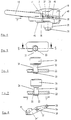
- the locking device consists of a locking lever 30 shown in greater detail in FIGS. 2 and 3, which cooperates with the slide 22, and a guide sleeve 29.
- the guide sleeve 29 is arranged on the side surface 45 of the switch housing 2 in the region of the end of the recess 26 facing the pusher 5 such that it engages over the recess 26, as a result of which the slide 22 can be moved freely in the recess 26 by the guide sleeve 29.
- the locking pusher 30 is movably mounted in the guide sleeve 29 against the force of a compression spring, not shown, in the direction perpendicular to the side surface 45 of the switch housing 2 and has a mandrel 32 facing the recess 26, which ends in a thickened end 33, as shown in FIGS 6 and 7 can be seen.
- the slide 22 is in turn provided with a recess 31, which is located in the region of the guide sleeve 29 when the pusher 5 is moved up to the maximum speed preselected by means of the adjusting wheel 21.
- the mandrel 32 can engage in the recess 31 by pressing in the locking lever 30, which is shown in FIGS. 5 and 6. If the pusher 5 is now released, it tries to move back with the slide 22 due to the spring pressure in the direction of the arrow 7, but the thickened end 33 hooks into the recess 31, as can be seen in more detail in FIG. 7, and so the further movement of the push button 5 ends. In this position, the pusher 5 then remains locked and the electric motor runs at the preselected highest speed without the pusher 5 having to be held manually.
- the pusher 5 is pressed again in the direction of the arrow 7 ', the slide 22 likewise moving in the direction of the arrow 7' according to FIG. 7, which is possible because the recess 31 is dimensioned larger than the size of the mandrel 32 by an appropriate overtravel 35. Due to the spring pressure exerted on the locking lever 30, the thickened end 33 jumps out of the recess 31, whereby the locking is released so that the lever 5 can be freely moved back in the direction of the arrow 7 (see FIG. 1 or 2).
- a changeover switch 18 for the right-left running of the electric motor is also latched, as can be seen in more detail in FIG. 2.
- This switch 18 has a switch lever 19 which protrudes slightly above the pusher 5.
- the switch lever 19 can be moved in two positions, namely in a first for clockwise rotation and in a second for counterclockwise rotation.
- the circuit to the electric motor is connected via leads which are connected to the plug contacts 20 so that the electric motor runs on the right or left.
- the brushes of the electric motors which are used in particular in electric hand tools, are generally set for the clockwise rotation from the neutral position in a preferred direction, which increases the torque in the clockwise rotation. However, this reduces the power that can be achieved in counterclockwise rotation without overloading the electric motor.
- the electrical switch 1 also has a device for limiting the speed in the counterclockwise rotation to a speed that is less than the maximum speed is, namely usually to a speed that is approximately half of the maximum speed. This device has a stroke limit stop 36 which is fastened inside the pusher 5.
- the device for preventing locking in counterclockwise rotation Integrated in this device for limiting the speed in counterclockwise rotation is the device for preventing locking in counterclockwise rotation.
- the stroke limit stop 36 and the stop cam 23 in counterclockwise rotation cooperate with the corresponding stops on the device for preventing locking in the counterclockwise rotation, which consist of a protruding projection 42 and a stop pin 43, as will be explained in more detail below, so that the The largest possible adjustment path of the pusher 5 in the counterclockwise rotation is preferably limited to approximately half the maximum possible adjustment path in the clockwise rotation. Consequently, a reduction in the maximum speed in counterclockwise rotation is achieved.
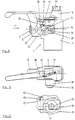
- the device for preventing locking in the counterclockwise rotation consists of a lever 37 which is rotatably mounted in a recess 40 on the top 17 of the switch housing 2 by means of a pin 38 engaging in a hole in the switch housing 2.
- a pin can of course also be attached to the top 17 of the switch housing 2 and this pin can engage in a hole in the lever 37.
- the lever 37 has two lever arms running parallel to the upper side 17 of the switch housing 2 in the recess 40, the first lever arm 34 in the direction facing away from the handle 5 and the second lever arm 34 'in the direction facing towards the handle 5 is arranged (see also Fig. 8).
- the second lever arm 34 ′ of the lever 37 ends on the side opposite the pin 38 approximately at the front edge of the switch housing 2. At this end an arm 41 extends approximately 90 degrees and runs parallel to the front surface 44 of the switch housing 2 (see also also Fig. 2).
- This arm 41 has a protruding projection 42, which is located approximately at the same height as the stroke limitation stop 36 and extends essentially parallel to the second lever arm 34 ′ of the lever 37.
- the approximately rectangular cross section of the angled arm 41 forms an angle ⁇ with the second lever arm 34 'of the lever 37, as can be seen in FIG. 8. This is preferably located Angle ⁇ at approximately 120 to 150 degrees. This has the advantage that the angled arm 41 in the counterclockwise position with its surface facing the switch housing 2 lies against the entire front surface of the switch housing 2 and can be supported there (compare FIGS. 2 and 3).
- the changeover switch 18 is in the counterclockwise direction and the adjusting wheel 21 is preset to one extreme position, namely maximum speed, as a result of which the stop cam 23 on the slide 22 is in its position closest to the pusher 5. If the pusher 5 is now moved according to the direction arrow 7 ', the stroke limit stop 36 comes into contact with the protruding shoulder 42 of the lever 37. As a result, the pusher 5 can no longer be moved and the greatest speed that can be set by actuating the pusher 5 becomes Counterclockwise rotation is limited to a lower speed than the maximum speed.
- the size of the stroke limit stop 36 and the protruding shoulder 42 is selected so that this maximum adjustable speed in the left-hand rotation is approximately half the maximum speed.
- the size of the stop pin 43 will preferably be selected so that on the one hand the minimum speed is only slightly reduced in the counterclockwise rotation and on the other hand one Engagement of the thickened end 33 in the recess 31 is just not possible. In this way, even with a pre-selected minimum speed, an effective prevention of locking in the left-hand rotation is achieved.
- the thickened end 33 of the mandrel 32 of the locking lever 30 can engage in the recess 31 on the slide 22 in none of these positions, so that the locking device engages in all presettable positions of the adjusting wheel 21 in the counterclockwise rotation is prevented.
- the locking device engages in all presettable positions of the adjusting wheel 21 in the counterclockwise rotation is prevented.
- the size of the stroke limit stop 36 is coordinated with the protruding shoulder 42 for counterclockwise rotation so that the stroke limit stop 36 does not yet touch the front surface of the switch housing 2 or at most just touches it when the trigger 5 is set for maximum speed in clockwise rotation. A reduction in the speed due to the stroke limit stop 36 can therefore not occur in clockwise rotation and the maximum adjustment path of the pusher 5 is only determined by the abutment cam 23 resting on the front surface 44 of the switch housing 2, as already described above.
Landscapes
- Rotary Switch, Piano Key Switch, And Lever Switch (AREA)
- Push-Button Switches (AREA)
- Mechanical Control Devices (AREA)
- Combined Controls Of Internal Combustion Engines (AREA)
Claims (24)
- Commutateur électrique (1) pour régler la vitesse de moteurs, en particulier de moteurs électriques sur des outils à main électriques, comportant un organe d'actionnement (5) monté de façon réglable sur un boîtier de commutateur, une vitesse de rotation correspondant à la position de l'organe d'actionnement étant réglée sur le moteur au moyen d'un circuit avantageusement électronique, comportant un dispositif pour le réglage préalable d'une vitesse la plus grande, qui est inférieure ou égale à une vitesse maximale et supérieure ou égale à une vitesse minimale, un dispositif d'arrêt, qui permet l'arrêt de l'organe d'actionnement (5) dans la position correspondant à la plus grande vitesse préréglée, un inverseur (18) pour la marche à droite ou à gauche du moteur,
caractérisé par un dispositif pour limiter la vitesse dans la marche à gauche à une vitesse qui est inférieure à la vitesse maximale, et un dispositif, agencé sur le commutateur (1), pour empêcher l'arrêt dans la marche à gauche, le dispositif pour empêcher l'arrêt dans la marche à gauche, pour un inverseur (18) se trouvant sur la marche à gauche, coopérant avec le dispositif pour limiter la vitesse dans la marche à gauche et/ou avec le dispositif pour le réglage préalable d'une vitesse la plus grande. - Commutateur électrique selon la revendication 1,
caractérisé en ce que le dispositif pour empêcher l'arrêt dans la marche à gauche est intégré dans le dispositif pour limiter la vitesse dans la marche à gauche. - Commutateur électrique selon la revendication 1 ou 2,
caractérisé en ce que le dispositif pour limiter la vitesse dans la marche à gauche est constitué d'une butée de limitation de course (36) se trouvant sur l'organe d'actionnement (5). - Commutateur électrique selon la revendication 1, 2 ou 3,
caractérisé en ce que le dispositif pour le réglage préalable d'une vitesse la plus grande est constitué d'un coulisseau (22) agencé de façon réglable sur l'organe d'actionnement (5), sur lequel est agencé un ergot de butée (23) coopérant avec la face avant (44) du boîtier de commutateur (2). - Commutateur électrique selon la revendication 4,
caractérisé en ce que le coulisseau (22) présente un évidement (31) et le dispositif d'arrêt un poussoir d'arrêt (30) ayant une broche (32), qui s'engage, lors de l'arrêt, dans l'évidement (31), de sorte que l'extrémité épaissie (33) de la broche (32) s'enclenche dans l'évidement (31). - Commutateur électrique selon une des revendications 1 à 5,
caractérisé en ce que le dispositif pour empêcher l'arrêt dans la marche à gauche est actionné par l'inverseur (18) pour la marche à droite ou à gauche. - Commutateur électrique selon la revendication 6,
caractérisé en ce que le dispositif pour empêcher l'arrêt dans la marche à gauche est constitué d'un levier (37), qui possède des butées qui coopèrent, dans la marche à gauche, avec la butée de limitation de course (36) ou avec l'ergot de butée (23) du coulisseau (22). - Commutateur électrique selon la revendication 7,
caractérisé en ce que le levier (37) peut pivoter, au moyen d'un levier d'inversion (19) sur l'inverseur (18), entre une position de marche à droite et une position de marche à gauche, qui sont associées, à chaque fois, à un des côtés opposés l'un à l'autre du boîtier (2) du commutateur. - Commutateur électrique selon la revendication 7 ou 8,
caractérisé en ce que la butée de limitation de course (36) et le coulisseau (22) avec l'ergot de butée (23) sont agencés de façon asymétrique par rapport à l'axe central (48) du boîtier (2) du commutateur sur le côté du boîtier (2) du commutateur associé à la position de marche à gauche. - Commutateur électrique selon une des revendications 7 à 9,
caractérisé en ce que le levier (37) est monté de façon rotative au moyen d'un tourillon (38) sur le boîtier (2) du commutateur. - Commutateur électrique selon la revendication 10,
caractérisé en ce que le tourillon (38) est agencé sur le levier (37) et s'engage dans un trou sur la face supérieure (17) du boîtier (2) du commutateur, sur laquelle repose une surface de l'inverseur (19) pour la marche à droite ou à gauche. - Commutateur électrique selon la revendication 10,
caractérisé en ce que le tourillon est agencé sur la face supérieure (17) du boîtier (2) du commutateur, sur laquelle repose une surface de l'inverseur (19) pour la marche à droite ou à gauche, et s'engage dans un trou dans le levier (37). - Commutateur électrique selon la revendication 11 ou 12,
caractérisé en ce que le levier (37) est agencé dans une cavité (40) sur la face supérieure (17) du boîtier (2) du commutateur. - Commutateur électrique selon une des revendications 7 à 13,
caractérisé en ce que le levier (37) présente un premier bras de levier (34), opposé à l'organe d'actionnement (5), s'étendant parallèlement à la face supérieure (17) du boîtier (2) du commutateur, bras de levier sur lequel se trouve un ergot (39) qui coopère avec l'inverseur (18). - Commutateur électrique selon la revendication 14,
caractérisé en ce que l'ergot (39) se trouvant sur le premier bras de levier (34) s'engage dans un trou oblong (46) sur le levier d'inversion (19) de l'inverseur (18). - Commutateur électrique selon une des revendications 7 à 13,
caractérisé en ce que le levier d'inversion (19) de l'inverseur (18) présente un ergot qui coopère avec le premier bras de levier (34) du levier (37), opposé à l'organe d'actionnement (5) et s'étendant parallèlement à la face supérieure (17) du boîtier (2) du commutateur. - Commutateur électrique selon la revendication 16,
caractérisé en ce que l'ergot se trouvant sur le levier d'inversion (19) s'engage dans un trou oblong sur le premier bras de levier (34). - Commutateur électrique selon une des revendications 14 à 17,
caractérisé en ce que le levier (37) présente un second bras de levier (34'), en regard de l'organe d'actionnement (5), s'étendant parallèlement à la face supérieure (17) du boîtier (2) du commutateur, bras de levier sur l'extrémité opposée au tourillon (38) duquel se trouve un bras (41) s'étendant parallèlement à la face avant (44) du boîtier (2) du commutateur et coudé sensiblement à 90°. - Commutateur électrique selon la revendication 18,
caractérisé en ce que les butées se trouvant sur le levier (37), qui coopèrent dans la marche à gauche avec la butée de limitation de course (36) ou avec l'ergot de butée (23) du coulisseau (22), sont agencées sur le bras coudé (41). - Commutateur électrique selon la revendication 19,
caractérisé en ce qu'une saillie (42) et un tourillon de butée (43) se trouvent sur l'arbre coudé (41), la saillie (42) coopérant avec la butée de limitation de course (36) et le tourillon de butée (43) coopérant avec l'ergot de butée (23) sur le coulisseau (22). - Commutateur électrique selon une des revendications 18 à 20,
caractérisé en ce que le bras coudé (41) présente une section transversale sensiblement rectangulaire, qui, avec le second bras de levier (34') du levier (37), forme un angle α tel que la surface, en regard du boîtier (2) du commutateur, du bras coudé (41) repose, dans la position pour la marche à gauche, sur toute sa surface, sur la face avant du boîtier (2) du commutateur et s'y appuie. - Commutateur électrique selon la revendication 21,
caractérisé en ce que l'angle α vaut entre 120 et 150 degrés. - Commutateur électrique selon une des revendications 20 à 22,
caractérisé en ce que la taille de la butée de limitation de course (36) et de la saillie (42) est choisie de sorte que la vitesse de rotation la plus grande, réglable à l'aide de l'organe d'actionnement (5), est diminuée dans la marche à gauche à une vitesse qui correspond sensiblement à la moitié de la vitesse maximale. - Commutateur électrique selon une des revendications 20 à 23,
caractérisé en ce que la taille du tourillon de butée (43) est choisie de sorte que, d'une part, la vitesse minimale est réduite seulement un peu dans la marche à gauche et que, d'autre part, même pour une vitesse minimale préalablement choisie, un empêchement effectif de l'arrêt dans la marche à gauche est obtenu.
Applications Claiming Priority (2)
| Application Number | Priority Date | Filing Date | Title |
|---|---|---|---|
| DE4225287A DE4225287A1 (de) | 1992-07-31 | 1992-07-31 | Elektrischer Schalter zur Drehzahlregulierung von Motoren |
| DE4225287 | 1992-07-31 |
Publications (3)
| Publication Number | Publication Date |
|---|---|
| EP0585541A2 EP0585541A2 (fr) | 1994-03-09 |
| EP0585541A3 EP0585541A3 (fr) | 1994-11-17 |
| EP0585541B1 true EP0585541B1 (fr) | 1997-09-10 |
Family
ID=6464521
Family Applications (1)
| Application Number | Title | Priority Date | Filing Date |
|---|---|---|---|
| EP93108632A Expired - Lifetime EP0585541B1 (fr) | 1992-07-31 | 1993-05-28 | Commutateur électrique à réglage de vitesse des moteurs |
Country Status (3)
| Country | Link |
|---|---|
| EP (1) | EP0585541B1 (fr) |
| DE (2) | DE4225287A1 (fr) |
| ES (1) | ES2110026T3 (fr) |
Cited By (4)
| Publication number | Priority date | Publication date | Assignee | Title |
|---|---|---|---|---|
| US11491616B2 (en) | 2015-06-05 | 2022-11-08 | Ingersoll-Rand Industrial U.S., Inc. | Power tools with user-selectable operational modes |
| US11602832B2 (en) | 2015-06-05 | 2023-03-14 | Ingersoll-Rand Industrial U.S., Inc. | Impact tools with ring gear alignment features |
| US11707831B2 (en) | 2015-06-05 | 2023-07-25 | Ingersoll-Rand Industrial U.S., Inc. | Power tool housings |
| US11784538B2 (en) | 2015-06-05 | 2023-10-10 | Ingersoll-Rand Industrial U.S., Inc. | Power tool user interfaces |
Families Citing this family (6)
| Publication number | Priority date | Publication date | Assignee | Title |
|---|---|---|---|---|
| DE4410312C2 (de) * | 1994-03-25 | 2000-01-13 | Bosch Gmbh Robert | Elektrische Handwerkzeugmaschine mit Potentiometer und Verfahren zum Einstellen des Potentiometers |
| DE4445339A1 (de) * | 1994-12-19 | 1996-06-20 | Kopp Heinrich Ag | Vorrichtung für das Schalten eines Elektromotors, insbesondere zum Abbremsen eines Elektrowerkzeuges |
| DE19635102B4 (de) * | 1996-08-30 | 2006-01-19 | Marquardt Gmbh | Elektrischer Schalter |
| DE10334884A1 (de) * | 2003-07-29 | 2005-03-10 | Alexander Muehlhaeuser | Schaltelement für die Drehrichtungs- und Drehzahlwahl von Elektrohandwerksmaschinen insbesondere Akkubohrmaschinen |
| CN107635725B (zh) | 2015-06-05 | 2019-11-12 | 英古所连公司 | 用于电动工具的照明系统 |
| WO2016196891A1 (fr) | 2015-06-05 | 2016-12-08 | Ingersoll-Rand Company | Interfaces utilisateur de machine-outil électrique |
Family Cites Families (6)
| Publication number | Priority date | Publication date | Assignee | Title |
|---|---|---|---|---|
| US297744A (en) * | 1884-04-29 | Cuff-holder | ||
| US3781579A (en) * | 1973-01-03 | 1973-12-25 | Black & Decker Mfg Co | Protected lock means for electrically-operated,hand-manipulated tools |
| DE2629722C3 (de) * | 1976-07-02 | 1981-04-23 | Scintilla Ag, Solothurn | Handbetätigbare Einbauschaltvorrichtung für elektrische Maschinen, insbesondere Handbohrmaschinen |
| DE2755960A1 (de) * | 1977-12-15 | 1979-06-21 | Licentia Gmbh | Motorisch angetriebenes heimwerkergeraet |
| DE3342412A1 (de) * | 1983-11-24 | 1985-06-05 | Black & Decker Inc., Newark, Del. | Schalteranordnung fuer den drehrichtungsumschalter eines elektrowerkzeugs, insbesondere einer bohr- oder schlagbohrmaschine |
| DE4006466A1 (de) * | 1990-03-01 | 1991-09-05 | Black & Decker Inc | Schalter |
-
1992
- 1992-07-31 DE DE4225287A patent/DE4225287A1/de not_active Withdrawn
-
1993
- 1993-05-28 DE DE59307318T patent/DE59307318D1/de not_active Expired - Lifetime
- 1993-05-28 EP EP93108632A patent/EP0585541B1/fr not_active Expired - Lifetime
- 1993-05-28 ES ES93108632T patent/ES2110026T3/es not_active Expired - Lifetime
Cited By (4)
| Publication number | Priority date | Publication date | Assignee | Title |
|---|---|---|---|---|
| US11491616B2 (en) | 2015-06-05 | 2022-11-08 | Ingersoll-Rand Industrial U.S., Inc. | Power tools with user-selectable operational modes |
| US11602832B2 (en) | 2015-06-05 | 2023-03-14 | Ingersoll-Rand Industrial U.S., Inc. | Impact tools with ring gear alignment features |
| US11707831B2 (en) | 2015-06-05 | 2023-07-25 | Ingersoll-Rand Industrial U.S., Inc. | Power tool housings |
| US11784538B2 (en) | 2015-06-05 | 2023-10-10 | Ingersoll-Rand Industrial U.S., Inc. | Power tool user interfaces |
Also Published As
| Publication number | Publication date |
|---|---|
| DE4225287A1 (de) | 1994-02-03 |
| ES2110026T3 (es) | 1998-02-01 |
| EP0585541A2 (fr) | 1994-03-09 |
| EP0585541A3 (fr) | 1994-11-17 |
| DE59307318D1 (de) | 1997-10-16 |
Similar Documents
| Publication | Publication Date | Title |
|---|---|---|
| EP1070331B1 (fr) | Interrupteur electrique | |
| DE3112097C2 (de) | "Sicherheitsschalter" | |
| DE4407418C2 (de) | Schalteranordnung, insbesondere für eine Oberfräse | |
| EP3439011A1 (fr) | Appareil électrique | |
| EP0585541B1 (fr) | Commutateur électrique à réglage de vitesse des moteurs | |
| DE3342474C2 (fr) | ||
| DE102006007600B4 (de) | Drehsteller für elektrische oder elektronische Gräte in einem Kraftfahrzeug | |
| DE69228001T2 (de) | Sicherheitsschalter für arbeitsmaschinen | |
| DE3815883C2 (fr) | ||
| DE3512665C2 (de) | Elektrischer Schalter | |
| DE2717114A1 (de) | Antrieb mit hilfsschalter fuer einen elektrisch verriegelbaren leistungsschalter | |
| EP0184652A2 (fr) | Interrupteur avec coupe-circuit | |
| EP3321160B1 (fr) | Émetteur manuel | |
| DE3442173A1 (de) | Elektrischer schalter gedrungener bauart | |
| DE60003821T2 (de) | Motorischer Antrieb | |
| DE69501990T2 (de) | Drehschalter mit verriegelbarer Position | |
| DE19934542C1 (de) | Schaltersicherungseinheit mit Halterverriegelung | |
| DE69105776T2 (de) | Schalter. | |
| EP1253994A1 (fr) | Dispositif de serrage | |
| DE102005015399B3 (de) | Schaltersicherungseinheit | |
| DE2445632B2 (de) | Einstellvorrichtung für einen elektromagnetischen Auslöser | |
| DE20201230U1 (de) | Vorrichtung zum Einstellen der Banddicke für eine tragbare Packmaschine | |
| DE3145629C2 (fr) | ||
| DE20107583U1 (de) | Schalter sowie Elektrohandwerkzeug | |
| EP0071207A2 (fr) | Interrupteur électrique rotatif avec un axe de positionnement actionné en rotation et en coulissement axial par un organe de commande |
Legal Events
| Date | Code | Title | Description |
|---|---|---|---|
| PUAI | Public reference made under article 153(3) epc to a published international application that has entered the european phase |
Free format text: ORIGINAL CODE: 0009012 |
|
| AK | Designated contracting states |
Kind code of ref document: A2 Designated state(s): CH DE ES FR GB IT LI NL |
|
| PUAL | Search report despatched |
Free format text: ORIGINAL CODE: 0009013 |
|
| AK | Designated contracting states |
Kind code of ref document: A3 Designated state(s): CH DE ES FR GB IT LI NL |
|
| 17P | Request for examination filed |
Effective date: 19950218 |
|
| 17Q | First examination report despatched |
Effective date: 19960530 |
|
| GRAG | Despatch of communication of intention to grant |
Free format text: ORIGINAL CODE: EPIDOS AGRA |
|
| GRAH | Despatch of communication of intention to grant a patent |
Free format text: ORIGINAL CODE: EPIDOS IGRA |
|
| GRAH | Despatch of communication of intention to grant a patent |
Free format text: ORIGINAL CODE: EPIDOS IGRA |
|
| GRAA | (expected) grant |
Free format text: ORIGINAL CODE: 0009210 |
|
| AK | Designated contracting states |
Kind code of ref document: B1 Designated state(s): CH DE ES FR GB IT LI NL |
|
| PG25 | Lapsed in a contracting state [announced via postgrant information from national office to epo] |
Ref country code: GB Free format text: LAPSE BECAUSE OF FAILURE TO SUBMIT A TRANSLATION OF THE DESCRIPTION OR TO PAY THE FEE WITHIN THE PRESCRIBED TIME-LIMIT Effective date: 19970910 Ref country code: FR Free format text: LAPSE BECAUSE OF FAILURE TO SUBMIT A TRANSLATION OF THE DESCRIPTION OR TO PAY THE FEE WITHIN THE PRESCRIBED TIME-LIMIT Effective date: 19970910 |
|
| REG | Reference to a national code |
Ref country code: CH Ref legal event code: EP |
|
| REF | Corresponds to: |
Ref document number: 59307318 Country of ref document: DE Date of ref document: 19971016 |
|
| REG | Reference to a national code |
Ref country code: CH Ref legal event code: NV Representative=s name: KELLER & PARTNER PATENTANWAELTE AG |
|
| ITF | It: translation for a ep patent filed | ||
| REG | Reference to a national code |
Ref country code: ES Ref legal event code: FG2A Ref document number: 2110026 Country of ref document: ES Kind code of ref document: T3 |
|
| EN | Fr: translation not filed | ||
| GBV | Gb: ep patent (uk) treated as always having been void in accordance with gb section 77(7)/1977 [no translation filed] |
Effective date: 19970910 |
|
| PLBE | No opposition filed within time limit |
Free format text: ORIGINAL CODE: 0009261 |
|
| STAA | Information on the status of an ep patent application or granted ep patent |
Free format text: STATUS: NO OPPOSITION FILED WITHIN TIME LIMIT |
|
| 26N | No opposition filed | ||
| PGFP | Annual fee paid to national office [announced via postgrant information from national office to epo] |
Ref country code: NL Payment date: 20090527 Year of fee payment: 17 Ref country code: ES Payment date: 20090521 Year of fee payment: 17 |
|
| PGFP | Annual fee paid to national office [announced via postgrant information from national office to epo] |
Ref country code: IT Payment date: 20090527 Year of fee payment: 17 |
|
| PGFP | Annual fee paid to national office [announced via postgrant information from national office to epo] |
Ref country code: CH Payment date: 20090519 Year of fee payment: 17 |
|
| REG | Reference to a national code |
Ref country code: NL Ref legal event code: V1 Effective date: 20101201 |
|
| REG | Reference to a national code |
Ref country code: CH Ref legal event code: PL |
|
| PG25 | Lapsed in a contracting state [announced via postgrant information from national office to epo] |
Ref country code: LI Free format text: LAPSE BECAUSE OF NON-PAYMENT OF DUE FEES Effective date: 20100531 Ref country code: CH Free format text: LAPSE BECAUSE OF NON-PAYMENT OF DUE FEES Effective date: 20100531 |
|
| PG25 | Lapsed in a contracting state [announced via postgrant information from national office to epo] |
Ref country code: IT Free format text: LAPSE BECAUSE OF NON-PAYMENT OF DUE FEES Effective date: 20100528 Ref country code: NL Free format text: LAPSE BECAUSE OF NON-PAYMENT OF DUE FEES Effective date: 20101201 |
|
| REG | Reference to a national code |
Ref country code: ES Ref legal event code: FD2A Effective date: 20110715 |
|
| PG25 | Lapsed in a contracting state [announced via postgrant information from national office to epo] |
Ref country code: ES Free format text: LAPSE BECAUSE OF NON-PAYMENT OF DUE FEES Effective date: 20110705 |
|
| PG25 | Lapsed in a contracting state [announced via postgrant information from national office to epo] |
Ref country code: ES Free format text: LAPSE BECAUSE OF NON-PAYMENT OF DUE FEES Effective date: 20100529 |
|
| PGFP | Annual fee paid to national office [announced via postgrant information from national office to epo] |
Ref country code: DE Payment date: 20120605 Year of fee payment: 20 |
|
| REG | Reference to a national code |
Ref country code: DE Ref legal event code: R071 Ref document number: 59307318 Country of ref document: DE |
|
| PG25 | Lapsed in a contracting state [announced via postgrant information from national office to epo] |
Ref country code: DE Free format text: LAPSE BECAUSE OF EXPIRATION OF PROTECTION Effective date: 20130529 |