EP0199990A1 - Schaltungsanordnung zur Erzeugung eines Impulses bestimmter Dauer - Google Patents
Schaltungsanordnung zur Erzeugung eines Impulses bestimmter Dauer Download PDFInfo
- Publication number
- EP0199990A1 EP0199990A1 EP86104102A EP86104102A EP0199990A1 EP 0199990 A1 EP0199990 A1 EP 0199990A1 EP 86104102 A EP86104102 A EP 86104102A EP 86104102 A EP86104102 A EP 86104102A EP 0199990 A1 EP0199990 A1 EP 0199990A1
- Authority
- EP
- European Patent Office
- Prior art keywords
- pulse
- constant current
- current source
- capacitor
- switches
- Prior art date
- Legal status (The legal status is an assumption and is not a legal conclusion. Google has not performed a legal analysis and makes no representation as to the accuracy of the status listed.)
- Granted
Links
- 239000003990 capacitor Substances 0.000 claims abstract description 15
- 230000001960 triggered effect Effects 0.000 claims abstract description 3
- 230000001360 synchronised effect Effects 0.000 description 2
- 238000010586 diagram Methods 0.000 description 1
- 230000010355 oscillation Effects 0.000 description 1
- 239000010453 quartz Substances 0.000 description 1
- VYPSYNLAJGMNEJ-UHFFFAOYSA-N silicon dioxide Inorganic materials O=[Si]=O VYPSYNLAJGMNEJ-UHFFFAOYSA-N 0.000 description 1
Images

Classifications
-
- H—ELECTRICITY
- H03—ELECTRONIC CIRCUITRY
- H03K—PULSE TECHNIQUE
- H03K5/00—Manipulating of pulses not covered by one of the other main groups of this subclass
- H03K5/01—Shaping pulses
- H03K5/04—Shaping pulses by increasing duration; by decreasing duration
- H03K5/05—Shaping pulses by increasing duration; by decreasing duration by the use of clock signals or other time reference signals
Definitions
- the invention is based on a circuit arrangement for generating a pulse of a certain duration triggered by a trigger pulse.
- a pulse of constant duration For example, monostable flip-flops are known which are tipped by a trigger pulse into a position providing an output pulse, after which they automatically tip back into their starting position after a time measured by an RC element.
- flip-flops only deliver a pulse duration that is within the component tolerances of the time constant element. If exactly defined pulse lengths are required, such flip-flops are not suitable.
- Time constant measuring devices are also known, with which the time constants of RC elements can be determined. These have an oscillator, which can be very precise when using a quartz.
- a bistable flip-flop which is set by the trigger pulse and defines the start of the pulse to be generated, also defines the Vibrations of the oscillator at the input of a counter, which resets the bistable multivibrator after a predetermined number of pulses l, thereby determining the end of the pulse to be generated.
- the invention has for its object to generate a pulse of constant and certain length. This object is achieved by the invention specified in the patent claim.
- the invention has the advantage that the trigger pulse does not have to be synchronous with the oscillator, so that the start of the pulse to be generated is determined solely by the trigger pulse.
- a pulse of a certain duration is e.g. needed to control the line end transistor in television sets. It is also used in circuits to precisely determine a frequency.
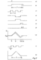
- a bistable flip-flop 1 is set by a trigger pulse S (FIG. 2a), so that H potential arises at the outputs Q1 and Q2 (FIG. 2b).
- the output Q1 switches through a gate circuit 2 so that the pulses generated by a pulse generator 3 can reach the clock input C of a frequency divider 4.
- a switch contact 9 is opened at the start of charging.
- a voltage UC builds up on the capacitor 8 (FIG. 2h), when the first pulse from the pulse generator 3 arrives, the Q output of the divider 4 goes to H potential (FIG. 2e) and switches on the constant current source 10, which also carries the capacitor 8 discharges the current I2 from t2 to t3 ( Figure 2h).
- the first constant current source 7 is now switched off. After the duration t of a period of the pulse generator 3, the second constant current source 10 is switched off and the first constant current source 7 is switched on again.
- the charging current I1 flows again from t3 to t4 and the voltage UC increases until the reference voltage U ref is reached.
- FIG. 2h shows how the pulse duration T can be changed by setting the ratios of the two currents I1 to I2.
- T (1 + I2 / I1) t with the limits for I2: 0.9 I1 ⁇ I2 ⁇ 1.8 11.
- pulse generator 3 If a longer pulse duration is required, this can be generated by interposing a divider between pulse generator 3 and gate circuit.
- Fig. 2 i, k shows that the duration T of the generated pulse is independent of the phase relationship between the trigger pulse S and the generator pulse.
- 2 i shows a generator signal which is phase-shifted with respect to FIG. 2 c.
- Figure 2k shows the associated voltage curve Uc, which delivers the same pulse duration T.
Landscapes
- Physics & Mathematics (AREA)
- Nonlinear Science (AREA)
- Pulse Circuits (AREA)
- Manipulation Of Pulses (AREA)
- Stabilization Of Oscillater, Synchronisation, Frequency Synthesizers (AREA)
Abstract
Description
- Die Erfindung geht aus von einer Schaltungsanordnung zur Erzeugung eines durch einen Triggerimpuls ausgelösten Impulses bestimmter Dauer.
- Zur Erzeugung eines Impulses konstanter Dauer . sind z.B. monostabile Kippstufen bekannt, die durch einen Triggerimpuls in eine einen Ausgangsimpuls liefernde Lage gekippt werden, wonach sie automatisch nach einer durch ein RC-Glied bemessenen Zeit wieder in ihre Ausgangslage zurückkippen. Derartige Kippschaltungen liefern jedoch nur eine im Rahmen der Bauteiletoleranzen des Zeitkonstantengliedes liegende Impulsdauer. Werden genau definierte Impulslängen gefordert, sind derartige Kippschaltungen nicht geeigent. Es sind auch Zeitkonstantenmeßgeräte bekannt, mit denen man die Zeitkonstanten von RC-Gliedern ermitteln kann. Diese besitzen einen Oszillator, der bei Verwendung eines Quarzes sehr genau sein kann. Eine bistabile Kippstufe, die durch den Triggerimpuls gesetzt wird und den Beginn des zu erzeugenden Impulses festlegt, legt gleichzeitig die Schwingungen des Oszillators an den Eingang eines Zählers, der nach einer vorgegebenen Anzahl von Impulsen die bistabile Kippschaltung wieder zurücksetztl wodurch das Ende des zu erzeugenden Impulses festgelegt ist. Diese Schaltung besitzt zwar den Vorzug großer Genauigkeit ist jedoch mit dem Nachteil verbunden, daß der Triggerimpuls synchron mit den Oszillatorschwingungen sein muß, um ein genaues Zählergebnis zu erhalten.
- Der Erfindung liegt die Aufgabe zugrunde, einen Impuls konstanter und bestimmter Länge zu erzeugen. Diese Aufgabe wird durch die im Patentanspruch angegebene Erfindung gelöst. Die Erfindung besitzt den Vorteil, daß der Triggerimpuls nicht synchron mit dem Oszillator zu sein braucht, so daß der Beginn des zu erzeugenden Impulses allein vom Trigger- impuls bestimmt wird. Ein Impuls bestimmter Dauer wird z.B. zur Ansteuerung des Zeilenendtransistors in Fernsehgeräten benötigt. Er findet auch Anwendung in Schaltungen zur genauen Ermittlung einer Frequenz.
- Nachstehend wird das Prinzip der Erfindung an einem Ausführungsbeispiel mit Hilfe der Zeichnung erläutert.
-
- Figur 1 zeigt eine Schaltung zur Erzeugung eines Impulses definierter Länge;
- Figur 2 zeigt Diagramme zur Erläuterung der Wirkungsweise der Schaltung nach Figur 1.
- Zu Beginn wird durch einen Triggerimpuls S (Figur 2a) eine bistabile Kippstufe 1 gesetzt, so daß an den Ausgängen Ql und Q2 H-Potential entsteht (Figur 2b). Der Ausgang Ql schaltet eine Torschaltung 2 durch, so daß die von einem Impulsgenerator 3 erzeugten Impulse an den Clock-Eingang C eines Frequenzteilers 4 gelangen können. Der Ausgang Q2 der bistabilen Kippschaltung 1, an welchem das gewünschte Impulssignal definierter Länge entnehmbar ist, schaltet über einen Inverter 5 und ein NOR-Gatter 6 eine Konstantstromquelle 7 ein, welche einen Kondensator 8 mit dem Strom I1 während der Zeit von t1 bis t2 von einer Referenzspannung U ref ausgehend auflädt (Figur 2h). Zu Beginn der Ladung wird ein Schaltkontakt 9 geöffnet. Am Kondesator 8 baut sich eine Spannung UC auf (Figur 2h), bei Eintreffendes ersten Impulses aus dem Impulsgenerator 3 geht der Q-Ausgang des Teilers 4 auf H-Potential (Figur 2e) und schaltet die Konstantstromquelle 10 ein, die den Kondensator 8 mit dem Strom I2 von t2 bis t3 (Figur 2h) entlädt. Die erste Konstantstromquelle 7 ist jetzt abgeschaltet. Nach der Dauer t einer Periode des Impulsgenerators 3 wird die zweite Konstantstromquelle 10 ab- und die erste Konstantstromquelle 7 wieder eingeschaltet. Es fließt wieder der Ladestrom I1 von t3 bis t4 und die Spannung UC steigt an bis die Referenzspannung Uref erreicht ist. Die am Kondensator 8 liegende Spannung UC wird mit Hilfe einer Komparatorschaltung 11 mit der Referenzspannung Uref verglichen, so daß am Ausgang ein Signal entsteht (Figur 2g), welches die bistabile Kippschaltung 1 wieder zurücksetzt. Hiermit ist der Impuls beendet, der am Ausgang 12 zur Verfügung steht (Figur 2b). Damit die Komparatorschaltung 11 nur während der Zeit bis zum Erreichen der Referenzspannung arbeitet wird sie durch den Teiler 4 über eine bistabile Kippschaltung 13 aktiviert, die durch den Ausgangsimpuls der Komparatorschaltung 11 wieder zurückgesetzt wird (Figur 2f). In Figur 2h ist gezeigt, wie durch die Einstellung der Verhältnisse der beiden Ströme I1 zu I2 die Impulsdauer T veränderbar ist. Figur 2b, f, g, h zeigt den Fall für I1 = I2 (durchgezogene Linie) und für I1 = 0,75 I2 (ge- strichelte Linie).
- Für die Impulsdauer T ergibt sich rechnerisch aus den Strömen I1 und I2 sowie aus der Periodendauer t des Impulsgenerators 3:T = (1+I2/I1) t mit den Grenzen für I2: 0,9 I1 ≦ I2 ≼ 1,8 11.
- Ist eine längere Impulsdauer erforderlich, kann diese durch Zwischenschaltung eines Teilers zwischen Impulsgenerator 3 und Torschaltung erzeugt werden.
- Fig. 2 i, k zeigt, daß die Dauer T des erzeugten Impulses von der Phasenbeziehung zwischen dem Trigger- Impuls S und dem Generator-Impuls unabhängig ist. In Fig. 2 i ist ein gegenüber Fig. 2c phasenverschobenes Generator-Signal aufgetragen. Figur 2k zeigt den zugehörigen Spannungsverlauf Uc, der die gleiche Impulsdauer T liefert.
-
- 1 Kippschaltung
- 2 Torschaltung
- 3 Impulsgenerator
- 4 Frequenzteiler
- 5 Inverter
- 6 NOR-Gatter
- 7 Konstantstromquelle
- 8 Kondensator
- 9 Schaltkontakt
- 10 Konstantstromquelle
- 11 Komparatorschaltung
- 12 Ausgang
- 13 Kippschaltung
Claims (3)
Applications Claiming Priority (2)
| Application Number | Priority Date | Filing Date | Title |
|---|---|---|---|
| DE19853511842 DE3511842A1 (de) | 1985-03-30 | 1985-03-30 | Schaltungsanordnung zur erzeugung eines impulses bestimmter dauer |
| DE3511842 | 1985-03-30 |
Publications (2)
| Publication Number | Publication Date |
|---|---|
| EP0199990A1 true EP0199990A1 (de) | 1986-11-05 |
| EP0199990B1 EP0199990B1 (de) | 1990-06-13 |
Family
ID=6266972
Family Applications (1)
| Application Number | Title | Priority Date | Filing Date |
|---|---|---|---|
| EP86104102A Expired - Lifetime EP0199990B1 (de) | 1985-03-30 | 1986-03-25 | Schaltungsanordnung zur Erzeugung eines Impulses bestimmter Dauer |
Country Status (3)
| Country | Link |
|---|---|
| EP (1) | EP0199990B1 (de) |
| JP (1) | JPH0750855B2 (de) |
| DE (2) | DE3511842A1 (de) |
Families Citing this family (2)
| Publication number | Priority date | Publication date | Assignee | Title |
|---|---|---|---|---|
| JPH0322611A (ja) * | 1989-06-19 | 1991-01-31 | Nec Corp | パルス発生回路 |
| DE19531030A1 (de) * | 1995-08-23 | 1997-02-27 | Siemens Ag | Doppelimpuls-Generator, insbesondere für den Sendebetrieb auf einem EIB-Bus |
Citations (2)
| Publication number | Priority date | Publication date | Assignee | Title |
|---|---|---|---|---|
| DE3325646A1 (de) * | 1982-07-20 | 1984-01-26 | Sony Corp., Tokyo | Pulssignal-verarbeitungsschaltung |
| DE3310461A1 (de) * | 1983-03-23 | 1984-09-27 | Philips Patentverwaltung Gmbh, 2000 Hamburg | Verfahren und schaltungsanordnung zum erzeugen von impulsen |
Family Cites Families (3)
| Publication number | Priority date | Publication date | Assignee | Title |
|---|---|---|---|---|
| US3638045A (en) * | 1969-04-14 | 1972-01-25 | Us Navy | Pulse stretcher |
| US4082075A (en) * | 1976-02-27 | 1978-04-04 | Motorola, Inc. | Input quarter cycle timing circuit |
| US4282549A (en) * | 1979-12-11 | 1981-08-04 | Rca Corporation | Pulse generator for a horizontal deflection system |
-
1985
- 1985-03-30 DE DE19853511842 patent/DE3511842A1/de not_active Withdrawn
-
1986
- 1986-03-25 DE DE8686104102T patent/DE3672046D1/de not_active Expired - Fee Related
- 1986-03-25 EP EP86104102A patent/EP0199990B1/de not_active Expired - Lifetime
- 1986-03-31 JP JP61071395A patent/JPH0750855B2/ja not_active Expired - Lifetime
Patent Citations (2)
| Publication number | Priority date | Publication date | Assignee | Title |
|---|---|---|---|---|
| DE3325646A1 (de) * | 1982-07-20 | 1984-01-26 | Sony Corp., Tokyo | Pulssignal-verarbeitungsschaltung |
| DE3310461A1 (de) * | 1983-03-23 | 1984-09-27 | Philips Patentverwaltung Gmbh, 2000 Hamburg | Verfahren und schaltungsanordnung zum erzeugen von impulsen |
Non-Patent Citations (1)
| Title |
|---|
| HEWLETT-PACKARD JOURNAL, Band 34, Nr. 6, Juni 1983, Seiten 33-38, Amstelveen, NL; C. HENTSCHEL et al.: "Designing bipolar integRated circuits for a pulse/function generator family" * |
Also Published As
| Publication number | Publication date |
|---|---|
| JPS61274419A (ja) | 1986-12-04 |
| JPH0750855B2 (ja) | 1995-05-31 |
| DE3672046D1 (de) | 1990-07-19 |
| DE3511842A1 (de) | 1986-10-09 |
| EP0199990B1 (de) | 1990-06-13 |
Similar Documents
| Publication | Publication Date | Title |
|---|---|---|
| EP0084592B1 (de) | Verfahren und Schaltungsanordnung zur Messung der Zeitdifferenz zwischen Abtastzeitpunkten zweier abgetasteter Signale, insbesondere EIn- und Ausgangssignale eines Abtastratenumsetzers | |
| DE3690492C2 (de) | Phasenkomparator-Einrasterfassungsschaltung und unter Verwendung einer solchen Schaltung aufgebauter Frequenzsynthesegenerator | |
| EP0135121B1 (de) | Schaltungsanordnung zum Erzeugen von Rechtecksignalen | |
| DE2838549A1 (de) | Impulsbreitenmesschaltung | |
| DE3332152C2 (de) | ||
| DE2642397A1 (de) | Analog-frequenzwandler | |
| DE19934795B4 (de) | Integrationsverfahren und Integrationsschaltung, die ein verbessertes Signal-Rausch-Verhältnis bieten, und spannungsgesteuerter Oszillator und Frequenz-Spannungswandler, der eine Integrationsschaltung verwendet | |
| DE3221211C2 (de) | Impulsgenerator | |
| DE2605385A1 (de) | Motorantriebssystem und schaltungsanordnung fuer ein motorantriebssystem | |
| DE69511628T2 (de) | Pulserzeugung | |
| DE3107580C2 (de) | ||
| EP0128228B1 (de) | Verfahren und Anordnung zur Erzeugung von Impulsen beliebiger Zeitrelation innerhalb unmittelbar aufeinanderfolgender Impulsintervalle mit sehr hoher Genauigkeit und zeitlicher Auflösung | |
| EP0199990B1 (de) | Schaltungsanordnung zur Erzeugung eines Impulses bestimmter Dauer | |
| DE2511260B2 (de) | Schaltungsanordnung in einer Strickmaschine | |
| DE3006106A1 (de) | Ultraschall-sender | |
| EP0150325B1 (de) | Verzögerungseinheit zur Erzeugung eines verzögerten Ausgangssignals | |
| EP0289730A2 (de) | Vorrichtung zur Überwachung elektronischer Geräte | |
| DE4132999A1 (de) | Photokoppler | |
| EP0317829B1 (de) | Verfahren und Anordnung zur Erzeugung eines Korrektursignals für eine digitale Taktrückgewinnungs-Einrichtung | |
| DE69504000T2 (de) | Zeitintervalmessvorrichtung | |
| EP0545493A2 (de) | Abtastschaltung | |
| EP0015226B1 (de) | Schaltungsanordnung zum Speichern der Phasenlage einer Wechselspannung | |
| DE3319616A1 (de) | Schaltungsanordnung zur erzeugung stoerungsfreier schaltimpulse | |
| DE2627041C2 (de) | Elektronisches Überverbrauchs-Erfassungsgerät für Elektrizitätszähler | |
| DE4113676C1 (en) | Semiconductor switch control circuit - includes beat source for activating inverters and comparator to deactivate them |
Legal Events
| Date | Code | Title | Description |
|---|---|---|---|
| PUAI | Public reference made under article 153(3) epc to a published international application that has entered the european phase |
Free format text: ORIGINAL CODE: 0009012 |
|
| AK | Designated contracting states |
Kind code of ref document: A1 Designated state(s): BE DE FR GB IT NL |
|
| 17P | Request for examination filed |
Effective date: 19861125 |
|
| 17Q | First examination report despatched |
Effective date: 19890202 |
|
| ITF | It: translation for a ep patent filed | ||
| GRAA | (expected) grant |
Free format text: ORIGINAL CODE: 0009210 |
|
| AK | Designated contracting states |
Kind code of ref document: B1 Designated state(s): BE DE FR GB IT NL |
|
| REF | Corresponds to: |
Ref document number: 3672046 Country of ref document: DE Date of ref document: 19900719 |
|
| ET | Fr: translation filed | ||
| GBT | Gb: translation of ep patent filed (gb section 77(6)(a)/1977) | ||
| ITTA | It: last paid annual fee | ||
| PLBE | No opposition filed within time limit |
Free format text: ORIGINAL CODE: 0009261 |
|
| STAA | Information on the status of an ep patent application or granted ep patent |
Free format text: STATUS: NO OPPOSITION FILED WITHIN TIME LIMIT |
|
| 26N | No opposition filed | ||
| PGFP | Annual fee paid to national office [announced via postgrant information from national office to epo] |
Ref country code: NL Payment date: 19920331 Year of fee payment: 7 |
|
| PGFP | Annual fee paid to national office [announced via postgrant information from national office to epo] |
Ref country code: BE Payment date: 19920401 Year of fee payment: 7 |
|
| PG25 | Lapsed in a contracting state [announced via postgrant information from national office to epo] |
Ref country code: BE Effective date: 19930331 |
|
| BERE | Be: lapsed |
Owner name: DEUTSCHE THOMSON-BRANDT G.M.B.H. Effective date: 19930331 |
|
| PG25 | Lapsed in a contracting state [announced via postgrant information from national office to epo] |
Ref country code: NL Effective date: 19931001 |
|
| NLV4 | Nl: lapsed or anulled due to non-payment of the annual fee | ||
| PGFP | Annual fee paid to national office [announced via postgrant information from national office to epo] |
Ref country code: GB Payment date: 19980205 Year of fee payment: 13 |
|
| PGFP | Annual fee paid to national office [announced via postgrant information from national office to epo] |
Ref country code: FR Payment date: 19980311 Year of fee payment: 13 |
|
| PGFP | Annual fee paid to national office [announced via postgrant information from national office to epo] |
Ref country code: DE Payment date: 19980320 Year of fee payment: 13 |
|
| PG25 | Lapsed in a contracting state [announced via postgrant information from national office to epo] |
Ref country code: GB Free format text: LAPSE BECAUSE OF NON-PAYMENT OF DUE FEES Effective date: 19990325 |
|
| GBPC | Gb: european patent ceased through non-payment of renewal fee |
Effective date: 19990325 |
|
| PG25 | Lapsed in a contracting state [announced via postgrant information from national office to epo] |
Ref country code: FR Free format text: LAPSE BECAUSE OF NON-PAYMENT OF DUE FEES Effective date: 19991130 |
|
| REG | Reference to a national code |
Ref country code: FR Ref legal event code: ST |
|
| PG25 | Lapsed in a contracting state [announced via postgrant information from national office to epo] |
Ref country code: DE Free format text: LAPSE BECAUSE OF NON-PAYMENT OF DUE FEES Effective date: 20000101 |
|
| PG25 | Lapsed in a contracting state [announced via postgrant information from national office to epo] |
Ref country code: IT Free format text: LAPSE BECAUSE OF NON-PAYMENT OF DUE FEES;WARNING: LAPSES OF ITALIAN PATENTS WITH EFFECTIVE DATE BEFORE 2007 MAY HAVE OCCURRED AT ANY TIME BEFORE 2007. THE CORRECT EFFECTIVE DATE MAY BE DIFFERENT FROM THE ONE RECORDED. Effective date: 20050325 |