EP0200000A1 - Dispositif de manutention pour matières en vrac de silos - Google Patents
Dispositif de manutention pour matières en vrac de silos Download PDFInfo
- Publication number
- EP0200000A1 EP0200000A1 EP86104292A EP86104292A EP0200000A1 EP 0200000 A1 EP0200000 A1 EP 0200000A1 EP 86104292 A EP86104292 A EP 86104292A EP 86104292 A EP86104292 A EP 86104292A EP 0200000 A1 EP0200000 A1 EP 0200000A1
- Authority
- EP
- European Patent Office
- Prior art keywords
- silo
- bulk material
- clearing
- telescopic
- rotary member
- Prior art date
- Legal status (The legal status is an assumption and is not a legal conclusion. Google has not performed a legal analysis and makes no representation as to the accuracy of the status listed.)
- Granted
Links
Images

Classifications
-
- B—PERFORMING OPERATIONS; TRANSPORTING
- B65—CONVEYING; PACKING; STORING; HANDLING THIN OR FILAMENTARY MATERIAL
- B65G—TRANSPORT OR STORAGE DEVICES, e.g. CONVEYORS FOR LOADING OR TIPPING, SHOP CONVEYOR SYSTEMS OR PNEUMATIC TUBE CONVEYORS
- B65G65/00—Loading or unloading
- B65G65/30—Methods or devices for filling or emptying bunkers, hoppers, tanks, or like containers, of interest apart from their use in particular chemical or physical processes or their application in particular machines, e.g. not covered by a single other subclass
- B65G65/32—Filling devices
-
- B—PERFORMING OPERATIONS; TRANSPORTING
- B65—CONVEYING; PACKING; STORING; HANDLING THIN OR FILAMENTARY MATERIAL
- B65G—TRANSPORT OR STORAGE DEVICES, e.g. CONVEYORS FOR LOADING OR TIPPING, SHOP CONVEYOR SYSTEMS OR PNEUMATIC TUBE CONVEYORS
- B65G65/00—Loading or unloading
- B65G65/30—Methods or devices for filling or emptying bunkers, hoppers, tanks, or like containers, of interest apart from their use in particular chemical or physical processes or their application in particular machines, e.g. not covered by a single other subclass
- B65G65/34—Emptying devices
- B65G65/36—Devices for emptying from the top
- B65G65/365—Devices for emptying from the top comprising a vertical passage located inside the container
Definitions
- the invention relates to a device for conveying bulk material in silos, with a loading device which throws away the bulk material to be stored into the silo and with a discharge device which extracts the bulk material from the silo and which can be lifted and lowered by means of a lifting mechanism in the silo and works on the surface of the bulk material by means of a rotary drive about the vertical silo axis rotatable clearing device and a telescopic downpipe arranged in the silo, which is provided at the upper end with a bulk material inlet and is coupled to the clearing device so that it telescopically pushes in and out the lifting movements of the clearing device follows.
- the clearing device which can be pivoted about the silo axis is mounted at the upper end of the telescopic downpipe and can be pivoted by means of friction wheels which run either on the cylindrical silo wall or on the surface of the bulk material pile.
- a fixed standpipe can be arranged in the telescopic downpipe, on which the individual pipes of the telescopic downpipe lead.
- silos are used in practice which have a discharge shaft fixed in the silo, around the axis of which the clearing device swivels and which also serves to guide the clearing device during its upward and downward movements (DE-OS 19 33 347, DE-OS 14 56 866, DE-GM 19 68 164, DE-PS 31 35 439, DE-PS 31 51 841, US-PS 3 358 856, US-PS 2 649 215, US-PS 772 911 ).
- the discharge shaft has a large number of bulk material inlet openings distributed over its length and circumference. Scratching arms, bucket chains, screw conveyors, clearing wheels and the like are used as clearing devices. used.
- the arrangement of a central exhaust shaft, which also serves to guide the clearing device leads to relatively heavy and complex constructions and also to storage goods that tend to stick and compact, such as e.g. Gypsum, too difficult to work out.
- the invention makes use of the known proposals to use a telescopic downpipe as a discharge conveyor in silos, which is loaded with the stored goods from above by the clearing device working in the silo and conveys the stored goods down through the silo bottom.
- the object of the invention is to provide a device of the type mentioned, which is preferably intended for the storage of granular bulk materials in large silos and has a telescopic downpipe as a discharge shaft for the bulk material, so that the telescopic downpipe receives good guidance in the silo and the operating forces can be safely reduced to the silo wall in the shortest possible way without unfavorable stress on the telescopic downpipe, in a preferred embodiment a reduced construction effort with high efficiency of the loading and storage device and better accessibility of the same is aimed for.
- the telescopic downpipe is connected to a bridge beam extending transversely through the silo, which is rotatably guided at its ends by means of vertical guides on the silo wall and arranged by means of the lifting mechanism together with that on its underside th clearing device in the silo can be raised and lowered, the clearing device being connected to the bridge girder by means of a rotary connection with an associated rotary drive, so that it can rotate relative to the latter.
- the telescopic downpipe is not burdened by the operating forces and is reliably supported and guided in the silo due to its connection to the guided bridge girder.
- a standpipe of the known type arranged in the telescopic downpipe is not required.
- a telescopic downpipe that remains free from the constructions of the conveyor cross section can be used.
- the bulk material discharge can also be carried out via the telescopic downpipe if bulk material that tends to stick and solidify, for example gypsum or bulk material with similar behavior, is stored in the silo.
- the bridge girders also provide better access to the devices connected to it.
- guide rails are expediently arranged on the silo wall, on which the bridge girder leads with guide shoes. This enables the upper end of the telescopic downpipe to be guided exactly vertically with very little radial play.
- the weight of the bridge girder and the devices arranged thereon increases the force which causes the telescopic down tube to be securely inserted against the adhesive and frictional resistances of the bulk material during the withdrawal work. It is also advantageous that the clearing device arranged on the underside of the bridge girder always works in a defined working plane, so that inclined positions and wobbling movements of the clearing device are avoided and constant withdrawal rates can be achieved.
- the aforementioned rotary connection expediently has a rotary member which is mounted centrally on the bridge support and which can be rotated by the rotary drive about the silo axis and which is the carrier of the clearing device.
- the swiveling mechanism of the clearing device is accordingly located with the rotating element in the silo axis.
- the bridge girder is at the same time the carrier of a bulk material distribution device with which the bulk material to be stored is distributed in the silo, the bulk material thrown into the silo by the distribution device using the, possibly reversible in its working direction, clearing device can be distributed less evenly over the silo cross-section.
- the arrangement is preferably made such that between the discharge end of a storage conveyor arranged on the top of the silo and the bridge support carrying the bulk material distribution device, there is a central storage telescopic tube connected to the bridge support at its lower end, which telescope supports the up and down movements of the Bridge carrier can follow by telescopic insertion and removal.
- Said bulk material distribution device can be arranged on the bridge support itself or, in a preferred embodiment, on the rotary member carried by the bridge support, so that it is pivoted about the silo axis by the rotary member and only a single pivot drive is required for the rotary movement of the clearing device and the distribution device.
- a discharge conveyor generally a distribution belt or the like, e.g. a belt or plate belt or the like can be used.
- the distributor device or the like. accordingly executes a pivoting movement when the bulk material is stored, as a result of which the bulk material is thrown off on an annular path.
- the aforementioned distribution belt or the like can also be an inclined deflector or the like on the bridge girder. be provided. In this case too, the aforementioned single-store telescopic tube can be provided.
- the telescopic downpipe is connected to the bridge girder, preferably by connecting it to the rotary member mounted on the bridge girder.
- the verb Extension of the telescopic downpipe with the bridge support or the rotary member carrying the clearing device can be done via a rotary coupling, so that the upper pipe section of the telescopic downpipe does not participate in the rotary movement of the rotary member.
- Different devices can be used for the clearing device, which can also be designed so that by reversing their working direction, the bulk material thrown into the silo can be conveyed either outwards in the direction of the silo wall or inwards in the direction of the telescopic downpipe, so that a uniform distribution of the bulk material can be achieved over the silo cross-section with a flat bulk material surface when storing. This allows a full utilization of the storage capacity of the silo and also enables a quick switchover from in-storage to storage and vice versa.
- a scraper boom is advantageously used as the clearing device, which is arranged on the driven rotary member connected to the bridge girder via the rotary connection.
- Two diametrically opposed scraper arms can also be provided in order to achieve weight compensation and high withdrawal rates.
- the scratching arm (s) are expediently connected to the rotary member in a pivotable manner to a limited extent.
- a switching device or the like is advantageously. provided that at a predetermined maximum swivel angle of e.g. 5 ° to 8 ° of the scraper arm delivers a signal. Swiveling out movements of the scraper boom (s) arise above all if the stored bulk goods are excessively solidified, i.e.
- a rotating clearing bar or a clearing wheel can also advantageously be used, which is or are provided with shovel-like or ploughshare-like clearing elements inclined at an acute angle to the radial.
- the bulk material can be conveyed radially outwards or radially inwards with such a clearing device.
- the hub of the clearing wheel is expediently formed by the above-mentioned rotary member of the rotary connection.
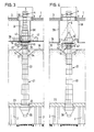
- 1 denotes a round silo, which stands as a high silo on legs 2 and as a large silo for the storage of granular bulk goods, e.g. Gypsum and the like.
- a loading device is provided for loading the silo 1 with the bulk material, and a discharge device is provided in the interior thereof for discharging the bulk material from the silo 1.
- the bulk material loading device has a storage conveyor 4 arranged stationary on the top or on the ceiling 3 of the silo 1, which advantageously consists of a storage belt and whose discharge end 5 lies above an opening 6 located in the middle of the ceiling 3.
- a storage conveyor 4 arranged stationary on the top or on the ceiling 3 of the silo 1, which advantageously consists of a storage belt and whose discharge end 5 lies above an opening 6 located in the middle of the ceiling 3.
- a stable bridge support 7 which extends across the silo and which can be raised and lowered vertically in the silo by means of a lifting mechanism, which here consists of several cable winches 8.
- the bridge support 7 is at its ends in Verti Kal guidance 9 rotatably guided, which are located on the silo wall 10 and extend substantially over the entire inner height of the silo.
- the vertical guides 9 consist of guide rails which are formed as ribs on the silo wall 10 or fastened to the silo wall.
- the bridge support 7 has a guide shoe 11 at its ends, which or the like with a guide groove 12. is provided for the engagement of the vertical guide 9. It is important that the bridge support 7 is supported on the silo wall 10 in a rotationally fixed manner via the vertical guides 9 and at the same time can be raised and lowered in the silo by means of the lifting mechanism 8.
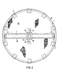
- a clearing device 14 is mounted via a rotary connection 13 with a vertical axis of rotation, which in the embodiments according to FIGS are pivotally mounted on a rotary member 17 which is connected to the bridge support 7 via the rotary connection 13.
- the rotary member 17 is rotatable about the vertical silo axis by means of a rotary drive 41 (only shown in FIGS. 5 and 6), the driven pinions 42 of which are in meshing engagement with a ring gear 43 on the rotary member 17, the two scraper arms 15 pivoting movements over the surface Execute 18 of the bulk goods in the silo.
- Each of the two scraper arms 15 is supported in the vicinity of the outer free end by a support arm 19 which is rigidly connected to the rotary member 17.
- the two scraper extractors 15 each have an endless scraper chain belt equipped with scratches, which is only indicated by dash-dotted lines at 20 in FIG. 1.
- the drive of the scraper chain belts 20 is reversible, so that the scraper chain belts can rotate in both directions of rotation.
- the discharge shaft In the middle of the silo there is a discharge shaft for the removal of the bulk material from the silo 1.
- the discharge shaft consists of a telescopic downpipe 21 arranged centrally in the silo, which tapers from the silo bottom 23 to the bridge girder 7.
- the largest pipe section 24 of the telescopic down pipe 22 passes through a central bottom opening 25, a funnel outlet 26 being arranged under its bulk material outlet opening.
- the lower end of the telescopic downpipe 22 can also lie above a discharge conveyor located under the silo bottom 23.
- the smallest diameter pipe section 27 of the telescopic down pipe 22 is connected to the rotary member 17 via a rotary coupling 28, which here consists of a pivot connection.
- a rotary coupling 28 which here consists of a pivot connection.
- the upper pipe section 27 has a bulk material entry opening which is formed by the open end of this pipe section and possibly a jacket opening on this pipe section.
- the telescopic down pipe 22 is designed such that it can follow the up and down movements of the bridge girder 7 and the clearing device 14, but does not take part in the pivoting movement of the clearing device 14 about the silo axis.
- a bulk material distribution device connected downstream of the above-mentioned storage conveyor 4 is attached to the bridge support 7.
- This consists of a distributor belt 30, which is arranged on the rotary member 17, according to FIGS. 1 to 3 at an angle of approximately 90 ° to the scraper extractor 15, as shown above all in FIG. 2.
- the distributor belt 30 can consist of a belt belt, a plate belt or another discharge belt.
- the rotary member 17 has an inner opening that receives the distributor band.
- a storage-storage telescopic tube 31 is arranged, which throws the bulk material fed approximately in the middle onto the distributor belt 30.
- the Ein alt telescopic tube 31 is fixed with its smallest diameter pipe section 32 in the region of the discharge end 5 of the storage conveyor 4, while it with its lower, larger diameter pipe sections 33 a central opening of the bridge beam 7, e.g. embodied as a slewing ring rotary joint 13 and the rotary member 17, with its lower discharge end lying above the distributor belt 30.
- the Ein electionss-telescopic tube 31 is also designed so that it can follow the lifting movements of the bridge beam 7 by extending and retracting.
- the bulk material fed in from above via the storage conveyor 4 and the telescopic tube 31 is thrown into the silo with the aid of the distributor belt 30, the rotary member 17 and thus the distributor belt executing a rotary movement around the silo axis, so that the bulk material becomes one ring-shaped accumulation is thrown into the silo.
- the scraper chains 20 of the scraper boom 15 are driven so that they over the bulk material convey the surface 18 of the bulk material radially outwards and distribute it evenly, so that a uniform filling of the silo is achieved with a flat surface 18 of the bulk material stack.
- the bridge girder 7 executes a slow upward movement together with the scraper arms 15, which is accomplished with the aid of the lifting mechanism 8. Since the cone-shaped bulk material accumulation in the silo is avoided by the bulk material distribution, the storage space of the silo can be used cheaply.
- the scraper chains 20 of the two scraper arms 14 are driven in the opposite direction so that they convey the bulk material over the surface 18 in the direction of the center of the silo.
- the space 34 caused by the formation of the embankment around the upper telescopic tube 27 is filled with bulk material.
- the bulk material fed from the scratch chains reaches the upper opening of the pipe section 27.
- the bulk material falls down through the telescopic downpipe 21 and can be drawn off below the silo bottom 23.
- the bridge support 7 executes a continuous downward movement with the clearing device 14, which movement ends when the clearing device reaches the silo floor.
- the telescopic tubes 21 and 31 can follow the up and down movements.
- the operating forces during bulk material loading and bulk material discharge are deposited on the silo wall 10 via the bridge girder 7 and the vertical guides 9.
- the telescopic downpipe 21 is not burdened by the operating forces and also does not serve as a rotary guide for the clearing device 14 which can be pivoted about the silo axis.
- the devices in the silo are easily accessible via the bridge support 7. It is advisable to provide a fixed platform 35 in the upper region of the silo, which, as in FIG.
- the embodiment according to FIG. 4 differs from that according to FIGS. 1 to 3 only in that the bulk material distribution device connected downstream of the storage conveyor 4 consists of a roof-shaped inclined deflector 37 which is fastened to the bridge support 7 and engages over it, so that the bulk material dropped into the silo 1 by the storage conveyor 4 is directed eccentrically to the bulk material pile via the deflector 37.
- the distributor belt 30 and the single-store telescopic tube 31 can be omitted here.
- the aforementioned stage 35 is connected to the silo wall 10 in the circumferential region and to the ceiling 3 in the interior region via tension members 38.
- the lifting speed of the bridge girder 7 must be matched to the conveying speed of the clearing device 14 during bulk material discharge. If, as in particular in the case of solidified bulk material, the scratching arms 15 are overloaded, they can pivot slightly upwards in their joints 16.
- the coupling of the support arms 19 with the scraper arms 15 is e.g. via bolt-slot connections or the like. so designed that these swiveling movements by small angles of e.g. 5 ° are possible.
- a predetermined swivel angle is reached, e.g. via an angle encoder or switch and the like. a signal is triggered, which either shuts down the entire device or reduces the lifting speed of the bridge girder.
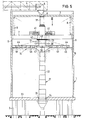
- FIGS. 5 and 6 differs from that according to FIGS. 1 to 3 essentially only in that instead of the clearing device 14 formed by the scraper arms 15, a clearing wheel 40 is provided which is rotatable about the vertical silo axis.
- the clearing wheel 40 is rotatably connected to the bridge support 7 via the rotary member 17 and the rotary connection 13, which ends in the vertical guides 9 on the silo wall 10.
- the rotary drive 41 of the cutting wheel 40 is located on the bridge carrier 7.
- the drive takes place via pinions 42 which are in engagement with a toothed ring 43 of the rotary member 17.
- the clearing wheel 40 consists of a spoke wheel, the hub of which is formed by the rotary member 17.
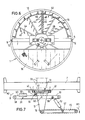
- ploughshare-like broaching members 45 are arranged at a radial distance from one another, which, as the top view in FIG. 6 shows, are exhibited at an acute angle to the radial direction and are radially offset from one another on the successive spokes 44 that during the rotation of the clearing wheel 40 in the direction of arrow 46, the bulk material is conveyed from the outside inwards in the direction of the telescopic down pipe 22.
- the bulk material is conveyed radially from the inside outward in the direction of the silo wall 10, so that the material thrown onto the bulk material pile from above Bulk material can be distributed over the cross-sectional area of the silo using the clearing wheel.
- the center of the clearing wheel there are 22 sickle-shaped guide vanes 47 above the telescopic down pipe, which promote the transfer of the bulk material conveyed inward by the clearing wheel 40 into the telescopic down pipe 21.
- the stage 35 can be designed here so that it only covers a segment of the circular silo, outside the lifting range of the bridge girder 7.
- one or more driven milling cutters for the clearing device assign that loosens the bulk material on the surface 18. 6 such a driven milling cutter is indicated at 48, which is located here on the spoke 44 of the clearing thread 40.
- FIG. 7 shows a partial view of a preferred embodiment of the clearing and distributor devices arranged on the rotary member 17.
- the discharge conveyor 30, which ejects the bulk material supplied via the storage telescopic tube 31 into the silo 1 and preferably consists of a distributor belt of the type mentioned, is mounted opposite to the scraper boom 15 on the rotary member 17 so that it at least partially compensates for the weight of the scraper boom 15 , Which is advantageous with regard to the load conditions on the rotary member 17, on the rotary connection 13, on the bridge girder 7 and on the guide rails 9.
- the discharge conveyor 30 is preferably pivotably mounted above the joint 16 of the scraper boom 15 in a pivot bearing 50, the horizontal joint axis of which runs parallel to the axis of the joint 16, in the manner of a two-armed lever.
- the section (lever arm) 51 of the discharge conveyor 30 pointing in the same direction as the scraper pointer 15 is coupled to the scraper boom 15 underneath via a pressure-resistant and tensile coupling member 52.
- the connecting joints of the coupling member 52 are designated 56 and 57.
- the section (lever arm) 53 lying on the other side of the pivot bearing 50 is supported with a stop 54 on a counter stop 55 of the rotary member 17.
- the arrangement here is such that the discharge conveyor 30 only partially compensates for the weight of the scraper boom 15.
- the load torque M1 of the scraper boom 15 is only partially compensated by the counter-torque M2 exerted by the discharge conveyor 30 in the withdrawal operation.
- the difference between the two moments M1 and M2 serves to hold down the scraper boom 15 on the storage material on the surface 18 of the bulk material pile.
- the ejection conveyor 30 is pivoted via the coupling member 52 so that its stop 54 stands out from the counter stop 55 of the rotary member 17.
- the relative movement of the two stops 54, 55, via which the differential torque M1 -M2 is supported in normal operation, can be converted into a e.g. convert electrical switching signal that interrupts the lowering movement of the bridge girder 7 by appropriate control of the lifting mechanism 8 or reduces its speed.
- the coupling member 52 can also be designed to be adjustable in length in order to be able to set the scraper arm 15 in a pivoting position that deviates from the horizontal.
- a pressure and tensile handlebar in the case of length adjustment a hydraulic cylinder, a servomotor with a threaded spindle or the like. be used.
- the bulk material to be stored is thrown into the silo at the free end 58 of the discharge conveyor 30, preferably in the vicinity of the silo wall, so that the bulk material can be distributed over the silo cross section by the scraper boom conveying towards the middle of the silo.
- the scraper boom need not be reversed in its working direction. It is advisable to arrange an additional counterweight 59 or a holder for such an additional counterweight on the discharge conveyor 30, as a result of which the above-mentioned differential torque M1 -M2 can be adjusted to suit the respective bulk material.
- the device 59 preferably consists of a weight box, which takes up a ballast weight.
- the bridge support 7 is designed such that it extends across the diameter of the silo and is guided at its two opposite ends by a guide shoe 11 on the vertical guides 9 of the silo wall.
- the bridge girder 7 can also consist of a cross or star-shaped support frame.
- the clearing devices 14 are clearly arranged so that they are arranged with their discharge end above the open end of the telescopic down pipe 21, where the bulk material is conveyed from above into the telescopic down pipe.
- the telescopic downpipe is included filled silo in the bulk goods heap.
- the insertion of the telescopic downpipe 21 is forced by the support weight of the bridge girder 7 and the devices connected to it. It may be advisable to provide the individual tubes 22 of the telescopic downpipe 21 on the outside with a surface coating which suppresses the adherence of the bulk material, preferably made of wear-resistant plastic material with good sliding properties, such as, in particular, Teflon or the like.
Landscapes
- Engineering & Computer Science (AREA)
- Mechanical Engineering (AREA)
- Filling Or Emptying Of Bunkers, Hoppers, And Tanks (AREA)
- Warehouses Or Storage Devices (AREA)
- Heterocyclic Carbon Compounds Containing A Hetero Ring Having Oxygen Or Sulfur (AREA)
Priority Applications (1)
| Application Number | Priority Date | Filing Date | Title |
|---|---|---|---|
| AT86104292T ATE39672T1 (de) | 1985-04-25 | 1986-03-27 | Einrichtung zur schuettgutfoerderung in silos. |
Applications Claiming Priority (2)
| Application Number | Priority Date | Filing Date | Title |
|---|---|---|---|
| DE19853514888 DE3514888A1 (de) | 1985-04-25 | 1985-04-25 | Einrichtung zur schuettgutfoerderung in silos |
| DE3514888 | 1985-04-25 |
Publications (2)
| Publication Number | Publication Date |
|---|---|
| EP0200000A1 true EP0200000A1 (fr) | 1986-11-05 |
| EP0200000B1 EP0200000B1 (fr) | 1989-01-04 |
Family
ID=6269052
Family Applications (1)
| Application Number | Title | Priority Date | Filing Date |
|---|---|---|---|
| EP86104292A Expired EP0200000B1 (fr) | 1985-04-25 | 1986-03-27 | Dispositif de manutention pour matières en vrac de silos |
Country Status (10)
| Country | Link |
|---|---|
| US (1) | US4721425A (fr) |
| EP (1) | EP0200000B1 (fr) |
| AT (1) | ATE39672T1 (fr) |
| AU (1) | AU580864B2 (fr) |
| DE (2) | DE3514888A1 (fr) |
| ES (1) | ES8704423A1 (fr) |
| FI (1) | FI861678A7 (fr) |
| IN (1) | IN165371B (fr) |
| NO (1) | NO861612L (fr) |
| ZA (1) | ZA863057B (fr) |
Cited By (8)
| Publication number | Priority date | Publication date | Assignee | Title |
|---|---|---|---|---|
| DE3644009A1 (de) * | 1986-12-22 | 1988-06-30 | Lentia Gmbh | N-substituierte, estergruppen enthaltende acrylamide |
| DE3743659A1 (de) * | 1987-12-22 | 1989-07-06 | Schade Foerdertechnik Gmbh & C | Ein- und ausspeichervorrichtung fuer silos |
| US4956491A (en) * | 1986-04-25 | 1990-09-11 | Nippon Paint Co., Ltd. | Alpha-alkylacrylamide derivatives and their polymers |
| DE4002378A1 (de) * | 1990-01-27 | 1991-08-08 | Moeller Hamburg Gmbh Co Kg | Behaelter mit kreisfoermigem querschnitt fuer schuettgueter |
| EP0445095A1 (fr) * | 1990-03-02 | 1991-09-04 | Uni Patent Ab | Appareil pour prévenir le classement de matières en vrac |
| WO1993016944A1 (fr) * | 1992-02-21 | 1993-09-02 | Ficote Oy | Dechargeur de masse pour un volume tel qu'un silo, comprenant un convoyeur articule monte en surplomb |
| FR2737480A1 (fr) * | 1995-08-04 | 1997-02-07 | Albert Suratteau | Dispositif pour desservir un silo en produit pulverulent |
| CN103183239A (zh) * | 2013-03-11 | 2013-07-03 | 河南威猛振动设备股份有限公司 | 一种旋转式给料机 |
Families Citing this family (28)
| Publication number | Priority date | Publication date | Assignee | Title |
|---|---|---|---|---|
| US4954036A (en) * | 1988-07-15 | 1990-09-04 | Walker Harold A | Variable height silo charge system |
| DE69001011T2 (de) * | 1989-06-02 | 1993-08-26 | Uni Patent Ab | Geraet zur verhinderung von trennung bei schuttmaterial. |
| WO1992003064A1 (fr) * | 1990-08-23 | 1992-03-05 | Liquid Carbonic Corporation | Procede de preparation de produits en lamelles frits contenant peu d'huile et produits obtenus |
| US5112180A (en) * | 1991-01-22 | 1992-05-12 | Hough International, Inc. | Silo top unloader |
| DE4307140C2 (de) * | 1993-03-06 | 1995-10-12 | Buddenberg Joerg Dr Ing | Silo für Schüttgüter mit heb- und senkbarem Querförderer |
| DE4409090C1 (de) * | 1994-03-17 | 1995-06-01 | Buddenberg Joerg Dr Ing | Silo für Schüttgüter |
| US5785483A (en) * | 1996-05-22 | 1998-07-28 | Jervis B. Webb Company | Bulk storage reclamation system and method |
| US5967729A (en) * | 1997-01-14 | 1999-10-19 | J-Star Industries, Inc. | Bottom discharge, rotating ring drive silo unloader |
| WO2000015525A1 (fr) * | 1998-09-10 | 2000-03-23 | Keith Van Gorp | Appareil pour produits en vrac |
| JP4249295B2 (ja) * | 1998-09-17 | 2009-04-02 | ソフタード工業株式会社 | 反応塔内触媒の抜出し装置およびその触媒の抜出し方法 |
| DE10206686B4 (de) * | 2002-02-18 | 2005-06-23 | SCHWäBISCHE HüTTENWERKE GMBH | Schüttgutlagerung mit Obenentnahme |
| WO2004023242A2 (fr) * | 2002-09-03 | 2004-03-18 | South, Phillip, Barry | Terminal de transfert avec tremie intermediaire |
| BR0312739B1 (pt) * | 2003-01-24 | 2012-10-16 | aparelho para armazenagem de aparas de madeira na forma de uma pilha de estocagem do tipo de topo curvo. | |
| US7127854B2 (en) * | 2003-02-13 | 2006-10-31 | Hedrick Thomas W | Bulk material storage facilities with access chases and/or internal filling structures |
| US20050191157A1 (en) * | 2004-02-27 | 2005-09-01 | Klaus-Sweerich Schroder | Storage for bulk goods with overhead withdrawal |
| US7438171B1 (en) | 2007-07-11 | 2008-10-21 | Benetech Inc. | Retractable and extendable material loader apparatus for directing material onto a conveyor |
| AU2012289366B2 (en) * | 2011-07-26 | 2016-05-19 | CCCC First Harbor Engineering Company Ltd. | Silo |
| US9109731B2 (en) * | 2012-11-26 | 2015-08-18 | General Electric Company | System and method for conveying solids through an outlet pipe |
| DE102014200452B4 (de) * | 2014-01-13 | 2025-03-27 | Hecht Technologie Gmbh | Entleerungseinrichtung |
| CN105858272B (zh) * | 2016-06-24 | 2019-04-09 | 安徽海螺集团有限责任公司 | 移动式卸料斗 |
| WO2018081901A1 (fr) * | 2016-11-03 | 2018-05-11 | Darrell Ford | Silo de stockage escamotable mobile |
| US10926966B2 (en) | 2017-05-23 | 2021-02-23 | Northwestern University | Devices for and methods of forming segregated layers from mixtures of granular materials |
| CN107324078A (zh) * | 2017-06-08 | 2017-11-07 | 上海电力环保设备总厂有限公司 | 大型封闭筒仓及其进料方法和出料方法 |
| US11273994B2 (en) | 2020-02-21 | 2022-03-15 | Benetech, Inc. | Bulk material precision in field belt conveyor loading apparatus |
| US12214309B2 (en) | 2021-04-06 | 2025-02-04 | Benetech, Inc. | Passive dust filter for an inspection hatch |
| US11919719B2 (en) | 2021-05-13 | 2024-03-05 | Benetech, Inc. | Drop and slide out idler assembly |
| DE102023105661B4 (de) * | 2023-02-20 | 2024-12-05 | Netzsch Pumpen & Systeme Gmbh | Entleerungssystem zum entleeren von pastösem material aus fassartigen behältern |
| CN117509176B (zh) * | 2023-12-19 | 2024-12-06 | 滨海县恒丰粮食机械有限公司 | 一种气力吸粮机的可调节出粮管 |
Citations (4)
| Publication number | Priority date | Publication date | Assignee | Title |
|---|---|---|---|---|
| DE831519C (de) * | 1950-03-16 | 1952-02-14 | Escher Wyss Maschinenfabrik G | Austragvorrichtung fuer Speicher, die zum Stapeln von kleinen Eisstuecken dienen |
| US3075657A (en) * | 1959-09-21 | 1963-01-29 | Rockwood & Co | Silage handling apparatus |
| CH430583A (de) * | 1965-10-22 | 1967-02-15 | Zemp Geb | Vorrichtung zur Entnahme von Heu aus einem zylindrischen Heuturm |
| GB1146938A (en) * | 1966-09-20 | 1969-03-26 | R Ateliers Belges Reunis S A A | Silo for bulk material |
Family Cites Families (15)
| Publication number | Priority date | Publication date | Assignee | Title |
|---|---|---|---|---|
| DE1250360B (fr) * | 1967-09-14 | |||
| US772911A (en) * | 1903-07-20 | 1904-10-25 | Heyl & Patterson | Coal-storage plant. |
| US2580306A (en) * | 1945-09-05 | 1951-12-25 | Leach Corp | Silo unloader |
| US2500043A (en) * | 1947-11-19 | 1950-03-07 | Int Harvester Co | Silo unloading device |
| US2649215A (en) * | 1950-06-26 | 1953-08-18 | William J Prendergast Jr | Silo charging and emptying machine |
| AT209954B (de) * | 1958-01-14 | 1960-07-11 | Philips Nv | Verfahren zum Herstellen von Halbleiterelektrodensystemen |
| DE1456866A1 (de) * | 1966-03-19 | 1969-12-11 | Schade Maschf Gustav | Vorrichtung zum Austragen von Schuettguetern |
| US3358856A (en) * | 1966-04-25 | 1967-12-19 | Ingeniors N Nils Weibull Ab Fa | Silo unloading device |
| DE1988164U (de) * | 1968-04-06 | 1968-06-20 | I A Lanvermeyer Fa | Vorrichtung zum ein- und ausbringen von gut in ein rundsilo. |
| DE1933337A1 (de) * | 1969-07-01 | 1971-01-21 | Kurt Schnellbacher | Verfahren zur Obenentnahme von Schuettguetern aus Zellen |
| US4022335A (en) * | 1974-04-25 | 1977-05-10 | Clayton & Lambert Manufacturing Co. | Spreading-unloading rotary sweep apparatus of the hole-forming sleeve type |
| DE3135439C2 (de) * | 1981-09-08 | 1984-02-16 | Engelbrecht + Lemmerbrock Gmbh + Co, 4520 Melle | Zylindrischer Hochsilo |
| DE3151841C2 (de) * | 1981-12-30 | 1984-05-17 | Engelbrecht + Lemmerbrock Gmbh + Co, 4520 Melle | Luftdicht abgeschlossener Hochsilo |
| NL8401399A (nl) * | 1984-05-02 | 1985-12-02 | Wit Cornelis Leendert De | Afvoerinrichting voor een silo. |
| DE3429023A1 (de) * | 1984-08-07 | 1986-02-20 | Jörg Wolfgang 4130 Moers Buddenberg | Silo mit kreisrundem grundriss fuer schuettgueter und einem an einer stuetzsaeule heb- und senkbar angeordneten querfoerderer |
-
1985
- 1985-04-25 DE DE19853514888 patent/DE3514888A1/de not_active Withdrawn
-
1986
- 1986-03-27 AT AT86104292T patent/ATE39672T1/de not_active IP Right Cessation
- 1986-03-27 DE DE8686104292T patent/DE3661618D1/de not_active Expired
- 1986-03-27 EP EP86104292A patent/EP0200000B1/fr not_active Expired
- 1986-04-10 IN IN280/CAL/86A patent/IN165371B/en unknown
- 1986-04-18 AU AU56364/86A patent/AU580864B2/en not_active Ceased
- 1986-04-21 US US06/854,439 patent/US4721425A/en not_active Expired - Lifetime
- 1986-04-22 FI FI861678A patent/FI861678A7/fi not_active Application Discontinuation
- 1986-04-24 ZA ZA863057A patent/ZA863057B/xx unknown
- 1986-04-24 NO NO861612A patent/NO861612L/no unknown
- 1986-04-24 ES ES554307A patent/ES8704423A1/es not_active Expired
Patent Citations (4)
| Publication number | Priority date | Publication date | Assignee | Title |
|---|---|---|---|---|
| DE831519C (de) * | 1950-03-16 | 1952-02-14 | Escher Wyss Maschinenfabrik G | Austragvorrichtung fuer Speicher, die zum Stapeln von kleinen Eisstuecken dienen |
| US3075657A (en) * | 1959-09-21 | 1963-01-29 | Rockwood & Co | Silage handling apparatus |
| CH430583A (de) * | 1965-10-22 | 1967-02-15 | Zemp Geb | Vorrichtung zur Entnahme von Heu aus einem zylindrischen Heuturm |
| GB1146938A (en) * | 1966-09-20 | 1969-03-26 | R Ateliers Belges Reunis S A A | Silo for bulk material |
Cited By (8)
| Publication number | Priority date | Publication date | Assignee | Title |
|---|---|---|---|---|
| US4956491A (en) * | 1986-04-25 | 1990-09-11 | Nippon Paint Co., Ltd. | Alpha-alkylacrylamide derivatives and their polymers |
| DE3644009A1 (de) * | 1986-12-22 | 1988-06-30 | Lentia Gmbh | N-substituierte, estergruppen enthaltende acrylamide |
| DE3743659A1 (de) * | 1987-12-22 | 1989-07-06 | Schade Foerdertechnik Gmbh & C | Ein- und ausspeichervorrichtung fuer silos |
| DE4002378A1 (de) * | 1990-01-27 | 1991-08-08 | Moeller Hamburg Gmbh Co Kg | Behaelter mit kreisfoermigem querschnitt fuer schuettgueter |
| EP0445095A1 (fr) * | 1990-03-02 | 1991-09-04 | Uni Patent Ab | Appareil pour prévenir le classement de matières en vrac |
| WO1993016944A1 (fr) * | 1992-02-21 | 1993-09-02 | Ficote Oy | Dechargeur de masse pour un volume tel qu'un silo, comprenant un convoyeur articule monte en surplomb |
| FR2737480A1 (fr) * | 1995-08-04 | 1997-02-07 | Albert Suratteau | Dispositif pour desservir un silo en produit pulverulent |
| CN103183239A (zh) * | 2013-03-11 | 2013-07-03 | 河南威猛振动设备股份有限公司 | 一种旋转式给料机 |
Also Published As
| Publication number | Publication date |
|---|---|
| AU580864B2 (en) | 1989-02-02 |
| IN165371B (fr) | 1989-10-07 |
| ES8704423A1 (es) | 1987-04-01 |
| FI861678A0 (fi) | 1986-04-22 |
| ZA863057B (en) | 1986-12-30 |
| EP0200000B1 (fr) | 1989-01-04 |
| ATE39672T1 (de) | 1989-01-15 |
| US4721425A (en) | 1988-01-26 |
| NO861612L (no) | 1986-10-27 |
| ES554307A0 (es) | 1987-04-01 |
| DE3661618D1 (en) | 1989-02-09 |
| DE3514888A1 (de) | 1986-11-06 |
| AU5636486A (en) | 1986-10-30 |
| FI861678A7 (fi) | 1986-10-26 |
Similar Documents
| Publication | Publication Date | Title |
|---|---|---|
| EP0200000B1 (fr) | Dispositif de manutention pour matières en vrac de silos | |
| DE60310614T2 (de) | Vorrichtung zum speichern und entladen von granulat | |
| EP0235612B1 (fr) | Dispositif pour décharger des silos | |
| DE3390175C2 (fr) | ||
| DE3233742C2 (de) | Silo für Schüttgut | |
| WO1986000281A1 (fr) | Silo de section circulaire pour matieres granuleuses | |
| DE1940714A1 (de) | Vorrichtung zum Austragen von Schuettguetern aus Silos | |
| DE3427410C1 (de) | Silo mit kreisrundem Grundriss fuer Schuettgueter und einem an einer Stuetzsaeule heb- und senkbar angeordneten Querfoerderer | |
| DE60319603T2 (de) | Vorrichtung zum Speichern und Entladen von Granulat | |
| EP0187788B1 (fr) | Silo pour matieres en vrac, avec un trace au sol circulaire, muni d'un transporteur transversal pouvant etre leve ou abaisse, monte sur une colonne de support | |
| DE3429023C2 (fr) | ||
| DE2541583C3 (de) | Vorrichtung zum Einebnen und Ausräumen von Schüttgut in bzw. aus Gutbehandlungsräumen, insbesondere für Mälzereien | |
| DE3626003A1 (de) | Silo fuer schuettgut | |
| EP0436068B1 (fr) | Méthode et dispositif pour le chargement, pauvre en poussière ou sans poussière, d'enceintes enfermées | |
| DE3743659A1 (de) | Ein- und ausspeichervorrichtung fuer silos | |
| AT383334B (de) | Vorrichtung fuer die zu- und abfuhr und die gleichmaessige verteilung von schuettgut, insbesondere flugasche, in einem tank | |
| DE2604829A1 (de) | Einspeichergeraet fuer das aufschuetten von rundhalden | |
| DE3134260C2 (de) | Vorrichtung zur Rückgewinnung von Schüttgut, insbesondere aus runden Schüttguthalden | |
| DE2442975C3 (de) | Anordnung zum Füllen und Entleeren eines turmartigen Lagerraumes | |
| EP0127648A1 (fr) | Convoyeuse a bande pour marchandises en vrac | |
| DE9212512U1 (de) | Einrichtung zum Ein- und Ausspeichern von Schüttgütern bei Kreislagern | |
| DE3514889A1 (de) | Einrichtung zum austragen von schuettgut aus einem silo | |
| DE8423415U1 (de) | Silo mit kreisrundem Grundriß für Schüttgüter und einem an einer Stützsäule heb- und senkbar angeordneten Querförderer | |
| DE6931662U (de) | Vorrichtung zum austragen von schuettguetern aus silos | |
| DE2926086A1 (de) | Anlage zum ein- und ausspeichern von schuettgut zu einer bzw. aus einer insbesondere in einer halle zumindest annaehernd kreiszylinderfoermiger wandung angeordneten halde |
Legal Events
| Date | Code | Title | Description |
|---|---|---|---|
| PUAI | Public reference made under article 153(3) epc to a published international application that has entered the european phase |
Free format text: ORIGINAL CODE: 0009012 |
|
| AK | Designated contracting states |
Kind code of ref document: A1 Designated state(s): AT BE CH DE FR GB IT LI LU NL SE |
|
| PUAB | Information related to the publication of an a document modified or deleted |
Free format text: ORIGINAL CODE: 0009199EPPU |
|
| PUAF | Information related to the publication of a search report (a3 document) modified or deleted |
Free format text: ORIGINAL CODE: 0009199SEPU |
|
| R17D | Deferred search report published (corrected) |
Effective date: 19861210 |
|
| RA1 | Application published (corrected) |
Date of ref document: 19861210 Kind code of ref document: A1 |
|
| 17P | Request for examination filed |
Effective date: 19870108 |
|
| RAP1 | Party data changed (applicant data changed or rights of an application transferred) |
Owner name: SCHADE FOERDERTECHNIK GMBH & CO. |
|
| 17Q | First examination report despatched |
Effective date: 19871106 |
|
| ITF | It: translation for a ep patent filed | ||
| GRAA | (expected) grant |
Free format text: ORIGINAL CODE: 0009210 |
|
| AK | Designated contracting states |
Kind code of ref document: B1 Designated state(s): AT BE CH DE FR GB IT LI LU NL SE |
|
| REF | Corresponds to: |
Ref document number: 39672 Country of ref document: AT Date of ref document: 19890115 Kind code of ref document: T |
|
| PGFP | Annual fee paid to national office [announced via postgrant information from national office to epo] |
Ref country code: LU Payment date: 19890118 Year of fee payment: 4 |
|
| PGFP | Annual fee paid to national office [announced via postgrant information from national office to epo] |
Ref country code: CH Payment date: 19890130 Year of fee payment: 4 |
|
| GBT | Gb: translation of ep patent filed (gb section 77(6)(a)/1977) | ||
| REF | Corresponds to: |
Ref document number: 3661618 Country of ref document: DE Date of ref document: 19890209 |
|
| ET | Fr: translation filed | ||
| PGFP | Annual fee paid to national office [announced via postgrant information from national office to epo] |
Ref country code: AT Payment date: 19890309 Year of fee payment: 4 |
|
| PGFP | Annual fee paid to national office [announced via postgrant information from national office to epo] |
Ref country code: SE Payment date: 19890323 Year of fee payment: 4 |
|
| PG25 | Lapsed in a contracting state [announced via postgrant information from national office to epo] |
Ref country code: LU Free format text: LAPSE BECAUSE OF NON-PAYMENT OF DUE FEES Effective date: 19890331 |
|
| PLBE | No opposition filed within time limit |
Free format text: ORIGINAL CODE: 0009261 |
|
| STAA | Information on the status of an ep patent application or granted ep patent |
Free format text: STATUS: NO OPPOSITION FILED WITHIN TIME LIMIT |
|
| 26N | No opposition filed | ||
| PG25 | Lapsed in a contracting state [announced via postgrant information from national office to epo] |
Ref country code: AT Effective date: 19900327 |
|
| PG25 | Lapsed in a contracting state [announced via postgrant information from national office to epo] |
Ref country code: SE Effective date: 19900328 |
|
| PG25 | Lapsed in a contracting state [announced via postgrant information from national office to epo] |
Ref country code: LI Effective date: 19900331 Ref country code: CH Effective date: 19900331 |
|
| REG | Reference to a national code |
Ref country code: CH Ref legal event code: PL |
|
| PGFP | Annual fee paid to national office [announced via postgrant information from national office to epo] |
Ref country code: FR Payment date: 19921230 Year of fee payment: 8 |
|
| PGFP | Annual fee paid to national office [announced via postgrant information from national office to epo] |
Ref country code: BE Payment date: 19930310 Year of fee payment: 8 |
|
| ITTA | It: last paid annual fee | ||
| PGFP | Annual fee paid to national office [announced via postgrant information from national office to epo] |
Ref country code: NL Payment date: 19930331 Year of fee payment: 8 |
|
| PG25 | Lapsed in a contracting state [announced via postgrant information from national office to epo] |
Ref country code: BE Effective date: 19940331 |
|
| BERE | Be: lapsed |
Owner name: SCHADE FORDERTECHNIK G.M.B.H. & CO. Effective date: 19940331 |
|
| PG25 | Lapsed in a contracting state [announced via postgrant information from national office to epo] |
Ref country code: NL Effective date: 19941001 |
|
| NLV4 | Nl: lapsed or anulled due to non-payment of the annual fee | ||
| PG25 | Lapsed in a contracting state [announced via postgrant information from national office to epo] |
Ref country code: FR Effective date: 19941130 |
|
| REG | Reference to a national code |
Ref country code: FR Ref legal event code: ST |
|
| EUG | Se: european patent has lapsed |
Ref document number: 86104292.7 Effective date: 19910110 |
|
| PGFP | Annual fee paid to national office [announced via postgrant information from national office to epo] |
Ref country code: GB Payment date: 19950317 Year of fee payment: 10 |
|
| PG25 | Lapsed in a contracting state [announced via postgrant information from national office to epo] |
Ref country code: GB Effective date: 19960327 |
|
| GBPC | Gb: european patent ceased through non-payment of renewal fee |
Effective date: 19960327 |
|
| PGFP | Annual fee paid to national office [announced via postgrant information from national office to epo] |
Ref country code: DE Payment date: 19991227 Year of fee payment: 15 |
|
| PG25 | Lapsed in a contracting state [announced via postgrant information from national office to epo] |
Ref country code: DE Free format text: LAPSE BECAUSE OF NON-PAYMENT OF DUE FEES Effective date: 20020101 |
|
| PG25 | Lapsed in a contracting state [announced via postgrant information from national office to epo] |
Ref country code: IT Free format text: LAPSE BECAUSE OF NON-PAYMENT OF DUE FEES;WARNING: LAPSES OF ITALIAN PATENTS WITH EFFECTIVE DATE BEFORE 2007 MAY HAVE OCCURRED AT ANY TIME BEFORE 2007. THE CORRECT EFFECTIVE DATE MAY BE DIFFERENT FROM THE ONE RECORDED. Effective date: 20050327 |