EP0200140B1 - Dispositif pour boucher des orifices traversés par des conduites, câbles ou objets similaires - Google Patents
Dispositif pour boucher des orifices traversés par des conduites, câbles ou objets similaires Download PDFInfo
- Publication number
- EP0200140B1 EP0200140B1 EP86105526A EP86105526A EP0200140B1 EP 0200140 B1 EP0200140 B1 EP 0200140B1 EP 86105526 A EP86105526 A EP 86105526A EP 86105526 A EP86105526 A EP 86105526A EP 0200140 B1 EP0200140 B1 EP 0200140B1
- Authority
- EP
- European Patent Office
- Prior art keywords
- clamping element
- pipe
- means according
- sleeves
- pipe section
- Prior art date
- Legal status (The legal status is an assumption and is not a legal conclusion. Google has not performed a legal analysis and makes no representation as to the accuracy of the status listed.)
- Expired
Links
- 238000007789 sealing Methods 0.000 title claims description 19
- 230000004323 axial length Effects 0.000 claims description 8
- 230000000295 complement effect Effects 0.000 claims description 4
- 239000013013 elastic material Substances 0.000 claims description 2
- 238000012856 packing Methods 0.000 claims 2
- 238000000926 separation method Methods 0.000 claims 1
- 239000004033 plastic Substances 0.000 description 7
- 238000004519 manufacturing process Methods 0.000 description 3
- 230000000694 effects Effects 0.000 description 2
- 239000000463 material Substances 0.000 description 2
- 238000012986 modification Methods 0.000 description 2
- 230000004048 modification Effects 0.000 description 2
- 230000002411 adverse Effects 0.000 description 1
- 238000010276 construction Methods 0.000 description 1
- 230000007797 corrosion Effects 0.000 description 1
- 238000005260 corrosion Methods 0.000 description 1
- 230000006866 deterioration Effects 0.000 description 1
- 230000002542 deteriorative effect Effects 0.000 description 1
- 238000003780 insertion Methods 0.000 description 1
- 230000037431 insertion Effects 0.000 description 1
- 239000000314 lubricant Substances 0.000 description 1
- 239000002184 metal Substances 0.000 description 1
- 230000000149 penetrating effect Effects 0.000 description 1
Images
Classifications
-
- H—ELECTRICITY
- H02—GENERATION; CONVERSION OR DISTRIBUTION OF ELECTRIC POWER
- H02G—INSTALLATION OF ELECTRIC CABLES OR LINES, OR OF COMBINED OPTICAL AND ELECTRIC CABLES OR LINES
- H02G3/00—Installations of electric cables or lines or protective tubing therefor in or on buildings, equivalent structures or vehicles
- H02G3/22—Installations of cables or lines through walls, floors or ceilings, e.g. into buildings
-
- F—MECHANICAL ENGINEERING; LIGHTING; HEATING; WEAPONS; BLASTING
- F16—ENGINEERING ELEMENTS AND UNITS; GENERAL MEASURES FOR PRODUCING AND MAINTAINING EFFECTIVE FUNCTIONING OF MACHINES OR INSTALLATIONS; THERMAL INSULATION IN GENERAL
- F16L—PIPES; JOINTS OR FITTINGS FOR PIPES; SUPPORTS FOR PIPES, CABLES OR PROTECTIVE TUBING; MEANS FOR THERMAL INSULATION IN GENERAL
- F16L5/00—Devices for use where pipes, cables or protective tubing pass through walls or partitions
- F16L5/02—Sealing
- F16L5/06—Sealing by means of a swivel nut compressing a ring or sleeve
-
- H—ELECTRICITY
- H01—ELECTRIC ELEMENTS
- H01B—CABLES; CONDUCTORS; INSULATORS; SELECTION OF MATERIALS FOR THEIR CONDUCTIVE, INSULATING OR DIELECTRIC PROPERTIES
- H01B17/00—Insulators or insulating bodies characterised by their form
- H01B17/26—Lead-in insulators; Lead-through insulators
- H01B17/30—Sealing
- H01B17/303—Sealing of leads to lead-through insulators
- H01B17/308—Sealing of leads to lead-through insulators by compressing packing material
Definitions
- the invention relates to a device for sealing pipes, cables or the like. penetrated openings in walls, masonry or the like, with two axially spaced, relatively movable disc-shaped and at least one axially extending bore having clamping elements, between which a seal made of elastic material is arranged and in sealing contact on the outer circumference of the pipeline (s) and is pressable on the inner circumference of the opening, the seal consisting of two coaxially arranged, radially spaced elastic sleeves, of which the radially inner sleeve one or the like of the outer circumference of the pipeline. adapted inner diameter and the radially outer sleeve has an outer diameter which corresponds to the inner circumference of the opening.
- a very simple sealing device of the type mentioned initially consists of two annular plates which are arranged on the two axial end faces of a comparatively thick annular rubber washer.
- the outside diameter of the plates is slightly smaller than the outside diameter of the rubber washer. Both the two plates and the rubber washer are penetrated by an aligned hole through which a pipe or the like. is passed through.
- One of the two plates of the known device is provided with, for example, three stud bolts which are passed through corresponding holes in the rubber washer and through corresponding holes in the other plate and have threads at their free ends. With the nuts screwed onto this thread, the clear distance between the two plates can be reduced. This reduces the thickness of the rubber washer and the displaced rubber is pressed radially outwards and inwards. It lies on the inside of the outer circumference of the pipe penetrating the axial bore and on the outside of the inner circumference of the opening. The seal that can be achieved in this way is generally satisfactory. There is occasionally a certain problem if the exposed wall surface within the opening has a high level of roughness or irregularity, as occurs with openings through concrete walls. In these cases in particular, a casing pipe was previously installed in the opening, which in turn formed a well-suited abutment for the sealing device with its comparatively clean inner surface.
- a sealing device partially made of plastic is known from DE-B 1 196 447.
- the seal used in this prior art consists of two coaxially arranged, radially spaced elastic sleeves, of which the radially inner sleeve or the like on the outer circumference of the pipeline. adapted inner diameter and the radially outer sleeve has an outer diameter which corresponds to the inner circumference of the opening.
- the carrier sleeve is provided with a thread on the outside and inside, onto which pressure pieces can be screwed. By turning the pressure pieces relative to the carrier sleeve, the elastic sleeves are axially compressed and thereby exert the desired sealing forces in the radial direction. The clamping forces are no longer introduced in a punctiform manner.
- the known sealing device requires two external and two internal threaded sections, and in addition to the sealing sleeves, it has at least three interacting and assembled parts, whereby the production and assembly costs are adversely affected.
- the invention was based on the object of developing a device of the type mentioned at the outset in such a way that it can be produced from a few plastic parts without the risk of a deteriorating sealing effect.
- the sealing device consists only of there are still two interconnected parts which, when screwed together, effect both the sealing to the outside and the sealing to the inside. Plastic deformations of the clamping elements are no longer to be feared even when they are made of plastic.
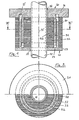
- the first embodiment according to FIGS. 1 and 2 relates to a device which is pushed onto a pipeline 10 during assembly and pressed into the opening (not shown).
- the individual elements of the device need not be divided in this type of assembly.
- the device has two clamping elements 20, 30, each of which consists of an annular plate 21 or 31 with a tube section 22 or 32 starting from this plate.
- Fig. 1 shows that the edge 23 of the plate 21 has a smaller diameter than the corresponding edge of the other plate 31.
- the resulting radial projection of the other plate 31 forms a contact surface up to which the device is inserted into the opening, not shown.
- the plate 21 is provided with a central bore 24 for the passage of the pipeline 10.
- the other plate 31 has a corresponding central bore 34.
- the pipe section 22 of the clamping element 20 runs coaxially to the axis 15 of the device and is an integral part of the clamping element. As evidenced by the drawing, he has both. a distance from the edge 23 and from the central bore 24 and is provided with an internal thread.
- the pipe section 32 of the clamping element 30 corresponds to the pipe section 22 already described. However, both its outer and its inner diameter is smaller than the corresponding diameter of the pipe section 22. On its outer circumference, the pipe section 32 belonging to the clamping element 30 is provided with an external thread that corresponds to the internal thread of the other pipe section 22. Accordingly, both pipe sections can be screwed together. The consequence of this is an axial change in the distance between the two plates 21, 31.
- the device is equipped with a two-part seal.
- This seal is from two coaxially arranged sleeves 40, 42, hoses or the like. formed, which are usually made of rubber.
- the radially outer surface of the two sleeves 40 lies with its radially inner surface on the outer circumference of the tube section 22 and extends in the axial direction between the outer edge region of the plate 21 and a corresponding section of the other plate 31.
- the outer diameter of the sleeve 40 is the same or slightly larger than the diameter of the edge 23 of the plate 21.
- the radially inner sleeve 42 is supported in the radial direction on the one hand on the pipe 10 and on the other hand on the inner surface of the pipe section 32 of the clamping element 30. It is enclosed in the axial direction between the inner sections of the plates 21, 31st
- both the plates 21, 31 and the inner sleeve 42 can have a plurality of parallel bores analogous to the bores 24, 34, as is known as such in the prior art, so that with one device also several pipes, cables or the like can be sealed together.
- the device in the breakthrough is pushed over the pipe 10 protruding from the breakthrough.
- the two clamping elements 20, 30 are rotated against each other to such an extent that the outer sleeve 40 bulges slightly outwards. This is intended to ensure that the outer sleeve 40 already bears against the wall of the opening or casing pipe with a slight pretension when the device is inserted into the opening.
- the plate 31 remaining outside the opening is rotated by hand or by means of a tool, so that its pipe section 32 is screwed further into the other pipe section 22.
- the aforementioned pretension between the outer sleeve 40 and the opening means that the clamping element 20 located within the opening does not rotate. A seal can thus be achieved from one side of the opening, so that the device can also be used where the structural conditions only allow access to the opening from one side.
- Fig. 1 shows the example of the plate 31 of the clamping element 30 that one can achieve a sufficient degree of axial mobility of the two clamping elements to each other and at the same time a complete support of the sleeve 40 in the clamped (not shown) state in that in the axial extension of the pipe section 22nd an annular groove 35 is provided in the plate 31, into which the tube section 22 can move when the device is tightened.
- a corresponding annular groove can also be provided in the other plate 21 if necessary.
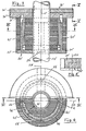
- the annular plate of the tensioning element 30 ' consists of two approximately semicircular segments 31', 31 ", which are provided with folds complementary to one another along a center line 50, as shown in particular in FIG. 5.
- the tube section 32 ' of the tensioning element 30 ' is correspondingly divided into two half-shells, which are also provided with complementary folds in the area of the joints, as indicated in Fig. 4 at 52.
- the tensioning element 30' is therefore in two parts and can therefore be fitted around a pipeline that has already been laid Assemble 10 '.
- the tensioning element 20 ' is also formed in two parts.
- the complementary folds of the segments 21 ', 21 "of the associated plate can be seen at 54 and the folds of the associated tube section 22' can be seen at 56 (FIGS. 3 and 4).
- the drawing shows that the position of the folds of the Clamping element 30 '(line 50) is rotated by approximately 90 ° with respect to the position of the folds of the clamping element 20' (line 58).
- the sleeves 40 'or 42' of this second embodiment are - as mentioned - either supplied as flat blanks which are glued together on their end faces 44 'or 46' immediately from the assembly, or cut open on these lines in order to the piping is put around and then glued again.
- the outer sleeve 40 ' is pushed over the segments 21', 21 of the tensioning element 20 'which are adjacent to one another and holds the parts thereof together.
- the inner sleeve 42 ' is pushed into the interior of the clamping element 20', whereupon the two segments 31 ', 31 "held together by hand can be screwed into the clamping element 20' with the corresponding shells of their tube section. It is understood that when screwing in, the position of line 58 changes to the position of line 50 according to the rotational movement.
- the device of the second embodiment corresponds to that of the first embodiment.
Landscapes
- Engineering & Computer Science (AREA)
- General Engineering & Computer Science (AREA)
- Architecture (AREA)
- Civil Engineering (AREA)
- Structural Engineering (AREA)
- Mechanical Engineering (AREA)
- Laying Of Electric Cables Or Lines Outside (AREA)
Claims (8)
Applications Claiming Priority (2)
| Application Number | Priority Date | Filing Date | Title |
|---|---|---|---|
| DE8512815U DE8512815U1 (de) | 1985-05-02 | 1985-05-02 | Vorrichtung zum Abdichten von von Rohrleitungen, Kabel od. dgl. durchsetzten Durchbrüchen |
| DE8512815U | 1985-05-02 |
Publications (3)
| Publication Number | Publication Date |
|---|---|
| EP0200140A2 EP0200140A2 (fr) | 1986-11-05 |
| EP0200140A3 EP0200140A3 (en) | 1987-05-06 |
| EP0200140B1 true EP0200140B1 (fr) | 1989-04-05 |
Family
ID=6780546
Family Applications (1)
| Application Number | Title | Priority Date | Filing Date |
|---|---|---|---|
| EP86105526A Expired EP0200140B1 (fr) | 1985-05-02 | 1986-04-22 | Dispositif pour boucher des orifices traversés par des conduites, câbles ou objets similaires |
Country Status (2)
| Country | Link |
|---|---|
| EP (1) | EP0200140B1 (fr) |
| DE (2) | DE8512815U1 (fr) |
Families Citing this family (1)
| Publication number | Priority date | Publication date | Assignee | Title |
|---|---|---|---|---|
| CN104466839B (zh) * | 2014-11-28 | 2018-02-23 | 国家电网公司 | 电缆穿墙保护装置 |
Family Cites Families (3)
| Publication number | Priority date | Publication date | Assignee | Title |
|---|---|---|---|---|
| DE1196447B (de) * | 1962-02-27 | 1965-07-08 | Gustav F J Schroeder | Dichtungsanordnung fuer Wanddurchfuehrungen an Rohrleitungen oder Kabeln |
| DE1204472B (de) * | 1962-10-09 | 1965-11-04 | Rheinisches Metallwerk Gmbh | Mauerdurchfuehrung fuer Installationsrohre mit einem radial verspannbaren Pressring |
| DE3102710A1 (de) * | 1981-01-28 | 1982-08-12 | Erik Groesen 8800 Aarhus Jensen | Dichtungsvorrichtung |
-
1985
- 1985-05-02 DE DE8512815U patent/DE8512815U1/de not_active Expired
-
1986
- 1986-04-22 EP EP86105526A patent/EP0200140B1/fr not_active Expired
- 1986-04-22 DE DE8686105526T patent/DE3662721D1/de not_active Expired
Also Published As
| Publication number | Publication date |
|---|---|
| DE8512815U1 (de) | 1985-06-13 |
| DE3662721D1 (en) | 1989-05-11 |
| EP0200140A3 (en) | 1987-05-06 |
| EP0200140A2 (fr) | 1986-11-05 |
Similar Documents
| Publication | Publication Date | Title |
|---|---|---|
| DE3216938C2 (de) | Rohrverbindung | |
| DE3631812C2 (de) | Rohr- oder Schlauchverbindungselement | |
| EP0663047B1 (fr) | Systeme tubulaire pour constructions tubulaires | |
| EP0039447A1 (fr) | Accessoire de câble fileté | |
| DE2948286A1 (de) | Ganzmetallene verbindung | |
| DE2621044B2 (de) | Rohrverbindung | |
| DE2610878A1 (de) | Rohrverbindung mit einer schraubmuffe | |
| EP0100771B1 (fr) | Cuvelages pour le soutènement des tunnels et des puits | |
| EP0200140B1 (fr) | Dispositif pour boucher des orifices traversés par des conduites, câbles ou objets similaires | |
| DE3102710C2 (fr) | ||
| EP0905426A2 (fr) | Dispositif d'étanchéité pour un passage de conduite à travers une ouverture murale | |
| EP0566973B1 (fr) | Traversée pour tuyaux ou similaires | |
| DE1958205A1 (de) | Schubsicherung bei Muffenverbindungen von Rohren | |
| WO2002098628A2 (fr) | Bague de serrage pour le raccordement axial de pieces cylindriques | |
| EP0073050A1 (fr) | Accouplement de serrage pour corps lisses et ronds, notamment tuyaux et barres | |
| DE102014114959B4 (de) | Rohrverbindungsvorrichtung | |
| DE4009403C2 (de) | Rohrleitungskupplung | |
| EP0180656B1 (fr) | Raccords pour joindre des tubes en matières fragiles | |
| EP0043593A1 (fr) | Dispositif pour raccorder deux brides | |
| DE29901351U1 (de) | Verstellbarer Keilring | |
| DE3536784C2 (fr) | ||
| DE9112027U1 (de) | Dünnwandiges Rohr, insbesondere Hüllrohr für Zugglieder für Anker im Boden | |
| DE3911258A1 (de) | Abdichtende schraubverbindungsvorrichtung fuer ein glasrohr oder dergleichen mit einem anschlussrohr oder -schlauch bei laboreinrichtungen oder dergleichen | |
| DE3707432C2 (fr) | ||
| DE2711360A1 (de) | Schubsicherung fuer rohrverbindungen |
Legal Events
| Date | Code | Title | Description |
|---|---|---|---|
| PUAI | Public reference made under article 153(3) epc to a published international application that has entered the european phase |
Free format text: ORIGINAL CODE: 0009012 |
|
| AK | Designated contracting states |
Kind code of ref document: A2 Designated state(s): CH DE LI NL |
|
| PUAB | Information related to the publication of an a document modified or deleted |
Free format text: ORIGINAL CODE: 0009199EPPU |
|
| RA1 | Application published (corrected) |
Date of ref document: 19861210 Kind code of ref document: A2 |
|
| PUAL | Search report despatched |
Free format text: ORIGINAL CODE: 0009013 |
|
| AK | Designated contracting states |
Kind code of ref document: A3 Designated state(s): CH DE LI NL |
|
| 17P | Request for examination filed |
Effective date: 19870812 |
|
| 17Q | First examination report despatched |
Effective date: 19871210 |
|
| GRAA | (expected) grant |
Free format text: ORIGINAL CODE: 0009210 |
|
| AK | Designated contracting states |
Kind code of ref document: B1 Designated state(s): CH DE LI NL |
|
| REF | Corresponds to: |
Ref document number: 3662721 Country of ref document: DE Date of ref document: 19890511 |
|
| PLBE | No opposition filed within time limit |
Free format text: ORIGINAL CODE: 0009261 |
|
| STAA | Information on the status of an ep patent application or granted ep patent |
Free format text: STATUS: NO OPPOSITION FILED WITHIN TIME LIMIT |
|
| 26N | No opposition filed | ||
| PGFP | Annual fee paid to national office [announced via postgrant information from national office to epo] |
Ref country code: NL Payment date: 19920430 Year of fee payment: 7 Ref country code: DE Payment date: 19920430 Year of fee payment: 7 |
|
| PGFP | Annual fee paid to national office [announced via postgrant information from national office to epo] |
Ref country code: CH Payment date: 19920518 Year of fee payment: 7 |
|
| PG25 | Lapsed in a contracting state [announced via postgrant information from national office to epo] |
Ref country code: LI Effective date: 19930430 Ref country code: CH Effective date: 19930430 |
|
| PG25 | Lapsed in a contracting state [announced via postgrant information from national office to epo] |
Ref country code: NL Effective date: 19931101 |
|
| NLV4 | Nl: lapsed or anulled due to non-payment of the annual fee | ||
| REG | Reference to a national code |
Ref country code: CH Ref legal event code: PL |
|
| PG25 | Lapsed in a contracting state [announced via postgrant information from national office to epo] |
Ref country code: DE Effective date: 19940101 |