EP0200236B1 - Machine et méthode pour former les bobines sur les stators des moteurs électriques - Google Patents
Machine et méthode pour former les bobines sur les stators des moteurs électriques Download PDFInfo
- Publication number
- EP0200236B1 EP0200236B1 EP86200364A EP86200364A EP0200236B1 EP 0200236 B1 EP0200236 B1 EP 0200236B1 EP 86200364 A EP86200364 A EP 86200364A EP 86200364 A EP86200364 A EP 86200364A EP 0200236 B1 EP0200236 B1 EP 0200236B1
- Authority
- EP
- European Patent Office
- Prior art keywords
- needle
- stator
- winding
- axis
- pole piece
- Prior art date
- Legal status (The legal status is an assumption and is not a legal conclusion. Google has not performed a legal analysis and makes no representation as to the accuracy of the status listed.)
- Expired - Lifetime
Links
Images
Classifications
-
- H—ELECTRICITY
- H02—GENERATION; CONVERSION OR DISTRIBUTION OF ELECTRIC POWER
- H02K—DYNAMO-ELECTRIC MACHINES
- H02K15/00—Processes or apparatus specially adapted for manufacturing, assembling, maintaining or repairing of dynamo-electric machines
- H02K15/08—Forming windings by laying conductors into or around core parts
- H02K15/095—Forming windings by laying conductors into or around core parts by laying conductors around salient poles
-
- Y—GENERAL TAGGING OF NEW TECHNOLOGICAL DEVELOPMENTS; GENERAL TAGGING OF CROSS-SECTIONAL TECHNOLOGIES SPANNING OVER SEVERAL SECTIONS OF THE IPC; TECHNICAL SUBJECTS COVERED BY FORMER USPC CROSS-REFERENCE ART COLLECTIONS [XRACs] AND DIGESTS
- Y10—TECHNICAL SUBJECTS COVERED BY FORMER USPC
- Y10T—TECHNICAL SUBJECTS COVERED BY FORMER US CLASSIFICATION
- Y10T29/00—Metal working
- Y10T29/49—Method of mechanical manufacture
- Y10T29/49002—Electrical device making
- Y10T29/49009—Dynamoelectric machine
Definitions
- the invention relates to a machine and a method for forming windings on electric motor stators.
- Machines for forming stator windings are known in which a needle, driven with rectilinear reciprocating motion combined with reciprocating rotary motion about its axis, carries at least one copper wire unwinding from a reel in order to deposit it in the stator armature slot.
- the needle comprises one point if a single winding is to be made, or comprises two opposing points if both windings are to be made simultaneously, as shown in document FR-A-2514211.
- the needle always has its axis of advancement and rotation coinciding with the stator axis in order to enable it to slide in the open spaces between the slots within the stator during its to-and-fro movement and to lie equidistant from all the armature slots on which its points are to wind the copper wire.
- winding forms also known as shoes, are applied to the ends of the respective slots, and are shaped in such a manner as to accompany the copper wire of the needle into the slot, when the needle rotates external to the stator.
- tensioning devices have to be set up to hold the shoes rigidly against the stator during the forming stage, and to enable them to be rapidly released from it when the forming is complete.
- the main object of the invention is to provide a machine for forming a stator winding which enables the use of winding forms or shoes to be dispensed with, together with their tensioning devices and the devices which release them from the stator.
- a further object of the invention is to improve the winding which is formed about each slot by reducing the needle stroke and the loop which the wire makes external to the stator, by virtue of the elimination of the shoes, as determined by the main object of the invention.
- stator winding machine as claimed in claim 1 and by a method for forming a winding in electric motor stators as claimed in claim 7.
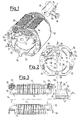
- the drawings illustrate a two-winding stator of traditional type, comprising the hollow cylinder 10 constituted by high magnetic permeability laminations which, on the inside of the structure, assume two opposing dovetail configurations 11 which define the slots 12 in which the windings 13 are disposed.
- plastics sections 14 which reproduce its surface, to project at 15 from the dovetails 11 where they comprises a tooth 16 intended to form a frontal retainer for the winding 13 (non always essential).
- the needle 17 is of the single point type 18 and, according to the invention, has its translation and rotation axis x eccentric to the stator centre y.
- the axis x is at a distance a from the centre y, along the fictitious straight line z passing through the middle of the two opposing dovetails 11, such that the distance b between the axis x and the end 19 of the point 18 is greater than the distance c between the axis x and the end of that tooth 16 which is closest to said axis x.
- the needle 17 makes the winding 13 without requiring the aid of the currently necessary shoes. This is because when the needle is external to the stator and has to make the wire undergo the loop about the supports 13, the point 18 is in a position almost in contact with the tooth 16 ( Figure 3), and its end 19 is advantageously beyond the upper end of said tooth so that the wire which projects from the point 18 does not require any accompaniment in order to become lodged in the recess formed between the walls of the section 14 and the tooth 16.
- the wire delivered by the needle makes a smaller loop as it is practically in contact with the support 15 during the rotation of the point 18, and thus the winding is certainly improved in terms of its compactness.
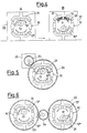
- a first method can consist of providing a second working station downstream of the first, in which a second needle is mounted eccentric to the stator as in the first station, but with respect to the other slot on which the new winding 13 is to be formed.
- Figure 4 diagrammatically illustrates how this first method can be attained, the stator 10 being retained in position by jaws 21 of a frame 22 in the station A in which a needle 17 is eccentric to the upper slot 12'.
- the frame 22 is moved into the station B in which the needle 17 is eccentric to the lower slot 12", on which the second winding can be formed.
- Another method can consist of providing a device which causes the stator to rotate through 180° about its centre y so that, while keeping the position of the needle 17 unchanged, the second slot now becomes located in the position previously occupied by the first with respect to the needle.
- Figure 5 diagrammatically illustrates a possible embodiment of this second method in which the support frame for the stator 10 is in the form of a ring gear 23 which engages with a gear wheel 24 rotated by a motor 25 so as to cause the stator to rotate through 180° after the formation of the winding on the slot 12' and position the slot 12" to correspond with said needle 17 for the subsequent formation.
- a third method is to provide two side-by-side stations operating on two stators, these latter being interconnected by a device which causes them to rotate simultaneously through 180°, so that they each become rotated through 180° about their own needle to enable the winding to now be made on the empty slots.
- This third method would mean that there would be no change in the present operating times of machines comprising needles with two opposing points for forming windings simultaneously on both the slots, in that the complete formation takes place on two stators simultaneously.
- This third method is diagrammatically illustrated in Figure 6 in which it can be seen that the supports 23 for the two side-by-side stators 10 are toothed as in the method of Figure 5, and engage with a gear wheel 24 of the type shown in Figure 5 but interposed between the two supports 23.
Landscapes
- Engineering & Computer Science (AREA)
- Manufacturing & Machinery (AREA)
- Power Engineering (AREA)
- Manufacture Of Motors, Generators (AREA)
- Windings For Motors And Generators (AREA)
Claims (15)
- Machine pour bobinages statoriques qui comprend une aiguille (17) ayant un axe longitudinal (x) et une pointe (18) se projetant transversalement audit axe longitudinal, un moyen pour entraîner cette aiguille (17) et un moyen pour fournir un fil (13) à la pointe (18) de cette aiguille, le moyen pour entraîner l'aiguille comprenant un moyen de déplacement de cette aiguille (17) d'un mouvement linéaire alternatif le long dudit axe longitudinal (x) et d'un mouvement de rotation alternatif autour dudit axe longitudinal (x), caractérisée en ce que la machine comprend en outre des moyens (21, 22,) pour positionner un stator creux (10) ayant un axe central (y) et au moins une pièce polaire (12) par rapport à ladite aiguille (17) de façon que l'axe longitudinal (x) de l'aiguille soit excentré par rapport à l'axe central (y) du stator (10), cet axe longitudinal (x) de l'aiguille (17) étant tenu à une distance prédéterminée (a) de l'axe central (y) du stator et la pointe (18) se projetant vers l'extérieur le long de la pièce polaire (12) à une extrémité du stator pendant la rotation de cette aiguille (17) autour de l'axe longitudinal (x).
- Machine pour bobinages de stator conforme à la revendication 1 caractérisée en ce que l'axe longitudinal (x) de l'aiguille (17) est disposé entre l' axe central (y) du stator (10) et la pièce polaire (12).
- Machine pour bobinages de stator conformément à la revendication 1 dans laquelle les moyens (21,22) pour le positionnement sont construits et disposés pour positionner l'axe longitudinal (x) de l'aiguille (17) le long d'une ligne qui est en coïncidence avec un axe (z) de symétrie de la pièce polaire (12) du stator (10).
- Machine pour bobinages statoriques conforme à la revendication 1 dans laquelle le moyen de positionnement comprend un moyen pour positionner l'aiguille (17) par rapport au stator (10) de façon que la pointe (18) de l'aiguille s'étende au moins jusqu'à une extrémité d'une dent (16) se projetant vers l'extérieur sur le stator lorsque cette aiguille (17) tourne autour dudit axe longitudinal (x) de l'aiguille.
- Machine pour bobinages de stator comprenant deux postes de travail (A, B) chacun avec une machine correspondante pour bobinage de stator conformément à la revendication 1 pour servir lorsque le stator (10) a une seconde pièce polaire (12") substantiellement identique à ladite pièce polaire (12') et espacée de manière incurvée de cette pièce polaire (12'), l'aiguille (17) de chaque machine respective pour bobinage statorique étant disposée à son propre poste d'enroulement (A, B) et un moyen pour transférer le stator (10) d'un poste (A) des postes pour bobinage à l'autre poste (B) des postes pour bobinage, l'aiguille (17) de chaque machine respective pour bobinage statorique ayant la même relation vis-à-vis d'une pièce correspondante des pièces polaires (12', 12") lorsque le stator (10) est au poste de bobinage (A, B) associé à cette aiguille.
- Machine pour bobinages statoriques selon la revendication 1 utilisable lorsque le stator (10) a une seconde pièce polaire (12") substantiellement identique à la pièce polaire (12') et espacé d'une manière incurvée de 180 degrés de cette pièce polaire (12'), cette machine comprenant en plus des moyens (23, 24) pour faire tourner le stator de 180 degrés par rapport à l'axe central longitudinal (y).
- Procédé pour la formation d'un bobinage dans un stator (10) creux sans l'emploi de forme de bobinage positionnée temporairement, le stator (10) ayant un axe central (y) et au moins une pièce polaire (12) se projetant vers l'intérieur en direction de l'axe central (y), le procédé étant mis en oeuvre à l'aide d'une aiguile (17) qui est entraînée pour exécuter un mouvement rectiligne alternatif par rapport au stator (10) au moyen de courses successives, cette aiguille (17) ayant un axe longitudinal (x) et présentant une pointe (18) se projetant en sens transversal à l'axe longitudinal (x), caractérisé en ce que ce procédé comprend les opérations de :- positionner l'aiguille (17) et le stator (10) de façon que l'axe longitudinal (x) de celle-là soit excentré par rapport à l'axe central (y) du stator (10) ;- tenir l'axe longitudinal (x) de l'aiguille (17) à une distance prédéterminée (a) de l'axe central (y) ;- faire tourner de manière alternative l'aiguille (17) lorsque la pointe (18) de cette aiguille est au voisinage d'une extrémité du stator (10) et,- fournir du fil (13) à partir de la pointe (18) de l'aiguille pour bobiner par ce moyen ce fil (13) sur la pièce polaire (12) du stator et former un enroulement sur ce stator, la distance prédéterminée (a) étant choisie pour que la pointe (18) de l'aiguille (17) se projette vers l'extérieur le long de la pièce polaire (12) pendant que cette aiguille est entraînée en rotation.
- Procédé selon la revendication 7 selon lequel l'axe longitudinal (x) de l'aiguille (17) est situé entre la pièce polaire (12) et l'axe central (y) du stator, et il est parallèle à ce dernier.
- Procédé selon la revendication 8 selon lequel l'opération de positionnement comprend l'opération de mettre l'axe longitudinal (x) de l'aiguille (17) à la distance prédéterminée (a) de l'axe central (y) du stator (10) le long d'une ligne qui est en coïncidence avec un axe (z) par rapport auquel les deux queues d'aronde opposées (11) de la pièce polaire (12) sont symétriques.
- Procédé selon la revendication 7 selon lequel le stator a une dent (16) de retenue du fil se projetant vers l'extérieur, s'éloignant de l'axe central (y) proche de la pièce polaire (12) à l'extrémité du stator (10), et la rotation de l'aiguille est exécutée de telle sorte que pendant l'opération de rotation la pointe (18) de l'aiguille (17) s'étend dans un sens d'éloignement de l'axe central (y) au moins jusqu'à l'extrémité de la dent (16) éloignée de cet axe central (y).
- Procédé selon l'une des revendications 7 à 10 caractérisé en ce que l'aiguille (17) exécute un mouvement rectiligne alternatif combiné à un mouvement rotatif alternatif autour de son axe (x), le stator et l'aiguille étant couplés ensemble de manière telle que l'axe (x) de l'aiguille (17) est excentré par rapport à l'axe (y) du stator (10) et se trouve à une distance (a) de cet axe, le long de l'axe de symétrie (z) des encoches (12) desquelles il est voisin de sorte que la hauteur (b) de la pointe (18) de l'aiguille (17), calculée comme la distance entre son extrémité (19) et l'axe (x), est égale ou supérieure à la distance (c) entre l'axe (x) et l'extrémité de la dent (16) qui retient frontalement l'enroulement (13) dans les encoches (12).
- Procédé selon la revendication 11 caractérisé en ce que le mouvement alternatif des aiguilles (17) a une course qui excède juste la distance entre les dents (16) aux extrémités frontales de ces encoches desquelles l'aiguille (17) est voisine.
- Procédé selon la revendication 7,selon lequel les opérations de positionnement, de tenue, de rotation alternative et de fourniture sont exécutées à l'aide d'une premièce aiguille (17) à un premier poste de bobinage (A), ce procédé comprenant en outre des opérations de transfert du stator (10) du premier poste (A) de bobinage à un second poste (B) de bobinage et la répétition des opérations de positionnement, de tenue, de rotation alternative et de fourniture à l'aide d'une seconde aiguille (17) au second poste (B) de bobinage pour la formation à ce dernier d'un autre enroulement (13) sur le stator (10).
- Procédé selon la revendication 7 selon lequel le stator (10) a deux pièces polaires opposées (12', 12"), les opérations de tenue, de rotation alternative et de fourniture sont exécutées à l'aide de l'aiguille (17) sur une première pièce (12') des pièces polaires opposées, ce procédé comprenant en outre l'opération de faire tourner le stator de 180 degrés autour de son axe central (y) lorsque l'enroulement (13) a été formé sur l'une des pièces polaires opposées (12') et ensuite, quand le stator a tourné à 180 degrés, répéter ces opérations de rotation, de mouvements alternatifs et de fourniture à l'aide de l'aiguille (17) pour former un autre enroulement (13) sur une seconde pièce (12") des pièces polaires opposée à la première pièce (12') des pièces polaires.
- Procédé selon la revendication 14 selon lequel les opérations de tenue, de rotation alternative, de fourniture, de demie rotation et de répétition sont exécutées simultanément sur une pluralité de stators (10) l'aide d'une aiguille distincte (17) pour chacun des stators.
Applications Claiming Priority (2)
| Application Number | Priority Date | Filing Date | Title |
|---|---|---|---|
| IT8520184A IT1200443B (it) | 1985-04-02 | 1985-04-02 | Macchina e procedimento per la formatura di avvolgimento sugli statori di motori elettrici |
| IT2018485 | 1985-04-02 |
Publications (2)
| Publication Number | Publication Date |
|---|---|
| EP0200236A1 EP0200236A1 (fr) | 1986-11-05 |
| EP0200236B1 true EP0200236B1 (fr) | 1991-07-10 |
Family
ID=11164510
Family Applications (1)
| Application Number | Title | Priority Date | Filing Date |
|---|---|---|---|
| EP86200364A Expired - Lifetime EP0200236B1 (fr) | 1985-04-02 | 1986-03-10 | Machine et méthode pour former les bobines sur les stators des moteurs électriques |
Country Status (5)
| Country | Link |
|---|---|
| US (1) | US4991782A (fr) |
| EP (1) | EP0200236B1 (fr) |
| JP (1) | JPH088763B2 (fr) |
| DE (1) | DE3680141D1 (fr) |
| IT (1) | IT1200443B (fr) |
Families Citing this family (28)
| Publication number | Priority date | Publication date | Assignee | Title |
|---|---|---|---|---|
| US4612702A (en) * | 1985-05-22 | 1986-09-23 | Black & Decker Inc. | Field coil winding |
| US5182848A (en) * | 1987-07-24 | 1993-02-02 | Black & Decker Inc. | Method for assembling a stator subassembly |
| US4885496A (en) * | 1987-07-24 | 1989-12-05 | Black & Decker Inc. | Stator end member and assemblies therewith and methods of assembly |
| US5099164A (en) * | 1987-07-24 | 1992-03-24 | Black & Decker Inc. | Stator end member winding support shroud |
| IT1219093B (it) * | 1988-03-10 | 1990-04-24 | Axis Spa | Macchina avvolgitrice di statori bipolari |
| US5362005A (en) * | 1989-02-06 | 1994-11-08 | Axis U.S.A., Inc. | Methods and apparatus for automated stator winding station set up |
| JPH02214433A (ja) * | 1989-02-14 | 1990-08-27 | Makita Electric Works Ltd | モータの固定子及びそのための捲線機 |
| US4994697A (en) * | 1989-07-26 | 1991-02-19 | Axis Usa, Inc. | Stator terminal board |
| JP3048252B2 (ja) * | 1991-03-15 | 2000-06-05 | 株式会社小田原エンジニアリング | ステータ巻線機 |
| CA2092264A1 (fr) * | 1992-04-15 | 1993-10-16 | Massimo Ponzio | Methodes et appareils d'enroulement de stator |
| US5560554A (en) * | 1993-08-31 | 1996-10-01 | Odawara Engineering Co., Ltd. | Stator winding shaft with stroke adjustment |
| JPH07131958A (ja) * | 1993-11-04 | 1995-05-19 | Odawara Eng:Kk | ステータ巻線機 |
| GB9409870D0 (en) * | 1994-05-18 | 1994-07-06 | Lucas Ind Plc | Apparatus for and method of winding layers of wire on a rotor or stator of a rotary electric generator or motor |
| US5542456A (en) * | 1994-07-26 | 1996-08-06 | Odawara Engineering Co., Ltd. | Coil wire handling apparatus |
| US5760505A (en) * | 1994-11-07 | 1998-06-02 | Ametek, Inc. | Apparatus and method for introducing wire slack in stator windings |
| US5765274A (en) * | 1996-05-21 | 1998-06-16 | Globe Products Inc. | Stator manufacturing method |
| US6003805A (en) * | 1997-05-13 | 1999-12-21 | Globe Products Inc. | Adjustable stator winding head and method for adjusting the same |
| US6325318B1 (en) | 1999-01-13 | 2001-12-04 | Axis Usa, Inc. | Wire guide for winding dynamo-electric machine stators without shrouds |
| US6533208B1 (en) | 1999-08-12 | 2003-03-18 | Axis U.S.A., Inc. | Winding cores with stratification motion |
| WO2001080406A1 (fr) * | 2000-04-13 | 2001-10-25 | Globe Products Inc. | Bobines de stators et procede et appareil de realisation des sorties de fils |
| JP3647374B2 (ja) * | 2001-01-09 | 2005-05-11 | 日特エンジニアリング株式会社 | 巻線装置および巻線方法 |
| US6859991B2 (en) | 2001-02-20 | 2005-03-01 | Axis Usa, Inc. | Methods for forming stator coils |
| US6991194B2 (en) * | 2002-06-17 | 2006-01-31 | Axis Usa, Inc. | Needle solution for coil stratification |
| EP1610445A4 (fr) * | 2003-09-10 | 2006-01-04 | Aisin Aw Co | Dispositif et procede de fabrication d'une machine electrique rotative |
| US20080016676A1 (en) * | 2006-07-18 | 2008-01-24 | Jones Robert M | Automatic winder for an inside brushless stator |
| IT1403146B1 (it) * | 2010-11-23 | 2013-10-04 | Atop Spa | Apparecchiatura per movimentare elementi dispensatori di filo utilizzati per avvolgere bobine di componenti di nuclei di macchine elettriche. |
| KR20150119073A (ko) * | 2013-02-15 | 2015-10-23 | 에스엠지 윅켈-운트 몬타게테크닉 아게 | 노즐 서스펜션 및 권취 장치 |
| US10404145B2 (en) * | 2016-03-18 | 2019-09-03 | WGE Equipment Solutions LLC | Stator winding gun head |
Citations (1)
| Publication number | Priority date | Publication date | Assignee | Title |
|---|---|---|---|---|
| US4612702A (en) * | 1985-05-22 | 1986-09-23 | Black & Decker Inc. | Field coil winding |
Family Cites Families (22)
| Publication number | Priority date | Publication date | Assignee | Title |
|---|---|---|---|---|
| USRE25281E (en) * | 1962-11-06 | figure | ||
| US1407033A (en) * | 1917-05-03 | 1922-02-21 | Gen Electric | Field-winding machine |
| US2304520A (en) * | 1940-09-27 | 1942-12-08 | Gen Motors Corp | Winding machine |
| US2328785A (en) * | 1942-01-08 | 1943-09-07 | William B Walker | Attachment for wrist watches |
| GB569159A (en) * | 1943-06-30 | 1945-05-10 | Micafil Ltd | Machine for winding the stators of electric motors |
| US2445937A (en) * | 1945-05-09 | 1948-07-27 | Westinghouse Electric Corp | Coil winding machine |
| US3338526A (en) * | 1964-07-27 | 1967-08-29 | Possis Machine Corp | Stator winder |
| US3411725A (en) * | 1965-07-12 | 1968-11-19 | Globe Tool Eng Co | Coil winding machine |
| US3677480A (en) * | 1970-06-15 | 1972-07-18 | Lincoln Tool & Mfg Co | Double needle winding head |
| US3648938A (en) * | 1970-08-05 | 1972-03-14 | Universal Electric Co | Winding of electric motors |
| US3750969A (en) * | 1970-08-17 | 1973-08-07 | W Weis | Coil winding machine |
| JPS4888404A (fr) * | 1972-02-28 | 1973-11-20 | ||
| US3822830A (en) * | 1972-03-30 | 1974-07-09 | R Peters | Stator core winding machine |
| USRE28831E (en) * | 1973-01-11 | 1976-05-25 | Consolidated Foods Corporation | Electric motor winding |
| US3995785A (en) * | 1973-02-12 | 1976-12-07 | Essex International, Inc. | Apparatus and method for forming dynamoelectric machine field windings by pushing |
| US3985164A (en) * | 1974-05-28 | 1976-10-12 | Essex International, Inc. | Apparatus and method for forming circular dynamoelectric machine field windings by pushing |
| US4074418A (en) * | 1976-07-23 | 1978-02-21 | The Globe Tool And Engineering Company | Stator coil winding and lead wire connection |
| CH651705A5 (de) * | 1980-02-11 | 1985-09-30 | Micafil Ag | Wickelvorrichtung zum bewickeln von mit wickelkopfabstuetzungen versehenen statoren elektrischer maschinen. |
| CH652538A5 (de) * | 1981-01-29 | 1985-11-15 | Micafil Ag | Vorrichtung zum verbinden der wicklungsenden mit den anschlussklemmen von statoren elektrischer maschinen und ein verfahren zum betrieb derselben. |
| IT1167995B (it) * | 1981-10-02 | 1987-05-20 | Axis Spa | Macchina avvolgitrice per statori di motori elettrici,con comando alternativo perfezionato |
| US4520965A (en) * | 1982-08-07 | 1985-06-04 | Hitachi Koki Company, Limited | Apparatus for winding coils in electric machinery |
| IT8320873U1 (it) * | 1983-02-21 | 1984-08-21 | Costamasnaga Spa | Dispositivo di supporto abbattibile per carri ferroviari e simili |
-
1985
- 1985-04-02 IT IT8520184A patent/IT1200443B/it active
-
1986
- 1986-03-10 DE DE8686200364T patent/DE3680141D1/de not_active Expired - Lifetime
- 1986-03-10 EP EP86200364A patent/EP0200236B1/fr not_active Expired - Lifetime
- 1986-03-18 US US06/840,735 patent/US4991782A/en not_active Expired - Lifetime
- 1986-03-31 JP JP61071411A patent/JPH088763B2/ja not_active Expired - Fee Related
Patent Citations (1)
| Publication number | Priority date | Publication date | Assignee | Title |
|---|---|---|---|---|
| US4612702A (en) * | 1985-05-22 | 1986-09-23 | Black & Decker Inc. | Field coil winding |
Also Published As
| Publication number | Publication date |
|---|---|
| US4991782A (en) | 1991-02-12 |
| EP0200236A1 (fr) | 1986-11-05 |
| IT8520184A0 (it) | 1985-04-02 |
| JPH088763B2 (ja) | 1996-01-29 |
| IT1200443B (it) | 1989-01-18 |
| JPS61231854A (ja) | 1986-10-16 |
| DE3680141D1 (de) | 1991-08-14 |
Similar Documents
| Publication | Publication Date | Title |
|---|---|---|
| EP0200236B1 (fr) | Machine et méthode pour former les bobines sur les stators des moteurs électriques | |
| US7498709B2 (en) | Method and apparatus for winding segments of a segmented wound member of an electromechanical device | |
| EP1528657B1 (fr) | Procede et dispositif de bobinage | |
| US7185414B2 (en) | Apparatus for forming wave windings for rotor and stator lamination packets of electrical machines | |
| EP0208811A2 (fr) | Dispositif et méthode pour l'exécution des enroulements dans les stators de moteurs électriques | |
| EP0925633B1 (fr) | Procede et appareil permettant d'enrouler et de former des bobines de champ pour des machines dynamo-electriques | |
| US20040261256A1 (en) | Method and apparatus for introducing wave windings into rotor and stator lamination packets of electrical machines | |
| US2506173A (en) | Machine for inserting coils in electric stators | |
| EP0870355A1 (fr) | Stator pour moteur electrique | |
| US6902132B2 (en) | Wire winding apparatus for dynamo-electric components | |
| EP1076401A2 (fr) | Bobinage de noyaux avec mouvement de stratification | |
| US3977444A (en) | Apparatus and method for developing wound coils for electromagnetic devices and for interdependently conditioning winding apparatus and coil placing apparatus | |
| DE2215444A1 (de) | Gerät zur Herstellung von Wicklungsspulen | |
| CA2452197A1 (fr) | Bobinage de fils multiples | |
| EP1201019B1 (fr) | Machine electrique a commutation electronique, en particulier moteur | |
| US4053111A (en) | Apparatus and method for producing distributed stator windings | |
| US3156268A (en) | Coil winding machine | |
| US3716199A (en) | Stator winding machine | |
| EP0397964B1 (fr) | Procédé et appareil pour enrouler les stators pour moteurs électriques et autres | |
| JP4084083B2 (ja) | ステータコアの巻線方法及びその装置 | |
| JPH02273058A (ja) | 固定子の両側端面にコイル端末を有する固定子の製造方法と装置 | |
| JP2003333809A5 (fr) | ||
| US3893490A (en) | Winding and inserting apparatus and method | |
| SU1156200A1 (ru) | Станок дл намотки статоров | |
| JPS62178141A (ja) | 巻線機に於けるロ−タ送り装置 |
Legal Events
| Date | Code | Title | Description |
|---|---|---|---|
| PUAI | Public reference made under article 153(3) epc to a published international application that has entered the european phase |
Free format text: ORIGINAL CODE: 0009012 |
|
| AK | Designated contracting states |
Kind code of ref document: A1 Designated state(s): CH DE FR GB LI SE |
|
| 17P | Request for examination filed |
Effective date: 19870128 |
|
| 17Q | First examination report despatched |
Effective date: 19890427 |
|
| GRAA | (expected) grant |
Free format text: ORIGINAL CODE: 0009210 |
|
| AK | Designated contracting states |
Kind code of ref document: B1 Designated state(s): CH DE FR GB LI SE |
|
| REF | Corresponds to: |
Ref document number: 3680141 Country of ref document: DE Date of ref document: 19910814 |
|
| ET | Fr: translation filed | ||
| PLBE | No opposition filed within time limit |
Free format text: ORIGINAL CODE: 0009261 |
|
| STAA | Information on the status of an ep patent application or granted ep patent |
Free format text: STATUS: NO OPPOSITION FILED WITHIN TIME LIMIT |
|
| 26N | No opposition filed | ||
| EAL | Se: european patent in force in sweden |
Ref document number: 86200364.7 |
|
| REG | Reference to a national code |
Ref country code: GB Ref legal event code: IF02 |
|
| PGFP | Annual fee paid to national office [announced via postgrant information from national office to epo] |
Ref country code: GB Payment date: 20050223 Year of fee payment: 20 |
|
| PGFP | Annual fee paid to national office [announced via postgrant information from national office to epo] |
Ref country code: FR Payment date: 20050318 Year of fee payment: 20 |
|
| PGFP | Annual fee paid to national office [announced via postgrant information from national office to epo] |
Ref country code: SE Payment date: 20050323 Year of fee payment: 20 Ref country code: CH Payment date: 20050323 Year of fee payment: 20 |
|
| PGFP | Annual fee paid to national office [announced via postgrant information from national office to epo] |
Ref country code: DE Payment date: 20050524 Year of fee payment: 20 |
|
| PG25 | Lapsed in a contracting state [announced via postgrant information from national office to epo] |
Ref country code: GB Free format text: LAPSE BECAUSE OF EXPIRATION OF PROTECTION Effective date: 20060309 |
|
| REG | Reference to a national code |
Ref country code: GB Ref legal event code: PE20 |
|
| REG | Reference to a national code |
Ref country code: CH Ref legal event code: PL |
|
| EUG | Se: european patent has lapsed |