EP0200687B1 - Verfahren zur Steuerung eines automatischen Drehautomaten - Google Patents
Verfahren zur Steuerung eines automatischen Drehautomaten Download PDFInfo
- Publication number
- EP0200687B1 EP0200687B1 EP86810194A EP86810194A EP0200687B1 EP 0200687 B1 EP0200687 B1 EP 0200687B1 EP 86810194 A EP86810194 A EP 86810194A EP 86810194 A EP86810194 A EP 86810194A EP 0200687 B1 EP0200687 B1 EP 0200687B1
- Authority
- EP
- European Patent Office
- Prior art keywords
- memory
- spindle
- camshaft
- motor
- control arrangement
- Prior art date
- Legal status (The legal status is an assumption and is not a legal conclusion. Google has not performed a legal analysis and makes no representation as to the accuracy of the status listed.)
- Expired - Lifetime
Links
Images
Classifications
-
- G—PHYSICS
- G05—CONTROLLING; REGULATING
- G05B—CONTROL OR REGULATING SYSTEMS IN GENERAL; FUNCTIONAL ELEMENTS OF SUCH SYSTEMS; MONITORING OR TESTING ARRANGEMENTS FOR SUCH SYSTEMS OR ELEMENTS
- G05B19/00—Program-control systems
- G05B19/02—Program-control systems electric
- G05B19/18—Numerical control [NC], i.e. automatically operating machines, in particular machine tools, e.g. in a manufacturing environment, so as to execute positioning, movement or co-ordinated operations by means of program data in numerical form
- G05B19/182—Numerical control [NC], i.e. automatically operating machines, in particular machine tools, e.g. in a manufacturing environment, so as to execute positioning, movement or co-ordinated operations by means of program data in numerical form characterised by the machine tool function, e.g. thread cutting, cam making, tool direction control
-
- G—PHYSICS
- G05—CONTROLLING; REGULATING
- G05B—CONTROL OR REGULATING SYSTEMS IN GENERAL; FUNCTIONAL ELEMENTS OF SUCH SYSTEMS; MONITORING OR TESTING ARRANGEMENTS FOR SUCH SYSTEMS OR ELEMENTS
- G05B2219/00—Program-control systems
- G05B2219/30—Nc systems
- G05B2219/42—Servomotor, servo controller kind till VSS
- G05B2219/42186—Leader-follower, motion proportional to axis
-
- G—PHYSICS
- G05—CONTROLLING; REGULATING
- G05B—CONTROL OR REGULATING SYSTEMS IN GENERAL; FUNCTIONAL ELEMENTS OF SUCH SYSTEMS; MONITORING OR TESTING ARRANGEMENTS FOR SUCH SYSTEMS OR ELEMENTS
- G05B2219/00—Program-control systems
- G05B2219/30—Nc systems
- G05B2219/43—Speed, acceleration, deceleration control ADC
- G05B2219/43097—Table, rom, ram speed table
-
- G—PHYSICS
- G05—CONTROLLING; REGULATING
- G05B—CONTROL OR REGULATING SYSTEMS IN GENERAL; FUNCTIONAL ELEMENTS OF SUCH SYSTEMS; MONITORING OR TESTING ARRANGEMENTS FOR SUCH SYSTEMS OR ELEMENTS
- G05B2219/00—Program-control systems
- G05B2219/30—Nc systems
- G05B2219/43—Speed, acceleration, deceleration control ADC
- G05B2219/43158—Feedrate override
-
- G—PHYSICS
- G05—CONTROLLING; REGULATING
- G05B—CONTROL OR REGULATING SYSTEMS IN GENERAL; FUNCTIONAL ELEMENTS OF SUCH SYSTEMS; MONITORING OR TESTING ARRANGEMENTS FOR SUCH SYSTEMS OR ELEMENTS
- G05B2219/00—Program-control systems
- G05B2219/30—Nc systems
- G05B2219/45—Nc applications
- G05B2219/45136—Turning, lathe
-
- G—PHYSICS
- G05—CONTROLLING; REGULATING
- G05B—CONTROL OR REGULATING SYSTEMS IN GENERAL; FUNCTIONAL ELEMENTS OF SUCH SYSTEMS; MONITORING OR TESTING ARRANGEMENTS FOR SUCH SYSTEMS OR ELEMENTS
- G05B2219/00—Program-control systems
- G05B2219/30—Nc systems
- G05B2219/50—Machine tool, machine tool null till machine tool work handling
- G05B2219/50168—Retrofitting
-
- Y—GENERAL TAGGING OF NEW TECHNOLOGICAL DEVELOPMENTS; GENERAL TAGGING OF CROSS-SECTIONAL TECHNOLOGIES SPANNING OVER SEVERAL SECTIONS OF THE IPC; TECHNICAL SUBJECTS COVERED BY FORMER USPC CROSS-REFERENCE ART COLLECTIONS [XRACs] AND DIGESTS
- Y10—TECHNICAL SUBJECTS COVERED BY FORMER USPC
- Y10T—TECHNICAL SUBJECTS COVERED BY FORMER US CLASSIFICATION
- Y10T82/00—Turning
- Y10T82/25—Lathe
- Y10T82/2502—Lathe with program control
-
- Y—GENERAL TAGGING OF NEW TECHNOLOGICAL DEVELOPMENTS; GENERAL TAGGING OF CROSS-SECTIONAL TECHNOLOGIES SPANNING OVER SEVERAL SECTIONS OF THE IPC; TECHNICAL SUBJECTS COVERED BY FORMER USPC CROSS-REFERENCE ART COLLECTIONS [XRACs] AND DIGESTS
- Y10—TECHNICAL SUBJECTS COVERED BY FORMER USPC
- Y10T—TECHNICAL SUBJECTS COVERED BY FORMER US CLASSIFICATION
- Y10T82/00—Turning
- Y10T82/25—Lathe
- Y10T82/2531—Carriage feed
- Y10T82/2533—Control
- Y10T82/2535—Electrical type
Definitions
- the digital control device object of the invention, is intended to ensure the drive of the spindle of the headstock and that of the camshaft mainly controlling the movements of the headstock and of the tools associated with the headstock of a single spindle automatic lathe.
- the tools which would be most suitable for this would however require more than two different rotational speeds of the spindle of the lathe, due to their own cutting speeds. .
- the known automatic lathes with mechanical control by cams do not allow these modifications to the rotational speed of the spindle of the lathe during machining, their users must, to perform certain machining operations, use less favorable tools, which blunt faster, to the detriment of production.
- the invention aims to remedy these faults by creating a digital control device which allows any modification of the rotational speed of the spindle of the lathe during machining, which is of moderate price and which can be quickly added in such a turn, practically without transformation of the latter. It starts from a state of the art as indicated by the preamble of claim 1, corresponding to US-A-4 253 359.
- the memory can, in fact, adapt the speed of rotation of the motor driving the spindle of the lathe to tools of different natures, such as, for example, chisels with nitrided insert, made of hard metal or high-speed steel, drill bits , taps, so that these tools work in the conditions that suit them, that is to say at the desired cutting speed.
- the memory can gradually accelerate the motor driving the spindle of the lathe as the tool approaches of the axis of this part. Simultaneously, this memory can also accelerate the speed of rotation of the camshaft, in order to keep the thickness of the chip constant.
- control device is standard elements; they are produced in large series and can be obtained on the market at moderate prices. It is therefore sufficient to have a memory that can be programmed according to each model of part to be produced.
- the programming station defined by claim 2 allows the user to program this memory himself and very quickly for each new part to be produced.
- the speed of rotation of the motor driving the spindle of the lathe and possibly that of the motor driving the camshaft can thus be adjusted as appropriate for each phase of the machining of this part.
- the frequency converter defined by claim 3 is a simple element, to which the memory can easily transmit the instructions necessary to rotate the motor driving the spindle of the lathe at the desired speed.
- the correctors defined by claim 5 allow the user to determine, by simple and rapid maneuvers, the rotational speeds of the two motors in question, which are the most favorable, without having, for each new attempt, to modify the memory programming.
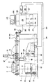
- control device is shown schematically and simply by way of example in the drawing in which the single figure is a view in elevation.
- the numerical control device shown is associated with a doll bar turning machine 1, movable longitudinally on a bench 2.
- This doll contains a spindle 3, which can be rotated by an asynchronous motor 4, housed in the base 5 of the bar turning machine.
- the mechanical connection between the motor 4 and the spindle 3 is carried out in a conventional manner, by belts 6, 7 and pulleys 8, 9, 10, the latter two being wedged on a shaft 11, also housed in the base 5.
- the spindle 3 is intended to drive a bar of material in rotation, the anterior end of the latter being engaged in a guide barrel (not shown) mounted in a vertical support 12. On the latter are also mounted tools (not shown) ) which are arranged as a fan and are fixed to slides 13 movable radially in the direction of the axis of the spindle 3, in order to shape the lateral face of the parts to be produced. Other tools (not shown) allow the front face to be machined.
- this bar turning machine is controlled by cams 14, wedged on a shaft 15.
- the latter is rotated from a speed reducer 16 by pulleys 17, 18 and a worm gear transmission 19.
- the input pulley 20 of the reduction gear 16 is driven by a pulley wedged on the shaft 11.
- the latter pulley is eliminated and a direct current motor 21 of the digital control device is mounted in the base 5.
- the cabinet 23 of the digital control device contains a memory 24, a frequency converter 27, an amplifier 28 and two correctors 29, each of which can be adjusted manually using the buttons 30, 31.
- a station 25 with keyboard 26 mounted on the cabinet 23, makes it possible to program the memory 24.
- the digital control device also comprises an encoder 32, which is connected to the camshaft 15 by the two pulleys 33, 34.
- the encoder 32 records at all times the angular position of the camshaft 15 and it transmits this information to the memory 24 by the line 35. At each angle traversed by the camshaft 15 during a revolution corresponds a function or operation of the bar turning machine, intended to produce a part: tightening of the material bar in the spindle 3, advancement and retreat of the headstock 1 and / or of one or more tools, cutting of the workpiece and loosening of the bar matter.
- the data fixed in the memory 24 using the keyboard 26 correspond to the speeds at which the spindle 3 and the camshaft 15 must rotate during each of the angles traversed by the shaft 15 during a complete revolution.
- the memory 24 is thus able to transmit instructions to the frequency converter 27 and to the amplifier 28 via its output lines 36 and 37.
- the frequency converter 27 is connected to the motor 4 by a line 38. According to the successive instructions received from the memory 24, the frequency converter 27 modifies the frequency of the current supplying the motor 4, so that the speed of rotation of this last change to the extent necessary to rotate spindle 3 at the desired speed following each new command transmitted by the frequency converter 27.
- the amplifier 28 is likewise connected to the motor 21 by a line 39. Depending on the successive instructions received from the memory 24, it modifies the power supply of the motor 21, which causes its rotation speed and therefore that of the 'camshaft 15. It should be noted that there are also AC motors whose speed of rotation can be modified by an amplifier. Currently, however, they are relatively expensive.
- the digital control device described allows the user to impose a determined speed of rotation both on the spindle 3 and on the shaft 15.
- the rotational speeds of the spindle 3 and / or of the shaft 15 can naturally be gradually modified.
- the correctors 29 remain out of service. If, on the contrary, the user is not sure of the speed at which the spindle 3 or the camshaft 15 or both must rotate during a determined machining phase, he can, using the keyboard 26, order memory 24 to activate one or the other or both correctors 29 for the duration of this machining phase.
- the first of the correctors 29 is connected at the start of line 36. If it has been activated by memory 24, its button 30 makes it possible to correct more or less the setpoint that the memory would otherwise transmit to the frequency converter 27.
- the second corrector 29 is likewise connected at the start of line 37 and its button 31 allows the setpoint transmitted to the amplifier 28 to be corrected in the same way.
- the frequency converter 27 and the amplifier 28 are, of course, chosen so that the speeds in question can be modified to a sufficient extent to find the optimal rotational speeds of spindle 3 and shaft 15 by a few tests carried out before starting production serial.
- the correction described using the buttons 30, 31 is naturally easier and above all faster than a correction made using the keyboard 26.
- the digital control device makes it possible to work with all the sets of cams that the user has in reserve.
Landscapes
- Engineering & Computer Science (AREA)
- Human Computer Interaction (AREA)
- Manufacturing & Machinery (AREA)
- Physics & Mathematics (AREA)
- General Physics & Mathematics (AREA)
- Automation & Control Theory (AREA)
- Turning (AREA)
- Numerical Control (AREA)
Claims (5)
- Numerische Steuervorrichtung zum Sicherstellen des Antriebs der Spindel des Spindelstocks und der Nockenwelle, die prinzipiell die Bewegungen des Spindelstocks und der dem Spindelstock einer automatischen Einspindeldrehmaschine zugeordneten Werkzeuge steuert, dadurch gekennzeichnet, daß sie für den Antrieb der Nockenwelle (15) einen Motor (21) gesondert von dem die Spindel (3) der Drehmaschine antreibenden aufweist, daß sie ferner einen mit der Nockenwelle (15) verbundenen Geber (32) umfaßt, der kontinuierlich den von der Nockenwelle vom Beginn jedes Zyklus an durchlaufenen Drehwinkel einem Speicher (24) übermittelt, daß der Speicher programmierbar und programmiert ist zum Liefern von zwei Führungsgrößen, bestimmt zum Laufenlassen der Spindel mit einer an die im Eingriff befindlichen Werkzeuge angepaßten Drehzahl und zum Vor- und Rücklaufenlassen des Spindelstocks und/oder der im Eingriff befindlichen Werkzeuge mit einer am besten an den jeweiligen Arbeitsgang angepaßten Geschwindigkeit, und daß zu diesem Zweck je nach den vom Geber (32) empfangenen Informationen diese Informationen auf den Speicher (24) derart einwirken, daß dieser gleichzeitig die richtige Führungsgröße zu dem die Spindel (3) antreibenden Motor (4) und die richtige Führungsgröße zu dem die Nockenwelle (15) antreibenden Motor (21) überträgt.
- Steuervorrichtung nach Anspruch 1, dadurch gekennzeichnet, daß sie eine Programmierstation (25) mit Tastenfeld (26) umfaßt, die es ermöglicht, den Speicher (24) in Abhängigkeit von der Art und Form der zu erzeugenden Werkstücke zu konditionieren.
- Steuervorrichtung nach Anspruch 1 oder 2, dadurch gekennzeichnet, daß der Speicher (24) seine Führungsgrößen zu dem Antriebsmotor (4) der Spindel (3) der Drehmaschine über einen Frequenzwandler (27) überträgt.
- Steuervorrichtung nach Anspruch 1, 2 oder 3, dadurch gekennzeichnet, daß der die Nockenwelle (15) antreibende Motor (21) ein Gleich- oder Wechselstrommotor ist und daß der Speicher ihm seine Führungsgrößen über einen Verstärker (28) zuführt.
- Steuervorrichtung nach Ansprüchen 3 und 4, dadurch gekenzeichnet, daß sie zwei Führungsgrößen-Korrigieranordnungen (29) mit Einstellknöpfen (30, 31) am Ausgang des Speichers (24) angeordnet umfaßt, die eine am Beginn der mit dem Frequenzwandler (27) verbundenen Leitung (36) und die andere am Beginn der mit dem Verstärker (28) verbundenen Leitung (37), und daß die Programmierstation (25) es ermöglicht, wahlweise zwischen irgendwelchen aufeinanderfolgenden Informationspaaren des Gebers (32) die Inbetriebnahme der Korrigieranordnungen (29) sicherzustellen, welche letzteren es ermöglichen, unabhängig voneinander in manuell einstellbarer Proportion die Führungsgrößen des Speichers für den Frequenzwandler (27) bzw. für den Verstärker (28) zu modifizieren.
Applications Claiming Priority (2)
| Application Number | Priority Date | Filing Date | Title |
|---|---|---|---|
| CH1856/85A CH658820A5 (fr) | 1985-05-02 | 1985-05-02 | Dispositif de commande numerique pour tour automatique. |
| CH1856/85 | 1985-05-02 |
Publications (2)
| Publication Number | Publication Date |
|---|---|
| EP0200687A1 EP0200687A1 (de) | 1986-11-05 |
| EP0200687B1 true EP0200687B1 (de) | 1991-10-16 |
Family
ID=4220206
Family Applications (1)
| Application Number | Title | Priority Date | Filing Date |
|---|---|---|---|
| EP86810194A Expired - Lifetime EP0200687B1 (de) | 1985-05-02 | 1986-04-30 | Verfahren zur Steuerung eines automatischen Drehautomaten |
Country Status (5)
| Country | Link |
|---|---|
| US (1) | US4656897A (de) |
| EP (1) | EP0200687B1 (de) |
| JP (1) | JPS61293704A (de) |
| CH (1) | CH658820A5 (de) |
| DE (1) | DE3681955D1 (de) |
Families Citing this family (15)
| Publication number | Priority date | Publication date | Assignee | Title |
|---|---|---|---|---|
| JPH0277903A (ja) * | 1988-09-14 | 1990-03-19 | Fanuc Ltd | 数値制御方法 |
| JP2722404B2 (ja) * | 1989-03-30 | 1998-03-04 | 野村精機株式会社 | 主軸移動型自動旋盤 |
| AT394509B (de) * | 1989-09-11 | 1992-04-27 | Steinel Gmbh Voest Alpine | Von hand steuerbare drehmaschine |
| US5319288A (en) * | 1989-10-06 | 1994-06-07 | Fanuc Ltd | Main spindle rotation control method |
| US6205372B1 (en) | 1993-07-28 | 2001-03-20 | Thurston/Amt Partnership | System for adapting an automatic screw machine control achieve computer numeric control |
| US5808893A (en) * | 1993-07-28 | 1998-09-15 | Amt Machine Systems, Ltd. | System for adapting an automatic screw machine to achieve computer numeric control |
| EP0783389B1 (de) * | 1993-07-28 | 2002-04-17 | Thurston/Amt Partnership | Transformationssystem für automatische drehmaschinen in maschinen mit computernumerischer steuerung |
| US5526725A (en) * | 1994-03-23 | 1996-06-18 | Tremaglio; Neil L. | Rapid indexing spindle drive attachment for CAM controlled automatic screw machines |
| FR2742372B1 (fr) * | 1995-12-13 | 1998-01-30 | Etude Realisations Representat | Dispositif de deplacement d'une broche d'une machine outil |
| US6035707A (en) * | 1996-12-19 | 2000-03-14 | Main; Scott | Camshaft bench tester |
| AU2341900A (en) | 1998-09-03 | 2000-04-10 | Lockheed Martin Corporation | Automated fuel tank assembly system and method |
| GB9912893D0 (en) * | 1999-06-04 | 1999-08-04 | Unova Uk Ltd | Surface forming of metal components |
| GB201014039D0 (en) | 2010-08-23 | 2010-10-06 | Sandvik Ltd | Method for machining a workpiece |
| CN109807645B (zh) * | 2019-03-20 | 2024-08-23 | 张家港名阳精密机械制造有限公司 | 自动车床的调速控制机构 |
| CN118143302B (zh) * | 2024-03-28 | 2024-11-22 | 广东中海万泰技术有限公司 | 车床的控制方法、控制装置及车床 |
Family Cites Families (13)
| Publication number | Priority date | Publication date | Assignee | Title |
|---|---|---|---|---|
| US3656377A (en) * | 1969-07-10 | 1972-04-18 | Allen Bradley Co | Surface speed control of spindle-related numerical control system |
| DE2300249B2 (de) * | 1973-01-04 | 1975-07-17 | Gildemeister Ag, 4800 Bielefeld | Mehrspindel-Drehautomat |
| US4120185A (en) * | 1975-01-16 | 1978-10-17 | L. Schuler Gmbh | Control system for operating steps of a press and/or transfer mechanism |
| US4106375A (en) * | 1975-04-18 | 1978-08-15 | Litton Industrial Products, Inc. | Variable feed high-production precision machine |
| US3978745A (en) * | 1975-05-27 | 1976-09-07 | Citizen Watch Co., Ltd. | Numerically controlled automatic lathe |
| US3976861A (en) * | 1975-06-27 | 1976-08-24 | General Electric Company | Apparatus for maintaining a constant surface speed of a rotating work piece being cut by a moving cutting tool |
| JPS536389A (en) * | 1976-07-07 | 1978-01-20 | Res Inst For Prod Dev | Manufacture of resin composites |
| DE2732354C3 (de) * | 1977-07-18 | 1981-09-10 | Goetze Ag, 5093 Burscheid | Drehmaschine für die Unrundbearbeitung, insbesondere von Kolbenringen |
| JPS569148A (en) * | 1979-06-30 | 1981-01-30 | Fanuc Ltd | Controlling method for constant circumferential speed |
| US4267495A (en) * | 1979-10-05 | 1981-05-12 | Cone-Blanchard Machine Company | Machine speed controller |
| US4253359A (en) * | 1979-10-24 | 1981-03-03 | Cone-Blanchard Machine Company | Drive system for multiple spindle machine tool |
| JPS6043266B2 (ja) * | 1979-11-12 | 1985-09-27 | ファナック株式会社 | 電動機駆動制御方式 |
| JPS59174914A (ja) * | 1983-03-24 | 1984-10-03 | Matsushita Electric Ind Co Ltd | カム式精密旋盤の制御装置 |
-
1985
- 1985-05-02 CH CH1856/85A patent/CH658820A5/fr not_active IP Right Cessation
-
1986
- 1986-04-29 US US06/857,002 patent/US4656897A/en not_active Expired - Fee Related
- 1986-04-30 DE DE8686810194T patent/DE3681955D1/de not_active Expired - Fee Related
- 1986-04-30 JP JP61098401A patent/JPS61293704A/ja active Pending
- 1986-04-30 EP EP86810194A patent/EP0200687B1/de not_active Expired - Lifetime
Also Published As
| Publication number | Publication date |
|---|---|
| DE3681955D1 (de) | 1991-11-21 |
| US4656897A (en) | 1987-04-14 |
| JPS61293704A (ja) | 1986-12-24 |
| EP0200687A1 (de) | 1986-11-05 |
| CH658820A5 (fr) | 1986-12-15 |
Similar Documents
| Publication | Publication Date | Title |
|---|---|---|
| EP0200687B1 (de) | Verfahren zur Steuerung eines automatischen Drehautomaten | |
| KR100795470B1 (ko) | 고속 연마기능을 갖는 터닝가공장치 및 그 제어방법 | |
| FR2558401A1 (fr) | Machine-outil capable d'executer des operations d'usinage de differents types, tels que tournage, fraisage et percage | |
| JPS614660A (ja) | ホーニング工具の送り方法および装置 | |
| FR2565139A1 (fr) | Machine-outil a deux broches porte-piece | |
| FR2520891A1 (fr) | Procede pour commander la modification d'un programme d'usinage dans une machine-outil a commande numerique | |
| JPH02292147A (ja) | 位相割出し方法 | |
| JPH11188557A (ja) | 自動工具交換装置の交換速度制御方法及び制御装置 | |
| CA1331909C (fr) | Tour automatique destine a usiner de la matiere en torche | |
| US2222206A (en) | Turning and milling machine | |
| CN209936353U (zh) | 自动车床的调速控制机构 | |
| CN210172979U (zh) | 一种快开慢开阀芯一体专用机床 | |
| CN215847140U (zh) | 一种cnc加工中心刀具旋拧工装 | |
| CN114653979A (zh) | 一种便于轴类工件加工的数控机床 | |
| JP3349588B2 (ja) | Nc自動旋盤のガイドブッシュ調整方法 | |
| US20030118418A1 (en) | NC helical broaching machine improved in broach driving | |
| JP3071016B2 (ja) | 複合加工装置 | |
| CN220240071U (zh) | 一种可自动加工的机床 | |
| CN109807645B (zh) | 自动车床的调速控制机构 | |
| JPH07328804A (ja) | Nc自動旋盤のガイドブッシュ調整方法及びその装置 | |
| JPH0323281B2 (de) | ||
| JP2521530B2 (ja) | 回転差制御装置付複合nc旋盤及びこれによる加工方法 | |
| JP3792566B2 (ja) | 歯車研削方法および歯車研削装置 | |
| JP2574416B2 (ja) | 工作機 | |
| JPS639377Y2 (de) |
Legal Events
| Date | Code | Title | Description |
|---|---|---|---|
| PUAI | Public reference made under article 153(3) epc to a published international application that has entered the european phase |
Free format text: ORIGINAL CODE: 0009012 |
|
| AK | Designated contracting states |
Kind code of ref document: A1 Designated state(s): CH DE FR GB IT LI |
|
| 17P | Request for examination filed |
Effective date: 19870430 |
|
| 17Q | First examination report despatched |
Effective date: 19871204 |
|
| GRAA | (expected) grant |
Free format text: ORIGINAL CODE: 0009210 |
|
| AK | Designated contracting states |
Kind code of ref document: B1 Designated state(s): CH DE FR GB IT LI |
|
| PG25 | Lapsed in a contracting state [announced via postgrant information from national office to epo] |
Ref country code: IT Free format text: LAPSE BECAUSE OF FAILURE TO SUBMIT A TRANSLATION OF THE DESCRIPTION OR TO PAY THE FEE WITHIN THE PRE;WARNING: LAPSES OF ITALIAN PATENTS WITH EFFECTIVE DATE BEFORE 2007 MAY HAVE OCCURRED AT ANY TIME BEFORE 2007. THE CORRECT EFFECTIVE DATE MAY BE DIFFERENT FROM THE ONE RECORDED.SCRIBED TIME-LIMIT Effective date: 19911016 Ref country code: GB Effective date: 19911016 |
|
| REF | Corresponds to: |
Ref document number: 3681955 Country of ref document: DE Date of ref document: 19911121 |
|
| GBV | Gb: ep patent (uk) treated as always having been void in accordance with gb section 77(7)/1977 [no translation filed] | ||
| PLBE | No opposition filed within time limit |
Free format text: ORIGINAL CODE: 0009261 |
|
| STAA | Information on the status of an ep patent application or granted ep patent |
Free format text: STATUS: NO OPPOSITION FILED WITHIN TIME LIMIT |
|
| 26N | No opposition filed | ||
| PGFP | Annual fee paid to national office [announced via postgrant information from national office to epo] |
Ref country code: CH Payment date: 19930419 Year of fee payment: 8 |
|
| PGFP | Annual fee paid to national office [announced via postgrant information from national office to epo] |
Ref country code: DE Payment date: 19930420 Year of fee payment: 8 |
|
| REG | Reference to a national code |
Ref country code: CH Ref legal event code: AEN |
|
| REG | Reference to a national code |
Ref country code: CH Ref legal event code: PL |
|
| PGFP | Annual fee paid to national office [announced via postgrant information from national office to epo] |
Ref country code: FR Payment date: 19940414 Year of fee payment: 9 |
|
| PG25 | Lapsed in a contracting state [announced via postgrant information from national office to epo] |
Ref country code: CH Effective date: 19940430 Ref country code: LI Effective date: 19940430 |
|
| PG25 | Lapsed in a contracting state [announced via postgrant information from national office to epo] |
Ref country code: DE Effective date: 19950103 |
|
| PG25 | Lapsed in a contracting state [announced via postgrant information from national office to epo] |
Ref country code: FR Effective date: 19951229 |
|
| REG | Reference to a national code |
Ref country code: FR Ref legal event code: ST |