EP0200844A1 - Marteau perforateur - Google Patents
Marteau perforateur Download PDFInfo
- Publication number
- EP0200844A1 EP0200844A1 EP85810592A EP85810592A EP0200844A1 EP 0200844 A1 EP0200844 A1 EP 0200844A1 EP 85810592 A EP85810592 A EP 85810592A EP 85810592 A EP85810592 A EP 85810592A EP 0200844 A1 EP0200844 A1 EP 0200844A1
- Authority
- EP
- European Patent Office
- Prior art keywords
- drive
- drive motor
- striking mechanism
- rotary
- tool
- Prior art date
- Legal status (The legal status is an assumption and is not a legal conclusion. Google has not performed a legal analysis and makes no representation as to the accuracy of the status listed.)
- Granted
Links
- 230000008878 coupling Effects 0.000 claims abstract description 17
- 238000010168 coupling process Methods 0.000 claims abstract description 17
- 238000005859 coupling reaction Methods 0.000 claims abstract description 17
- 230000033001 locomotion Effects 0.000 description 6
- 238000009527 percussion Methods 0.000 description 5
- 238000005553 drilling Methods 0.000 description 4
- 230000000694 effects Effects 0.000 description 2
- 238000000034 method Methods 0.000 description 2
- 239000000758 substrate Substances 0.000 description 2
- 230000005540 biological transmission Effects 0.000 description 1
- 238000009434 installation Methods 0.000 description 1
- 239000000463 material Substances 0.000 description 1
- 238000005065 mining Methods 0.000 description 1
- 238000007789 sealing Methods 0.000 description 1
- 239000002023 wood Substances 0.000 description 1
Images

Classifications
-
- F—MECHANICAL ENGINEERING; LIGHTING; HEATING; WEAPONS; BLASTING
- F16—ENGINEERING ELEMENTS AND UNITS; GENERAL MEASURES FOR PRODUCING AND MAINTAINING EFFECTIVE FUNCTIONING OF MACHINES OR INSTALLATIONS; THERMAL INSULATION IN GENERAL
- F16H—GEARING
- F16H37/00—Combinations of mechanical gearings, not provided for in groups F16H1/00 - F16H35/00
- F16H37/12—Gearings comprising primarily toothed or friction gearing, links or levers, and cams, or members of at least two of these types
- F16H37/14—Gearings comprising primarily toothed or friction gearing, links or levers, and cams, or members of at least two of these types the movements of two or more independently-moving members being combined into a single movement
-
- B—PERFORMING OPERATIONS; TRANSPORTING
- B25—HAND TOOLS; PORTABLE POWER-DRIVEN TOOLS; MANIPULATORS
- B25D—PERCUSSIVE TOOLS
- B25D16/00—Portable percussive machines with superimposed rotation, the rotational movement of the output shaft of a motor being modified to generate axial impacts on the tool bit
- B25D16/003—Clutches specially adapted therefor
-
- B—PERFORMING OPERATIONS; TRANSPORTING
- B25—HAND TOOLS; PORTABLE POWER-DRIVEN TOOLS; MANIPULATORS
- B25D—PERCUSSIVE TOOLS
- B25D2211/00—Details of portable percussive tools with electromotor or other motor drive
- B25D2211/003—Crossed drill and motor spindles
-
- B—PERFORMING OPERATIONS; TRANSPORTING
- B25—HAND TOOLS; PORTABLE POWER-DRIVEN TOOLS; MANIPULATORS
- B25D—PERCUSSIVE TOOLS
- B25D2211/00—Details of portable percussive tools with electromotor or other motor drive
- B25D2211/06—Means for driving the impulse member
- B25D2211/068—Crank-actuated impulse-driving mechanisms
-
- B—PERFORMING OPERATIONS; TRANSPORTING
- B25—HAND TOOLS; PORTABLE POWER-DRIVEN TOOLS; MANIPULATORS
- B25D—PERCUSSIVE TOOLS
- B25D2250/00—General details of portable percussive tools; Components used in portable percussive tools
- B25D2250/275—Tools having at least two similar components
- B25D2250/281—Double motors
-
- Y—GENERAL TAGGING OF NEW TECHNOLOGICAL DEVELOPMENTS; GENERAL TAGGING OF CROSS-SECTIONAL TECHNOLOGIES SPANNING OVER SEVERAL SECTIONS OF THE IPC; TECHNICAL SUBJECTS COVERED BY FORMER USPC CROSS-REFERENCE ART COLLECTIONS [XRACs] AND DIGESTS
- Y10—TECHNICAL SUBJECTS COVERED BY FORMER USPC
- Y10T—TECHNICAL SUBJECTS COVERED BY FORMER US CLASSIFICATION
- Y10T74/00—Machine element or mechanism
- Y10T74/19—Gearing
- Y10T74/19023—Plural power paths to and/or from gearing
- Y10T74/19051—Single driven plural drives
-
- Y—GENERAL TAGGING OF NEW TECHNOLOGICAL DEVELOPMENTS; GENERAL TAGGING OF CROSS-SECTIONAL TECHNOLOGIES SPANNING OVER SEVERAL SECTIONS OF THE IPC; TECHNICAL SUBJECTS COVERED BY FORMER USPC CROSS-REFERENCE ART COLLECTIONS [XRACs] AND DIGESTS
- Y10—TECHNICAL SUBJECTS COVERED BY FORMER USPC
- Y10T—TECHNICAL SUBJECTS COVERED BY FORMER US CLASSIFICATION
- Y10T74/00—Machine element or mechanism
- Y10T74/19—Gearing
- Y10T74/19023—Plural power paths to and/or from gearing
- Y10T74/19126—Plural drivers plural driven
Definitions
- the invention relates to a hammer drill, in which a tool is optionally given rotation, strikes or rotation and strikes by means of a striking mechanism and a rotary drive device, with two independently controllable drive motors, the first of which is coupled to the striking mechanism and the second to the rotary drive device.
- a known hammer drill (DE-OS 31 42 740) has two independently controllable drive motors for this purpose, the first of which actuates a striking mechanism and the second of which actuates a rotary drive device.
- each drive motor is designed for the maximum power in the respective operating mode, which requires relatively large motors.
- the invention has for its object to provide a hammer drill with two drive motors for a striking mechanism and a rotary drive device, the hammer mechanism and rotary drive device are individually controllable and the drive motors are characterized by a comparatively small dimension.
- the object is achieved in that between the drive chain connecting the first drive motor with the striking mechanism and the drive chain connecting the second drive motor with the rotary drive device, a force flow from one drive chain to the other is provided.
- the coupling device is expediently a gear part which mechanically connects the drive chains of the drive motors to one another.
- the drive motors can support each other through the power flow between the drive chains.
- the first drive motor coupled to the striking mechanism feeds the rotary drive device when there is an increased power requirement.
- the coupling device is advantageously designed as a planetary gear.
- the epicyclic gearbox preferably has two planet gears, which mesh on the one hand with an output shaft of the first motor and on the other hand with a ring gear that can be rotated concentrically to the output shaft.
- the axis of the planet gears can be rotated about its own axis in a carrier, which is in turn rotatably mounted to the output shaft of the first motor.
- the driving force of the first, the second or both drive motors acts on the planet gears.
- the drive motors actuate the striking mechanism and the rotary drive device via the epicyclic gear, whereby a force flow for mutual support of the motors occurs due to the coupling connection created by the epicyclic gear between the drive chains emanating from the two drive motors.
- the second drive motor provided primarily for the rotary drive device can be dimensioned considerably smaller than the first drive motor, ie, for example, have about 30% of the performance of the first motor.
- the clutch device is preferably designed as a one-way clutch. It can be a one-way clutch of conventional design.
- Such one-way clutches consist of two coupling halves - a driving and an aborting part - between which coupling members are arranged. Due to the relative direction of rotation of the two coupling halves, the one-way clutch is switched, that is to say entrainment in one direction of movement and free-wheeling in the other. Clamping rollers, for example, are suitable as coupling members.
- a clutch device in the form of a one-way clutch is characterized in particular by the simplicity of the structure of the clutch and the installation of the clutch between the drive chains.
- the one-way clutch sits on an output shaft of the drive chain connected to the first drive motor.
- the first drive motor provided for the striking mechanism is from the striking mechanism relatively evenly loaded, while the second drive motor provided for the rotary drive device is subject to a continuously changing power requirement during the drilling process.
- the changing power requirement of the rotary drive device results from the changing friction conditions of the tool in the borehole during the drilling process and from the different material conditions of the substrate.
- the overrunning clutch has a clutch gearwheel which meshes with an intermediate gearwheel in the drive chain between the second drive motor and the rotary drive device.
- the power flow that can be achieved in this way has the effect that the output shaft of the first drive motor can be overhauled by the clutch gear, so that the rotational speed for the tool is increased with the aid of the second drive motor beyond the speed that can be achieved with the first drive motor. If the rotational speed of the second drive motor drops due to the increased torque required for the rotation of the tool, the first drive motor engages automatically via the one-way clutch to support the rotary drive.
- the freewheeling direction of rotation of the clutch gear wheel expediently runs in the opposite direction to the drive direction of rotation of the intermediate gear wheel.
- the second drive motor which effects the rotary drive of the tool always runs in the direction of rotation which is ideal for the drilling tool. This applies both when the tool is only rotating and when the tool is rotating and striking.
- the operating mode which only delivers blows to the tool is achieved in a simple manner by reversing the direction of rotation of the first drive motor compared to the other operating modes.
- the one-way clutch takes on the one-way position.
- the operating mode that only delivers rotation to the tool there may be applications (e.g. drilling in wood) in which a particularly high torque and a higher tool speed than is required, for example, in concrete processing are required. In this case, it is advisable to switch off the striking mechanism in the drive chain leading to the striking mechanism. With the striking mechanism switched off, it is possible to ramp up the first drive motor to its maximum speed. Both drive motors then act together on the rotary drive device.
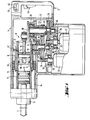
- the hammer drill can impart rotation, strikes or rotation and strikes to a tool 4 held in a tool holder 3.
- the rotation is transmitted to the tool 4 via driver elements in the tool holder 3 which are known per se and are therefore not shown in detail.
- the tool holder 3 stands with a rotatable guide cylinder 5 in connection.
- On the guide cylinder 5 sits a ring gear 6 with bevel gear, which together with the guide cylinder 5 and the tool holder 3 represents a rotary drive device, designated overall by 7.
- the tool 4 protrudes with the rear end into the guide cylinder 5 and thus into the effective range of a striking mechanism, designated overall by 8.
- the rotationally fixed connection of the ring gear 6 on the guide cylinder 5 is ensured by a spring 9 projecting into the longitudinal grooves of both parts.
- Circlips 11, 12 fix the ring gear 6 on the guide cylinder 5 immovably.
- the ring gear 6 and thus also the guide cylinder 5 are rotatably supported in the housing 1 via a roller bearing 13.
- a sleeve 14 supports the roller bearing 13 from the front.
- the striking mechanism 8 has a striking piston 15 and a driving piston 16, both of which are displaceably mounted in a sealing manner in the guide cylinder 5. Air is located in the space formed between the two pistons in the guide cylinder 5 and is compressed and decompressed alternately when the drive piston 16 moves back and forth due to the inertia of the percussion piston 15.
- the pressure change of this air also causes a reciprocating movement of the percussion piston 15, the forward stroke of which is always stopped by striking the tool 4. Bores 17 in the guide cylinder 5 make it possible to stop the percussion piston 15 when it moves further forward in the guide cylinder 5 with the tool 4 removed.
- the lifting movement of the driving piston 16 is generated by a connecting rod 18, which is articulated at one end via a transverse pin 19 on the driving piston 16 and is in drive connection with a crank 20 at the second end.
- a strikingly recognizable first drive motor 21 is connected to the striking mechanism 8. Its rotor shaft 22 is guided on the housing side via a roller bearing 23 and has a toothing 24 in the end region.
- the drive chain between the drive motor 21 and the striking mechanism 8 has a gear 25 which meshes with the toothing 24 and which is non-rotatably seated on an output shaft 26 which in turn is firmly connected to the crank 20.
- a spring 27 accomplishes the rotational fixation of the gear 25 on the output shaft 26.
- the latter is rotatably supported in the housing parts via a slide bearing 28 and via a roller bearing 29.
- a second drive motor 31 which can be recognized as indicated, is primarily provided.
- Whose rotor shaft 32 is in turn guided on the housing side via a roller bearing 33 and has a toothing 34.
- An intermediate gear 35 which meshes with the rotor shaft 32 is provided in the drive chain between the second drive motor 31 and the rotary drive device 7.
- the latter sits on a shaft 36 in a rotationally fixed manner.
- a spring 37 creates the rotationally fixed connection between the two parts.
- the shaft 36 is rotatably supported on the housing side via a slide bearing 38 and a roller bearing 39.
- a bevel gear 41 on the shaft 36 meshes with the bevel gear 42 of the ring gear 6.
- a one-way clutch designated 43.
- This consists essentially of symbolically indicated coupling members 44 of conventional design, which bring about the same directional rotation of a coupling gear 45 in only one direction of rotation of the drive shaft 26.
- the clutch gear 45 always meshes with the intermediate gear 35.
- the handle 2 has an on / off switch 48, by means of which the device can be put into operation. Furthermore, control switches are provided in the handle for independently controlling the rotational speed of the drive motors 21, 31, the control switch 49 provided for the drive motor 21 being visible. By moving the control switches, the appropriate speeds of the drive motors 21, 31 can be set in accordance with a stationary symbol 51.
- the drive motor 31 is put into operation at the appropriate speed.
- the rotary movement is transmitted from the rotor shaft 32 via the intermediate gear 35 and the shaft 36 to the rotary drive device 7.
- the intermediate gear 35 rotates the clutch gear 45 freely.
- Both drive motors 21, 31 are put into operation to impart rotation and impacts to the tool 4.
- the power flow is such that the output shaft 26 can be overtaken by the clutch gear 45.
- the speed of the tool 4 can therefore be increased with the help of the drive motor 31 beyond the speed that the drive motor 21 brings.
- the drive motor 21 engages via the one-way clutch 43 to support the rotary drive.
- the drive motor 21 For the exclusive transmission of impacts to the tool 4, only the drive motor 21 is put into operation - in contrast to the other operating modes with the direction of rotation reversed - as a result of which the overrunning clutch 43 decouples the output shaft 26 from the drive chain of the rotary drive device 7.
- the impact power can be set by selecting the corresponding spindle speed of the drive motor 21 via the control switch 49.
- FIG. 2 again shows a guide cylinder 61 with a ring gear 62, which has a bevel gear 63.
- the ring gear 62 is non-rotatably connected to the guide cylinder 61 by a spring 64.
- the guide cylinder 61 and the ring gear 62 are in turn parts of a rotary drive device, designated overall by 65.
- a percussion piston 66 and a driving piston 67 are slidably mounted in the guide cylinder 61.
- a connecting rod 68 engages on the driving piston 67 and is set in motion by a crank 69.
- Percussion pistons 66, driving pistons 67, connecting rods 68 and crank 69 together form a striking mechanism, designated overall by 71.
- a toothed wheel 72 To drive the crank 69, it is connected to a toothed wheel 72. The latter meshes with the toothing of a rotor shaft 73 of a drive motor, not shown in detail. Concentrically to the rotor shaft 73, a drive wheel 74 is mounted so that it can rotate freely. This is in engagement with the bevel gear 63 of the ring gear 62 via a bevel gear 75.
- the driving wheel 74 also has an external toothing 76 with which two diametrically opposed planet wheels 77, 77 'mesh. Another larger ring gear 78, 78 'or planet gears 77, 77' meshes with a toothing 79 on the rotor shaft 73.
- the support wheel 81 in turn is rotatable about the axis of the rotor shaft 73. Via an external toothing 82, the support wheel 81 is in engagement with the rotor shaft 83 of a second drive motor, not shown in detail.
- the striking mechanism 71 is driven via the rotor shaft 73.
- the rotation of the rotor shaft 73 causes the planet gears 77, 77 'and the drive wheel 74 simultaneously actuates the rotary drive device 65.
- the support wheel 81 and thus also the drive wheel 74 are driven via the rotor shaft 83.
- the two rotary movements initiated on the drive wheel 74 by the two drive motors add or subtract - depending on the direction of rotation of the rotor shafts 73, 83. In this way, any speed between the two limit values can be set for the tool.
Landscapes
- Engineering & Computer Science (AREA)
- Mechanical Engineering (AREA)
- General Engineering & Computer Science (AREA)
- Percussive Tools And Related Accessories (AREA)
- Valve-Gear Or Valve Arrangements (AREA)
- Earth Drilling (AREA)
- Saccharide Compounds (AREA)
- Electrical Discharge Machining, Electrochemical Machining, And Combined Machining (AREA)
- Drilling Tools (AREA)
- Catalysts (AREA)
- Ceramic Products (AREA)
- Drilling And Boring (AREA)
- Surgical Instruments (AREA)
- Harvester Elements (AREA)
Priority Applications (1)
| Application Number | Priority Date | Filing Date | Title |
|---|---|---|---|
| AT85810592T ATE34322T1 (de) | 1985-05-08 | 1985-12-12 | Bohrhammer. |
Applications Claiming Priority (2)
| Application Number | Priority Date | Filing Date | Title |
|---|---|---|---|
| DE3516494 | 1985-05-08 | ||
| DE19853516494 DE3516494A1 (de) | 1985-05-08 | 1985-05-08 | Bohrhammer |
Publications (2)
| Publication Number | Publication Date |
|---|---|
| EP0200844A1 true EP0200844A1 (fr) | 1986-11-12 |
| EP0200844B1 EP0200844B1 (fr) | 1988-05-18 |
Family
ID=6270113
Family Applications (1)
| Application Number | Title | Priority Date | Filing Date |
|---|---|---|---|
| EP85810592A Expired EP0200844B1 (fr) | 1985-05-08 | 1985-12-12 | Marteau perforateur |
Country Status (11)
| Country | Link |
|---|---|
| US (1) | US4732218A (fr) |
| EP (1) | EP0200844B1 (fr) |
| JP (1) | JPS6215085A (fr) |
| AT (1) | ATE34322T1 (fr) |
| AU (1) | AU575251B2 (fr) |
| CA (1) | CA1248782A (fr) |
| DE (2) | DE3516494A1 (fr) |
| DK (1) | DK212686A (fr) |
| ES (1) | ES8706498A1 (fr) |
| FI (1) | FI861773A7 (fr) |
| YU (1) | YU17786A (fr) |
Cited By (1)
| Publication number | Priority date | Publication date | Assignee | Title |
|---|---|---|---|---|
| WO2011026683A1 (fr) * | 2009-09-01 | 2011-03-10 | Robert Bosch Gmbh | Dispositif à marteau perforateur et/ou à marteau burineur |
Families Citing this family (28)
| Publication number | Priority date | Publication date | Assignee | Title |
|---|---|---|---|---|
| DE3839007C1 (fr) * | 1988-11-18 | 1989-12-07 | Turmag Turbo-Maschinen-Ag Nuesse & Graefer, 4322 Sprockhoevel, De | |
| US5020606A (en) * | 1988-12-27 | 1991-06-04 | Rockwell International Corporation | Reciprocating rotary tool driver |
| DE4013512A1 (de) * | 1990-04-27 | 1991-10-31 | Black & Decker Inc | Schalteinrichtung zum umschalten eines kraftgetriebenen werkzeugs |
| IT1244518B (it) * | 1991-01-18 | 1994-07-15 | Transtyle Ltd | Gruppo motore per il comando di una macchina atta alla produzione di prodotti alimentari pastosi e/o a comportamento fluido |
| DE59206059D1 (de) * | 1992-08-13 | 1996-05-23 | Kaba Schliesssysteme Ag | Sperrwerk für eine Sicherheitstüre |
| US5730230A (en) * | 1995-08-15 | 1998-03-24 | Sisler; John S. | Rotary percussion drill |
| DE19540396A1 (de) * | 1995-10-30 | 1997-05-07 | Hilti Ag | Bohr- und/oder Meisselgerät |
| JP3609626B2 (ja) * | 1998-09-16 | 2005-01-12 | 株式会社マキタ | ハンマードリル |
| AU751720B2 (en) | 1998-09-18 | 2002-08-22 | Stanley Fastening Systems, L.P. | Multi-stroke fastening device |
| DE10111748A1 (de) * | 2001-03-12 | 2002-09-19 | Hilti Ag | Schaltwerk für ein kombiniertes Handwerkzeuggerät |
| DE10213093B4 (de) * | 2002-03-23 | 2013-06-20 | Andreas Stihl Ag & Co. | Handbohrmaschine mit einem Verbrennungsmotor |
| GB0311045D0 (en) * | 2003-05-14 | 2003-06-18 | Black & Decker Inc | Rotary hammer |
| DE102004047606A1 (de) * | 2004-09-30 | 2006-04-06 | Hilti Ag | Bohr- und/oder Meisselhammer |
| US7469752B2 (en) * | 2005-12-02 | 2008-12-30 | Makita Corporation | Power tool |
| US9193053B2 (en) | 2008-09-25 | 2015-11-24 | Black & Decker Inc. | Hybrid impact tool |
| US9592600B2 (en) | 2011-02-23 | 2017-03-14 | Ingersoll-Rand Company | Angle impact tools |
| US8925646B2 (en) | 2011-02-23 | 2015-01-06 | Ingersoll-Rand Company | Right angle impact tool |
| JP2012171063A (ja) * | 2011-02-23 | 2012-09-10 | Hitachi Koki Co Ltd | 打撃工具 |
| US9630307B2 (en) | 2012-08-22 | 2017-04-25 | Milwaukee Electric Tool Corporation | Rotary hammer |
| DE102013202000A1 (de) * | 2013-02-07 | 2014-08-07 | Hilti Aktiengesellschaft | Werkzeugmaschine |
| US9022888B2 (en) | 2013-03-12 | 2015-05-05 | Ingersoll-Rand Company | Angle impact tool |
| EP3181303A1 (fr) * | 2015-12-14 | 2017-06-21 | HILTI Aktiengesellschaft | Procédé de commande et machine-outil manuelle |
| EP3854532A1 (fr) * | 2019-08-19 | 2021-07-28 | Hilti Aktiengesellschaft | Machine-outil, outil et système de machine-outil à un certain rapport de vitesse de rotation et de puissance de percussion |
| EP3789162A1 (fr) * | 2019-09-04 | 2021-03-10 | Hilti Aktiengesellschaft | Entraînement rotatif pour une machine-outil mainuelle |
| US11529727B2 (en) | 2019-10-21 | 2022-12-20 | Makita Corporation | Power tool having hammer mechanism |
| CN112247915A (zh) * | 2020-11-11 | 2021-01-22 | 江苏铁锚工具有限公司 | 双马达交直流无刷电锤 |
| US11819968B2 (en) | 2021-01-19 | 2023-11-21 | Milwaukee Electric Tool Corporation | Rotary power tool |
| JP7704580B2 (ja) * | 2021-06-10 | 2025-07-08 | 株式会社マキタ | 回転打撃工具 |
Citations (3)
| Publication number | Priority date | Publication date | Assignee | Title |
|---|---|---|---|---|
| US2792723A (en) * | 1952-10-11 | 1957-05-21 | Fischer Ag Georg | Continuous controllable two motor drive |
| FR2146732A5 (fr) * | 1971-07-21 | 1973-03-02 | Hilti Ag | |
| EP0021881A1 (fr) * | 1979-06-25 | 1981-01-07 | The Bendix Corporation | Démarreur de moteur et appareil d'entraînement d'accessoires |
Family Cites Families (7)
| Publication number | Priority date | Publication date | Assignee | Title |
|---|---|---|---|---|
| US2154591A (en) * | 1936-03-18 | 1939-04-18 | Air Equipment Sa | Driving mechanism |
| DE2729596A1 (de) * | 1977-06-30 | 1979-01-11 | Hilti Ag | Bohrhammer mit pneumatisch angetriebenem schlagkolben |
| US4568289A (en) * | 1978-08-24 | 1986-02-04 | Bhs-Bayerische Berg-, Hutten-Und Salzwerke | Marine transmission gear unit with double drive |
| US4579019A (en) * | 1980-04-04 | 1986-04-01 | Darcy Gabriele | Method and apparatus for power transmission from an engine |
| AT372639B (de) * | 1980-11-06 | 1983-10-25 | Hilti Ag | Schlagbohrmaschine |
| DE3045093A1 (de) * | 1980-11-29 | 1982-07-01 | Daimler-Benz Ag, 7000 Stuttgart | Mehrfachanordnung von brennkraftmaschinen |
| US4462467A (en) * | 1981-11-09 | 1984-07-31 | Hilti Aktiengesellschaft | Percussion drill machine |
-
1985
- 1985-05-08 DE DE19853516494 patent/DE3516494A1/de not_active Withdrawn
- 1985-12-12 DE DE8585810592T patent/DE3562723D1/de not_active Expired
- 1985-12-12 EP EP85810592A patent/EP0200844B1/fr not_active Expired
- 1985-12-12 AT AT85810592T patent/ATE34322T1/de not_active IP Right Cessation
-
1986
- 1986-02-07 YU YU00177/86A patent/YU17786A/xx unknown
- 1986-04-18 AU AU56375/86A patent/AU575251B2/en not_active Ceased
- 1986-04-28 FI FI861773A patent/FI861773A7/fi not_active Application Discontinuation
- 1986-05-05 US US06/859,647 patent/US4732218A/en not_active Expired - Fee Related
- 1986-05-07 DK DK212686A patent/DK212686A/da not_active Application Discontinuation
- 1986-05-07 JP JP61103238A patent/JPS6215085A/ja active Pending
- 1986-05-08 ES ES554761A patent/ES8706498A1/es not_active Expired
- 1986-05-08 CA CA000508710A patent/CA1248782A/fr not_active Expired
Patent Citations (3)
| Publication number | Priority date | Publication date | Assignee | Title |
|---|---|---|---|---|
| US2792723A (en) * | 1952-10-11 | 1957-05-21 | Fischer Ag Georg | Continuous controllable two motor drive |
| FR2146732A5 (fr) * | 1971-07-21 | 1973-03-02 | Hilti Ag | |
| EP0021881A1 (fr) * | 1979-06-25 | 1981-01-07 | The Bendix Corporation | Démarreur de moteur et appareil d'entraînement d'accessoires |
Cited By (5)
| Publication number | Priority date | Publication date | Assignee | Title |
|---|---|---|---|---|
| WO2011026683A1 (fr) * | 2009-09-01 | 2011-03-10 | Robert Bosch Gmbh | Dispositif à marteau perforateur et/ou à marteau burineur |
| CN102481687A (zh) * | 2009-09-01 | 2012-05-30 | 罗伯特·博世有限公司 | 锤钻和/锤凿装置 |
| RU2550469C2 (ru) * | 2009-09-01 | 2015-05-10 | Роберт Бош Гмбх | Рабочий механизм ручной машины для ударного сверления и/или долбления |
| CN102481687B (zh) * | 2009-09-01 | 2016-03-09 | 罗伯特·博世有限公司 | 锤钻和/或锤凿装置 |
| US10183390B2 (en) | 2009-09-01 | 2019-01-22 | Robert Bosch Gmbh | Drill hammer and/or chipping hammer device |
Also Published As
| Publication number | Publication date |
|---|---|
| ES8706498A1 (es) | 1987-07-01 |
| ATE34322T1 (de) | 1988-06-15 |
| US4732218A (en) | 1988-03-22 |
| FI861773L (fi) | 1986-11-09 |
| EP0200844B1 (fr) | 1988-05-18 |
| DK212686D0 (da) | 1986-05-07 |
| YU17786A (en) | 1988-10-31 |
| DE3562723D1 (en) | 1988-06-23 |
| AU5637586A (en) | 1986-11-13 |
| FI861773A7 (fi) | 1986-11-09 |
| ES554761A0 (es) | 1987-07-01 |
| DE3516494A1 (de) | 1986-11-13 |
| DK212686A (da) | 1986-11-09 |
| FI861773A0 (fi) | 1986-04-28 |
| CA1248782A (fr) | 1989-01-17 |
| AU575251B2 (en) | 1988-07-21 |
| JPS6215085A (ja) | 1987-01-23 |
Similar Documents
| Publication | Publication Date | Title |
|---|---|---|
| EP0200844B1 (fr) | Marteau perforateur | |
| DE2734965C2 (fr) | ||
| DE3405922C2 (fr) | ||
| DE2242944A1 (de) | Bohrhammer | |
| EP1957240B1 (fr) | Marteau perforateur avec trois modes de fonctionnement | |
| CH661680A5 (de) | Elektropneumatischer bohr- oder meisselhammer. | |
| DE4213291C2 (de) | Getriebeeinrichtung einer handgeführten Bohrhammermaschine | |
| DE2144449A1 (de) | Hammerbohrmaschine | |
| DE4239799A1 (en) | Power driven machine tool - comprises trigger operated electric motor to drive tool holder encased in housing together with heat radiation sensor | |
| DE102005041447A1 (de) | Bohrhammer | |
| DE2323268B2 (de) | Schlagbohrmaschine | |
| DE2938513C2 (fr) | ||
| EP0211801B1 (fr) | Perceuse | |
| EP0016771B1 (fr) | Outil mecanique a main | |
| EP2234769A1 (fr) | Machine-outil dotée d'un dispositif de transmission comportant au moins un arbre intermédiaire logé de façon rotative | |
| DE102006061600A1 (de) | Elektrohandwerkzeuggerät | |
| DE102004060017B4 (de) | Umformeinrichtung, sowie Verfahren zur Betätigung einer Umformeinrichtung | |
| DE4406018C1 (de) | Handgeführte Bohr- oder Schlagbohrmaschine | |
| DE19962630B4 (de) | Antriebsvorrichtung für eine Umformmaschine | |
| DE2506057C3 (de) | Motorisch angetriebener Bohrhammer | |
| DE3227707A1 (de) | Schlagbohrmaschine | |
| DE3241863A1 (de) | Bohrhammer | |
| DE3334249C2 (de) | Mit einem Zweiganggetriebe ausgerüstetes Elektrowerkzeug | |
| EP0395963A1 (fr) | Dispositif pour contrôler l'avancement d'un appareil d'alimentation pas à pas | |
| DE2454201C2 (de) | Zweitouren-Umschaltgetriebe |
Legal Events
| Date | Code | Title | Description |
|---|---|---|---|
| PUAI | Public reference made under article 153(3) epc to a published international application that has entered the european phase |
Free format text: ORIGINAL CODE: 0009012 |
|
| AK | Designated contracting states |
Kind code of ref document: A1 Designated state(s): AT BE CH DE FR GB IT LI NL SE |
|
| 17P | Request for examination filed |
Effective date: 19861128 |
|
| 17Q | First examination report despatched |
Effective date: 19870812 |
|
| ITF | It: translation for a ep patent filed | ||
| GRAA | (expected) grant |
Free format text: ORIGINAL CODE: 0009210 |
|
| AK | Designated contracting states |
Kind code of ref document: B1 Designated state(s): AT BE CH DE FR GB IT LI NL SE |
|
| REF | Corresponds to: |
Ref document number: 34322 Country of ref document: AT Date of ref document: 19880615 Kind code of ref document: T |
|
| GBT | Gb: translation of ep patent filed (gb section 77(6)(a)/1977) | ||
| REF | Corresponds to: |
Ref document number: 3562723 Country of ref document: DE Date of ref document: 19880623 |
|
| ET | Fr: translation filed | ||
| PLBE | No opposition filed within time limit |
Free format text: ORIGINAL CODE: 0009261 |
|
| STAA | Information on the status of an ep patent application or granted ep patent |
Free format text: STATUS: NO OPPOSITION FILED WITHIN TIME LIMIT |
|
| 26N | No opposition filed | ||
| PGFP | Annual fee paid to national office [announced via postgrant information from national office to epo] |
Ref country code: SE Payment date: 19891011 Year of fee payment: 5 |
|
| PGFP | Annual fee paid to national office [announced via postgrant information from national office to epo] |
Ref country code: BE Payment date: 19891031 Year of fee payment: 5 |
|
| PGFP | Annual fee paid to national office [announced via postgrant information from national office to epo] |
Ref country code: NL Payment date: 19891231 Year of fee payment: 5 |
|
| PGFP | Annual fee paid to national office [announced via postgrant information from national office to epo] |
Ref country code: AT Payment date: 19901105 Year of fee payment: 6 |
|
| PG25 | Lapsed in a contracting state [announced via postgrant information from national office to epo] |
Ref country code: SE Effective date: 19901213 |
|
| PG25 | Lapsed in a contracting state [announced via postgrant information from national office to epo] |
Ref country code: BE Effective date: 19901231 |
|
| BERE | Be: lapsed |
Owner name: HILTI A.G. Effective date: 19901231 |
|
| PG25 | Lapsed in a contracting state [announced via postgrant information from national office to epo] |
Ref country code: NL Effective date: 19910701 |
|
| NLV4 | Nl: lapsed or anulled due to non-payment of the annual fee | ||
| PG25 | Lapsed in a contracting state [announced via postgrant information from national office to epo] |
Ref country code: AT Effective date: 19911212 |
|
| EUG | Se: european patent has lapsed |
Ref document number: 85810592.7 Effective date: 19910910 |
|
| PGFP | Annual fee paid to national office [announced via postgrant information from national office to epo] |
Ref country code: DE Payment date: 19961127 Year of fee payment: 12 |
|
| PG25 | Lapsed in a contracting state [announced via postgrant information from national office to epo] |
Ref country code: DE Free format text: LAPSE BECAUSE OF NON-PAYMENT OF DUE FEES Effective date: 19980901 |
|
| PGFP | Annual fee paid to national office [announced via postgrant information from national office to epo] |
Ref country code: GB Payment date: 19981202 Year of fee payment: 14 |
|
| PGFP | Annual fee paid to national office [announced via postgrant information from national office to epo] |
Ref country code: FR Payment date: 19991028 Year of fee payment: 15 |
|
| PG25 | Lapsed in a contracting state [announced via postgrant information from national office to epo] |
Ref country code: GB Free format text: LAPSE BECAUSE OF NON-PAYMENT OF DUE FEES Effective date: 19991212 |
|
| GBPC | Gb: european patent ceased through non-payment of renewal fee |
Effective date: 19991212 |
|
| PGFP | Annual fee paid to national office [announced via postgrant information from national office to epo] |
Ref country code: CH Payment date: 20001215 Year of fee payment: 16 |
|
| PG25 | Lapsed in a contracting state [announced via postgrant information from national office to epo] |
Ref country code: FR Free format text: LAPSE BECAUSE OF NON-PAYMENT OF DUE FEES Effective date: 20010831 |
|
| REG | Reference to a national code |
Ref country code: FR Ref legal event code: ST |
|
| PG25 | Lapsed in a contracting state [announced via postgrant information from national office to epo] |
Ref country code: LI Free format text: LAPSE BECAUSE OF NON-PAYMENT OF DUE FEES Effective date: 20011231 Ref country code: CH Free format text: LAPSE BECAUSE OF NON-PAYMENT OF DUE FEES Effective date: 20011231 |
|
| REG | Reference to a national code |
Ref country code: CH Ref legal event code: PL |