EP0200860A1 - Dispositif pour débourrer des pièces coulées - Google Patents
Dispositif pour débourrer des pièces coulées Download PDFInfo
- Publication number
- EP0200860A1 EP0200860A1 EP86102503A EP86102503A EP0200860A1 EP 0200860 A1 EP0200860 A1 EP 0200860A1 EP 86102503 A EP86102503 A EP 86102503A EP 86102503 A EP86102503 A EP 86102503A EP 0200860 A1 EP0200860 A1 EP 0200860A1
- Authority
- EP
- European Patent Office
- Prior art keywords
- frame
- transport
- clamping
- cast part
- clamping frame
- Prior art date
- Legal status (The legal status is an assumption and is not a legal conclusion. Google has not performed a legal analysis and makes no representation as to the accuracy of the status listed.)
- Granted
Links
- 238000005266 casting Methods 0.000 title claims abstract description 23
- 239000004576 sand Substances 0.000 claims abstract description 5
- 238000009527 percussion Methods 0.000 claims description 3
- 108010066278 cabin-4 Proteins 0.000 description 4
- 229910001060 Gray iron Inorganic materials 0.000 description 1
- AZDRQVAHHNSJOQ-UHFFFAOYSA-N alumane Chemical group [AlH3] AZDRQVAHHNSJOQ-UHFFFAOYSA-N 0.000 description 1
- 238000010276 construction Methods 0.000 description 1
- 230000001419 dependent effect Effects 0.000 description 1
- 239000000428 dust Substances 0.000 description 1
- 230000000284 resting effect Effects 0.000 description 1
- 239000007787 solid Substances 0.000 description 1
Images

Classifications
-
- B—PERFORMING OPERATIONS; TRANSPORTING
- B22—CASTING; POWDER METALLURGY
- B22D—CASTING OF METALS; CASTING OF OTHER SUBSTANCES BY THE SAME PROCESSES OR DEVICES
- B22D29/00—Removing castings from moulds, not restricted to casting processes covered by a single main group; Removing cores; Handling ingots
- B22D29/001—Removing cores
- B22D29/005—Removing cores by vibrating or hammering
Definitions
- the invention relates to a device for coring castings, as characterized in the preamble of claim 1.
- One embodiment of the invention consists in that the cast part can be inserted into the stenter frame on a transport pallet and, when tensioned in the stenter frame, is exposed to the impact.
- FIG. 1 Further particularly advantageous embodiments of the invention are the arrangement of a turning device in which the emptying of the cavities of the casting takes place from the core sand previously loosened by the impact, and the arrangement of roller tables with a lifting table at each end, through which an automatic workflow and a Return of the empty transport pallets is achieved when the facility takes up little space.
- a rotating device in a soundproof cabin also ensures a low-dust environment.
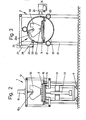
- the entire device has a deflection device 1, a rotating device 2 and a transport device 3.
- the deflection device 1 and the rotating device 2 are arranged in a sound-absorbing cabin 4, through which two roller conveyors 5 and 6 lead for transport pallets 9, which are operatively connected to each other at both ends of the cabin 4 by means of two lifting tables 7 and 8.
- the deflection device 1 has a frame 10 standing on vibration dampers 11, on which a clamping frame 12 is arranged so as to be vertically displaceable. At least one, preferably pneumatically operated, hammer 13 fastened in the frame 10 engages on a cross member 14 of the clamping frame 12 from below.
- the frame 10 can be swiveled or raised and lowered Transport rollers 15 are arranged, which form a roller plane with rollers 5a in their upper position and are thus part of the roller conveyor 5. By pivoting the transport rollers 15, the transport pallets 9 loaded with the casting 50 to be cored can be lowered onto the clamping frame 12.
- a clamping means 16 preferably a hydraulic cylinder, arranged on the clamping frame 12 on the side opposite the percussion hammer 13, presses a clamping element 16a against the cast part 50 after it has been actuated, as a result of which this, together with the transport pallet 9 resting on the cross member 14, in the clamping frame 12. is firmly clamped.
- the blows generated by the hammer 13 in rapid succession reach the casting 50 indirectly via the clamping frame 12 and the transport pallet 9, whereby the cores or the solid core sand in the casting 50 are loosened.
- FIG. 1 and 3 has a frame 20 on which circumferentially distributed rollers 21 are arranged, between which a frame 22 is rotatably mounted about a horizontal axis 23.
- This frame 22 is provided with transport rollers 25 which are part of the roller table 5 in a horizontal position defined by a locking device 24. In this position, the transport rollers 25 are operatively connected to a drive 31.
- a clamping device 26 is fastened to the frame 22 and has a clamping arm 26a which can be pressed against the cast part 50 by spring force. When the transport pallet 9 with the cast part 50 is moved in and out, the clamping arm 26a can be lifted off the cast part 50 against the spring force by means of an actuating device 27 fastened to the frame 20.
- the spring force is preferably generated by a torsion spring 28.
- the actuating device 27 is advantageously a pneumatically or hydraulically actuatable cylinder, the Piston rod 29 can be pressed against a lever 30 of the tensioning arm 26a and is brought into a fully retracted position during the rotation of the frame 22.
- a motor-driven roller 21 or another drive device By means of a motor-driven roller 21 or another drive device, the cast part 50 clamped in the frame 22 is rotated until the cavities of the cast part are free of the already loosened core sand.
- the first lifting table 7 also forms the loading station 17 for the transport pallets 9.
- Castings 50 supplied to the unpacking station are placed on the transport pallets 9 by means of a device (not shown), where they are held in a fixed position by means of parts 19 engaging in the castings 50.
- the castings 50 are cylinder blocks of engines, the parts designed as pins 19 coming to rest in the cylinder bores.
- the pins 19 can be inserted into the transport pallets 9 at different predetermined distances depending on the dimensions of the cylinder blocks to be cored.
- the loaded transport pallets 9 are brought by means of the lower roller table 5 through a closable cabin opening into the deflection station 1, in which the cores are broken or loosened by means of the blows of the impact hammer 13 acting indirectly on the cast part, as already described.
- the transport pallet 9 with the casting 50 is rolled into the rotating device 2, where, as already be wrote, the cavities of the casting are emptied by its rotation.
- the now completely cored casting 50 is now transported on the transport pallet 9 by means of the rollers 5a to an unloading station 18 which is designed as a lifting table 8.
- the casting 50 is lifted from the transport pallet 9 by means of devices (not shown) and fed to a further transport device.
- the empty transport pallet is raised by means of the lifting table 8 up to the height of the upper roller table 6 and transported through the cabin 4 to the first lifting table 7.
- the transport pallets are cleaned, for example by means of compressed air and / or brushes.
- the transport pallet rolled onto the lifting table 7 is then lowered to the height of the lower roller table 5 and can be loaded there with a further cast part.
- the entire cycle is carried out in cycles and automatically, a transport pallet 9 with cast part 50 being located in the deflection device 1 and in the rotating device 2 at the same time and at least four further transport pallets 9 in circulation according to FIG. 1.
Landscapes
- Engineering & Computer Science (AREA)
- Mechanical Engineering (AREA)
- Casting Devices For Molds (AREA)
- Molds, Cores, And Manufacturing Methods Thereof (AREA)
- Moulds For Moulding Plastics Or The Like (AREA)
- Braking Arrangements (AREA)
- Body Structure For Vehicles (AREA)
- Pens And Brushes (AREA)
Priority Applications (1)
| Application Number | Priority Date | Filing Date | Title |
|---|---|---|---|
| AT86102503T ATE33777T1 (de) | 1985-04-09 | 1986-02-26 | Einrichtung zum entkernen von gussteilen. |
Applications Claiming Priority (2)
| Application Number | Priority Date | Filing Date | Title |
|---|---|---|---|
| CH1506/85 | 1985-04-09 | ||
| CH1506/85A CH665975A5 (de) | 1985-04-09 | 1985-04-09 | Einrichtung zum entkernen von gussteilen. |
Publications (2)
| Publication Number | Publication Date |
|---|---|
| EP0200860A1 true EP0200860A1 (fr) | 1986-11-12 |
| EP0200860B1 EP0200860B1 (fr) | 1988-04-27 |
Family
ID=4212034
Family Applications (1)
| Application Number | Title | Priority Date | Filing Date |
|---|---|---|---|
| EP86102503A Expired EP0200860B1 (fr) | 1985-04-09 | 1986-02-26 | Dispositif pour débourrer des pièces coulées |
Country Status (7)
| Country | Link |
|---|---|
| US (1) | US4777689A (fr) |
| EP (1) | EP0200860B1 (fr) |
| CN (1) | CN1004613B (fr) |
| AT (1) | ATE33777T1 (fr) |
| CH (1) | CH665975A5 (fr) |
| DE (2) | DE3660148D1 (fr) |
| ES (1) | ES8701556A1 (fr) |
Cited By (6)
| Publication number | Priority date | Publication date | Assignee | Title |
|---|---|---|---|---|
| DE8800961U1 (de) * | 1988-01-27 | 1989-06-08 | "F. u. K." Frölich & Klüpfel Drucklufttechnik GmbH & Co KG, 5600 Wuppertal | Vorrichtung zum Entkernen von Gußstücken |
| DE8800960U1 (de) * | 1988-01-27 | 1989-06-08 | "F. u. K." Frölich & Klüpfel Drucklufttechnik GmbH & Co KG, 5600 Wuppertal | Vorrichtung zum Entkernen von Gußstücken |
| US5758713A (en) * | 1993-11-05 | 1998-06-02 | Dimafond - Distribution Et Ingenierie De Materiel Pour La Fonderie | Device for decoring cores of castings |
| EP0920975A3 (fr) * | 1997-12-08 | 1999-07-21 | Kvaerner U.S., Inc. | Dispositif de thermoformage avec recirculation linéaire des cadres support de feuille |
| AT15916U1 (de) * | 2017-02-24 | 2018-09-15 | Fill Gmbh | Vorrichtung zum Entkernen eines Werkstückes |
| CN112191825A (zh) * | 2020-09-23 | 2021-01-08 | 杨燕辉 | 一种用于电容器制造的具有保护结构的接线端子压铸设备 |
Families Citing this family (14)
| Publication number | Priority date | Publication date | Assignee | Title |
|---|---|---|---|---|
| US5054155A (en) * | 1990-02-16 | 1991-10-08 | Cmi International, Inc. | Apparatus for cleaning passageways in metal castings |
| DE10115098A1 (de) * | 2001-03-27 | 2002-10-02 | G & K Umformtechnik Gmbh | Vorrichtung zum Stanzen |
| FR2850305B1 (fr) * | 2003-01-23 | 2005-03-18 | Marcel Massin | Systeme automatise de debourrage et dispositif de debourrage |
| AU2003904221A0 (en) * | 2003-08-11 | 2003-08-21 | Castalloy Manufacturing Pty Ltd | Location of casting for post casting processes |
| US8186419B2 (en) * | 2008-07-08 | 2012-05-29 | GM Global Technology Operations LLC | Method and system for internal cleaning of complex castings |
| CN201744642U (zh) * | 2010-08-03 | 2011-02-16 | 青岛三锐机械制造有限公司 | 一种振击除芯机 |
| CN103230907A (zh) * | 2013-04-26 | 2013-08-07 | 湖北金仕伟智能装备技术有限公司 | 铸件内壁清理装置 |
| CN104057071B (zh) * | 2014-06-09 | 2016-01-27 | 无锡市蠡湖铸业有限公司 | 节能型涡壳落芯机 |
| FR3078276B1 (fr) * | 2018-02-23 | 2026-01-16 | Safran Aircraft Engines | Outillage de decochage d'une grappe de pieces de fonderie a cire perdue |
| CN110653342B (zh) * | 2019-10-17 | 2022-01-11 | 临沂茂源新材料科技有限公司 | 一种高压升温砂型铸造装置 |
| CN111822684B (zh) * | 2020-06-10 | 2021-08-13 | 安徽霍山龙鑫金属科技有限公司 | 铸造用脱模、清理机构 |
| CN111745613A (zh) * | 2020-07-02 | 2020-10-09 | 无锡韦恩科技有限公司 | 一种单元式幕墙板块翻转机构 |
| CN112008068B (zh) * | 2020-09-02 | 2021-09-07 | 天长市天翔集团有限公司 | 一种金属铸造脱模下料设备 |
| CN114888264B (zh) * | 2022-05-10 | 2023-07-11 | 保定恒生液力偶合器制造有限公司 | 一种制造偶合器用浇铸设备及生产工艺 |
Citations (5)
| Publication number | Priority date | Publication date | Assignee | Title |
|---|---|---|---|---|
| GB2063739A (en) * | 1979-11-28 | 1981-06-10 | Bayerische Motoren Werke Ag | A device for ejecting cores from castings |
| GB2067938A (en) * | 1980-01-17 | 1981-08-05 | Stoner & Saunders Andover Ltd | A casting-core knockout machine |
| DE3219390A1 (de) * | 1981-05-27 | 1982-12-16 | Werner Bazenheid Lüber | Vorrichtung zum entfernen des kernsandes aus guss-stuecken |
| DE3239262A1 (de) * | 1982-10-23 | 1984-04-26 | Alb. Klein Gmbh & Co Kg, 5241 Niederfischbach | Verfahren und vorrichtung zum entkernen von gussstuecken |
| DE3341894C1 (de) * | 1983-11-19 | 1985-03-14 | Bayerische Motoren Werke AG, 8000 München | Vorrichtung zum Entkernen von Gussstuecken durch Vibrationsschwingungen |
Family Cites Families (6)
| Publication number | Priority date | Publication date | Assignee | Title |
|---|---|---|---|---|
| US1570716A (en) * | 1923-04-11 | 1926-01-26 | John T Stoney | Cleaning apparatus |
| US1768428A (en) * | 1924-06-28 | 1930-06-24 | John T Stoney | Apparatus for cleaning castings |
| US2160581A (en) * | 1937-04-01 | 1939-05-30 | George W Behnke | Turn-over device |
| JPS5597863A (en) * | 1979-01-18 | 1980-07-25 | Mitsubishi Motors Corp | Sand stripping device of casting |
| JPS58148073A (ja) * | 1982-02-25 | 1983-09-03 | Toyota Motor Corp | 鋳造品の砂落し装置および砂落し方法 |
| JPS5927767A (ja) * | 1982-08-05 | 1984-02-14 | Daihatsu Motor Co Ltd | シリンダブロツク等鋳造物品の砂落し装置 |
-
1985
- 1985-04-09 CH CH1506/85A patent/CH665975A5/de not_active IP Right Cessation
-
1986
- 1986-02-26 EP EP86102503A patent/EP0200860B1/fr not_active Expired
- 1986-02-26 AT AT86102503T patent/ATE33777T1/de active
- 1986-02-26 DE DE8686102503T patent/DE3660148D1/de not_active Expired
- 1986-03-28 CN CN86102100.2A patent/CN1004613B/zh not_active Expired
- 1986-04-03 DE DE8608935U patent/DE8608935U1/de not_active Expired
- 1986-04-04 US US06/848,824 patent/US4777689A/en not_active Expired - Fee Related
- 1986-04-08 ES ES553770A patent/ES8701556A1/es not_active Expired
Patent Citations (5)
| Publication number | Priority date | Publication date | Assignee | Title |
|---|---|---|---|---|
| GB2063739A (en) * | 1979-11-28 | 1981-06-10 | Bayerische Motoren Werke Ag | A device for ejecting cores from castings |
| GB2067938A (en) * | 1980-01-17 | 1981-08-05 | Stoner & Saunders Andover Ltd | A casting-core knockout machine |
| DE3219390A1 (de) * | 1981-05-27 | 1982-12-16 | Werner Bazenheid Lüber | Vorrichtung zum entfernen des kernsandes aus guss-stuecken |
| DE3239262A1 (de) * | 1982-10-23 | 1984-04-26 | Alb. Klein Gmbh & Co Kg, 5241 Niederfischbach | Verfahren und vorrichtung zum entkernen von gussstuecken |
| DE3341894C1 (de) * | 1983-11-19 | 1985-03-14 | Bayerische Motoren Werke AG, 8000 München | Vorrichtung zum Entkernen von Gussstuecken durch Vibrationsschwingungen |
Non-Patent Citations (1)
| Title |
|---|
| PATENTS ABSTRACTS OF JAPAN, Band 7, Nr. 269 (M-259) [1414], 30. November 1983 & JP - A - 58 148 073 (TOYOTA JIDOSHA KOGYO K.K.) 03.09.1983 * |
Cited By (6)
| Publication number | Priority date | Publication date | Assignee | Title |
|---|---|---|---|---|
| DE8800961U1 (de) * | 1988-01-27 | 1989-06-08 | "F. u. K." Frölich & Klüpfel Drucklufttechnik GmbH & Co KG, 5600 Wuppertal | Vorrichtung zum Entkernen von Gußstücken |
| DE8800960U1 (de) * | 1988-01-27 | 1989-06-08 | "F. u. K." Frölich & Klüpfel Drucklufttechnik GmbH & Co KG, 5600 Wuppertal | Vorrichtung zum Entkernen von Gußstücken |
| US5758713A (en) * | 1993-11-05 | 1998-06-02 | Dimafond - Distribution Et Ingenierie De Materiel Pour La Fonderie | Device for decoring cores of castings |
| EP0920975A3 (fr) * | 1997-12-08 | 1999-07-21 | Kvaerner U.S., Inc. | Dispositif de thermoformage avec recirculation linéaire des cadres support de feuille |
| AT15916U1 (de) * | 2017-02-24 | 2018-09-15 | Fill Gmbh | Vorrichtung zum Entkernen eines Werkstückes |
| CN112191825A (zh) * | 2020-09-23 | 2021-01-08 | 杨燕辉 | 一种用于电容器制造的具有保护结构的接线端子压铸设备 |
Also Published As
| Publication number | Publication date |
|---|---|
| CN86102100A (zh) | 1986-10-08 |
| CH665975A5 (de) | 1988-06-30 |
| ES553770A0 (es) | 1986-12-01 |
| ATE33777T1 (de) | 1988-05-15 |
| DE8608935U1 (de) | 1986-07-03 |
| DE3660148D1 (en) | 1988-06-01 |
| US4777689A (en) | 1988-10-18 |
| CN1004613B (zh) | 1989-06-28 |
| ES8701556A1 (es) | 1986-12-01 |
| EP0200860B1 (fr) | 1988-04-27 |
Similar Documents
| Publication | Publication Date | Title |
|---|---|---|
| EP0200860B1 (fr) | Dispositif pour débourrer des pièces coulées | |
| DE3609086C2 (fr) | ||
| DE2610467C2 (fr) | ||
| DE102018107657A1 (de) | Vorrichtung zum Anziehen von Schraubverbindungen | |
| DE2629835A1 (de) | Werkzeugwechseleinrichtung fuer automatische werkzeugmaschinen | |
| DE69117277T2 (de) | Schleppfahrzeug für flugzeug | |
| DE2826519A1 (de) | Werkstueckaufnahmevorrichtung | |
| DE2618877C3 (de) | Vorrichtung zum Kontern und Brechen der Gewindeverbindungen zwischen Rohrkörpern | |
| EP0624456B1 (fr) | Dispositif de manipulation pour tringles de talon de pneu | |
| DE68923682T2 (de) | Klemmvorrichtung des Oberteils einer Metallform einer Reifenvulkanisiermaschine. | |
| EP1056556B1 (fr) | Dispositif de sertissage a elements de pression et de serrage | |
| EP0100944B1 (fr) | Dispositif d'alimentation dans une machine de traitement ou jet abrasif | |
| DE3003674C2 (de) | Vorrichtung zum Stoppen oder Wenden von Flaschenkästen | |
| DE4211773C2 (de) | Vorrichtung zum Heben und Senken von Lasten | |
| EP0887536A1 (fr) | Procédé pour l'inspection d'un palier et procédé pour le démontage d'une tige de piston d'un grand moteur diesel et outil et moteur pour l'exécution de ces procédés | |
| DE60001110T2 (de) | Vorrichtung zum entkernen von gussstücken | |
| DE2127012C3 (de) | Rohrbiegemaschine | |
| DE29703271U1 (de) | Bohrgerät zum Bohren von Löchern im Erdreich | |
| DE19517132C2 (de) | Verfahren und Vorrichtung zum Zusammenfügen beider Enden eines gürtelartigen Bauteils | |
| DE3518191A1 (de) | Entnahmevorrichtung | |
| DE19935902A1 (de) | Werkstück-Niederhaltevorrichtung | |
| DE3713008A1 (de) | Demontagehilfe | |
| DE29703272U1 (de) | Vorrichtung zur Handhabung von Bohrelementen | |
| AT263498B (de) | Montage- und Schweißeinrichtung | |
| DE2509292C3 (de) | Vorrichtung zum Ein- und Ausbauen von Pleueldeckeln |
Legal Events
| Date | Code | Title | Description |
|---|---|---|---|
| PUAI | Public reference made under article 153(3) epc to a published international application that has entered the european phase |
Free format text: ORIGINAL CODE: 0009012 |
|
| 17P | Request for examination filed |
Effective date: 19860226 |
|
| AK | Designated contracting states |
Kind code of ref document: A1 Designated state(s): AT DE FR GB IT NL SE |
|
| 17Q | First examination report despatched |
Effective date: 19870505 |
|
| GRAA | (expected) grant |
Free format text: ORIGINAL CODE: 0009210 |
|
| AK | Designated contracting states |
Kind code of ref document: B1 Designated state(s): AT DE FR GB IT NL SE |
|
| REF | Corresponds to: |
Ref document number: 33777 Country of ref document: AT Date of ref document: 19880515 Kind code of ref document: T |
|
| GBT | Gb: translation of ep patent filed (gb section 77(6)(a)/1977) | ||
| REF | Corresponds to: |
Ref document number: 3660148 Country of ref document: DE Date of ref document: 19880601 |
|
| ET | Fr: translation filed | ||
| ITF | It: translation for a ep patent filed | ||
| PLBE | No opposition filed within time limit |
Free format text: ORIGINAL CODE: 0009261 |
|
| STAA | Information on the status of an ep patent application or granted ep patent |
Free format text: STATUS: NO OPPOSITION FILED WITHIN TIME LIMIT |
|
| 26N | No opposition filed | ||
| PGFP | Annual fee paid to national office [announced via postgrant information from national office to epo] |
Ref country code: FR Payment date: 19910116 Year of fee payment: 6 |
|
| PGFP | Annual fee paid to national office [announced via postgrant information from national office to epo] |
Ref country code: GB Payment date: 19910117 Year of fee payment: 6 Ref country code: DE Payment date: 19910117 Year of fee payment: 6 |
|
| PGFP | Annual fee paid to national office [announced via postgrant information from national office to epo] |
Ref country code: AT Payment date: 19910124 Year of fee payment: 6 |
|
| PGFP | Annual fee paid to national office [announced via postgrant information from national office to epo] |
Ref country code: SE Payment date: 19910128 Year of fee payment: 6 |
|
| ITTA | It: last paid annual fee | ||
| PGFP | Annual fee paid to national office [announced via postgrant information from national office to epo] |
Ref country code: NL Payment date: 19910228 Year of fee payment: 6 |
|
| PG25 | Lapsed in a contracting state [announced via postgrant information from national office to epo] |
Ref country code: GB Effective date: 19920226 Ref country code: AT Effective date: 19920226 |
|
| PG25 | Lapsed in a contracting state [announced via postgrant information from national office to epo] |
Ref country code: SE Effective date: 19920227 |
|
| PG25 | Lapsed in a contracting state [announced via postgrant information from national office to epo] |
Ref country code: NL Effective date: 19920901 |
|
| NLV4 | Nl: lapsed or anulled due to non-payment of the annual fee | ||
| GBPC | Gb: european patent ceased through non-payment of renewal fee | ||
| PG25 | Lapsed in a contracting state [announced via postgrant information from national office to epo] |
Ref country code: FR Effective date: 19921030 |
|
| PG25 | Lapsed in a contracting state [announced via postgrant information from national office to epo] |
Ref country code: DE Effective date: 19921103 |
|
| REG | Reference to a national code |
Ref country code: FR Ref legal event code: ST |
|
| EUG | Se: european patent has lapsed |
Ref document number: 86102503.9 Effective date: 19920904 |
|
| PG25 | Lapsed in a contracting state [announced via postgrant information from national office to epo] |
Ref country code: IT Free format text: LAPSE BECAUSE OF NON-PAYMENT OF DUE FEES;WARNING: LAPSES OF ITALIAN PATENTS WITH EFFECTIVE DATE BEFORE 2007 MAY HAVE OCCURRED AT ANY TIME BEFORE 2007. THE CORRECT EFFECTIVE DATE MAY BE DIFFERENT FROM THE ONE RECORDED. Effective date: 20050226 |