EP0200875A2 - Procédé et dispositif pour la purification d'eau usée suivant la méthode de boues activées - Google Patents
Procédé et dispositif pour la purification d'eau usée suivant la méthode de boues activées Download PDFInfo
- Publication number
- EP0200875A2 EP0200875A2 EP86102914A EP86102914A EP0200875A2 EP 0200875 A2 EP0200875 A2 EP 0200875A2 EP 86102914 A EP86102914 A EP 86102914A EP 86102914 A EP86102914 A EP 86102914A EP 0200875 A2 EP0200875 A2 EP 0200875A2
- Authority
- EP
- European Patent Office
- Prior art keywords
- wastewater
- waste water
- oxygen
- pool
- sludge
- Prior art date
- Legal status (The legal status is an assumption and is not a legal conclusion. Google has not performed a legal analysis and makes no representation as to the accuracy of the status listed.)
- Granted
Links
Images


Classifications
-
- C—CHEMISTRY; METALLURGY
- C02—TREATMENT OF WATER, WASTE WATER, SEWAGE, OR SLUDGE
- C02F—TREATMENT OF WATER, WASTE WATER, SEWAGE, OR SLUDGE
- C02F3/00—Biological treatment of water, waste water, or sewage
- C02F3/02—Aerobic processes
- C02F3/12—Activated sludge processes
- C02F3/1236—Particular type of activated sludge installations
- C02F3/1263—Sequencing batch reactors [SBR]
-
- C—CHEMISTRY; METALLURGY
- C02—TREATMENT OF WATER, WASTE WATER, SEWAGE, OR SLUDGE
- C02F—TREATMENT OF WATER, WASTE WATER, SEWAGE, OR SLUDGE
- C02F3/00—Biological treatment of water, waste water, or sewage
- C02F3/006—Regulation methods for biological treatment
-
- C—CHEMISTRY; METALLURGY
- C02—TREATMENT OF WATER, WASTE WATER, SEWAGE, OR SLUDGE
- C02F—TREATMENT OF WATER, WASTE WATER, SEWAGE, OR SLUDGE
- C02F3/00—Biological treatment of water, waste water, or sewage
- C02F3/02—Aerobic processes
- C02F3/12—Activated sludge processes
-
- Y—GENERAL TAGGING OF NEW TECHNOLOGICAL DEVELOPMENTS; GENERAL TAGGING OF CROSS-SECTIONAL TECHNOLOGIES SPANNING OVER SEVERAL SECTIONS OF THE IPC; TECHNICAL SUBJECTS COVERED BY FORMER USPC CROSS-REFERENCE ART COLLECTIONS [XRACs] AND DIGESTS
- Y02—TECHNOLOGIES OR APPLICATIONS FOR MITIGATION OR ADAPTATION AGAINST CLIMATE CHANGE
- Y02W—CLIMATE CHANGE MITIGATION TECHNOLOGIES RELATED TO WASTEWATER TREATMENT OR WASTE MANAGEMENT
- Y02W10/00—Technologies for wastewater treatment
- Y02W10/10—Biological treatment of water, waste water, or sewage
-
- Y—GENERAL TAGGING OF NEW TECHNOLOGICAL DEVELOPMENTS; GENERAL TAGGING OF CROSS-SECTIONAL TECHNOLOGIES SPANNING OVER SEVERAL SECTIONS OF THE IPC; TECHNICAL SUBJECTS COVERED BY FORMER USPC CROSS-REFERENCE ART COLLECTIONS [XRACs] AND DIGESTS
- Y10—TECHNICAL SUBJECTS COVERED BY FORMER USPC
- Y10S—TECHNICAL SUBJECTS COVERED BY FORMER USPC CROSS-REFERENCE ART COLLECTIONS [XRACs] AND DIGESTS
- Y10S210/00—Liquid purification or separation
- Y10S210/902—Materials removed
- Y10S210/903—Nitrogenous
-
- Y—GENERAL TAGGING OF NEW TECHNOLOGICAL DEVELOPMENTS; GENERAL TAGGING OF CROSS-SECTIONAL TECHNOLOGIES SPANNING OVER SEVERAL SECTIONS OF THE IPC; TECHNICAL SUBJECTS COVERED BY FORMER USPC CROSS-REFERENCE ART COLLECTIONS [XRACs] AND DIGESTS
- Y10—TECHNICAL SUBJECTS COVERED BY FORMER USPC
- Y10S—TECHNICAL SUBJECTS COVERED BY FORMER USPC CROSS-REFERENCE ART COLLECTIONS [XRACs] AND DIGESTS
- Y10S210/00—Liquid purification or separation
- Y10S210/902—Materials removed
- Y10S210/906—Phosphorus containing
Definitions
- the invention relates to a method for wastewater treatment using the activated sludge process with an aerated activated sludge tank, from which treated wastewater runs off continuously.
- An additional problem of the wastewater treatment technology according to the activated sludge process is an uncontrolled formation of bulky sludge which is difficult to separate, especially in the case of unfavorable C: N: P ratios.
- a aerobic wastewater treatment process (AT-PS 321 833) is carried out in batches Treatment of the waste water under increased air pressure in the aeration tank with sudden pressure relief after the end of the biological treatment, whereby a certain sludge compaction is to be achieved.
- Van den Eynde and others (Europ. J. Appl. Microbiol. Biotechnol. 15 (1982) 246) was carried out in laboratory tests with mixed pure bacteria cultures by intermittent substrate feed to displace the filamentous bulky sludge bacteria by the desired flocculants. However, it is not easily possible to transfer laboratory results with pure cultures to technical wastewater treatment.
- the invention is based on the object of developing a method with which the tendency to form expanded sludge is suppressed even in the case of wastewater with unfavorable C: N: P ratios and furthermore achieves a constant cleaning performance within narrow limits regardless of daily and weekly fluctuations in the dirt load can be.
- the method according to the invention developed for this purpose is characterized in that the wastewater is supplied in batches by briefly releasing the wastewater inlet to the pool for the batchwise wastewater supply when the bacterial metabolic intensity in the pool drops below a predetermined value.
- the batchwise metering takes place in such a way that the wastewater inflow is interrupted for a certain time by a device with a valve function.
- the valve which can also be designed as an adjustable weir, is opened and within a short period of time a batch of fresh waste water reaches the activation tank.
- the next dosing cycle begins. Typical periods of the dosing cycle are e.g. 30-60 minutes.
- the average hydraulic load and the sludge return ratio are the same for batch dosing as for the usual continuous feeding of the aeration tank.
- the period of this in particular in the case of wastewater that tends to form a large amount of bulking sludge, is advantageous in a burst-wise or batch-wise manner to the aeration basin, but it must be adapted to the respective mining conditions.
- the 02 concentration is preferably measured continuously in the lower region of the activation tank using a suitable 0 2 electrode which is connected to a measuring amplifier.
- the measured value is preferably compared by means of a microprocessor with two adjustable setpoints, the second (lower) value being used to control the trouble-free operation of the system: at 0 2 concentrations below the first setpoint (e.g. 3-4 mg 0 2 / l) the inlet to the aeration tank is closed and in the sand trap or in the storage tank Wastewater dammed up. After the first 0 2 sol value has been exceeded, the inflow is preferably released via a timer, for example for 3 minutes (FIG. 4).
- the microprocessor switches to the second 0 2 setpoint (eg 0.5 mg / l). If this value does not fall below this second setpoint, for example 5 minutes after opening the inlet, there is either a breakdown fault or a dosing error, which triggers an alarm signal. For example, 15 minutes after the inlet has opened, the timer switches back to the first setpoint in the case of trouble-free operation, and the control loop is again in the initial state.
- stable drainage values can be achieved regardless of the incoming contaminant load and the temperature.
- the residual COD is somewhat lower in the process (5 - 10%) than with continuous loading of aeration tanks.
- a higher efficiency of the 0 2 entry is achieved during the phase of the reduced 0 2 concentrations below the second setpoint. This allows a certain reduction in the specific need for ventilation energy.
- a (lower) setpoint can also be used to trigger switching operations, e.g. at the end of the dosing process.
- any other hydrochemical or physico-chemical parameter (pH, rH, pC0 2 , concentrations of acetate, methanol or the like) can be used as a control variable which is maintained during of a dosing cycle changes sufficiently and in a characteristic manner.
- the cycle time or indicator values and the quantity supplied depend on the dirt load of the wastewater to be cleaned, the intended space or sludge load in the activated sludge tank and the desired cleaning result and can therefore be applied at very different values.
- the supply volume per cycle time is usually between 5 and 30%, in particular in the region of 10-20% of the aeration tank volume. But it can also e.g. in low-load operation (around 0.2 kg COD / kg dry substance. d) make up up to 50% and when treating heavily polluted industrial waste water in high-load operation (around 10 kg COD / kg TS. d) they are below 5%.
- the appropriate cycle time depends on the biological activity of the sludge and can be determined empirically. It will generally be in the 0.5-2 hour area for treating moderately contaminated wastewater requiring nitrification.
- the determination of the "switching values" for the wastewater supply (W 1 ) and the alarm triggering (W 2 ) are also determined empirically, with W 1, for example in the case of low-load operation and cleaning with nitrification, near the 0 2 saturation value of the curve (see FIG. 3) for the oxygen concentration in the aeration tank, ie in the range of 4 - is prepared 5 mg 0 2/1, while W 1 at high load operation and / or Vortheses concede at about 2 mg O 2 / l, or may even be provided below.
- W 1 can be in particular between 5% and 90%, in general between 50 and 80%.
- the alarm-triggering value of W 2 is also read from the continuous recording of the oxygen concentration: it lies above the (highest) oxygen minimum of the curve (see FIG. 3).
- W 2 is based in particular on the drop in the oxygen curve typical of the degradation process after the end of the wastewater supply: If the 02 measured value has not dropped below a predetermined value within a period of at most 10 min (in particular 2 - 5 min) as short as possible Alarm triggered. This predetermined value is clearly above the value typical for the selected alarm time, in particular 0.5 to 2 mg / l above.
- the dosing cycle can also be set using an electrical timer or a timer based on optimized empirical values. In this case the dosing cycle has a constant period length.
- the simplest arrangement for batchwise metering of the wastewater inflow into an aeration tank is to install an adjustable weir behind the sand trap, the function of which is regulated electromechanically (FIGS. 1 and 2).
- This device is particularly suitable for systems with largely uniform wastewater inflow (over 1).
- phase I of the dosing cycle the weir (2) stands vertically and blocks the wastewater flow from the (non-aerated or aerated) sand trap into the aeration tank.
- Phase II The locking mechanism of the adjustable weir is opened by an electrical pulse. It flips over and the accumulated wastewater flows into the aeration tank in a short time.
- Phase III The adjustable weir is brought back into a vertical position by means of a gear motor.
- an adjustable weir is served by an electromechanically operated slide that periodically controls the flow of sand trap via a trough or a pipe in accordance with the control signals of one of the control loops according to the invention opens and closes.
- the sludge is drawn off via 3.
- the tank content does not flow over an overflow edge into the collecting trough, but flows against resistance of sufficient size, e.g. through relatively narrow pipe sockets (clear width e.g. 3 - 4 cm) inserted into the basin wall in the form of a ring into the collecting trough and from here into the clarifier.
- the aeration tank B is thrust as fed with wastewater from the primary clarifier A via an element 2 with valve function, while the flow takes place continuously via a throttling point 4 into a secondary clarifier 5 with drain 6.
- the operation of the valve element 2 is subject to a control mechanism controlled by the probe 7, which is indicated by 8 and operates in the manner shown in FIG. 4.
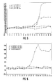
- the sludge volume index can be reduced to up to 400 ml g-1 (Fig. 5), but it does not achieve sufficient sedimentation behavior.
- the dosing cycles were set to 30-120 sec h 1 with a timer without changing the overall throughput compared to the continuous mode of operation maintained in a control basin.
- the batchwise metering of the wastewater which was not modified by nutrient additives resulted in a perfect settling behavior.
- the efficiency related to COD elimination (90 ⁇ 3%) did not deteriorate, but was even improved by about 5% on average of the measurements carried out so far.
Landscapes
- Life Sciences & Earth Sciences (AREA)
- Engineering & Computer Science (AREA)
- Biodiversity & Conservation Biology (AREA)
- Microbiology (AREA)
- Hydrology & Water Resources (AREA)
- Environmental & Geological Engineering (AREA)
- Water Supply & Treatment (AREA)
- Chemical & Material Sciences (AREA)
- Organic Chemistry (AREA)
- Molecular Biology (AREA)
- Health & Medical Sciences (AREA)
- Activated Sludge Processes (AREA)
- Water Treatment By Electricity Or Magnetism (AREA)
Priority Applications (1)
| Application Number | Priority Date | Filing Date | Title |
|---|---|---|---|
| AT86102914T ATE70251T1 (de) | 1985-03-07 | 1986-03-05 | Verfahren und vorrichtung zur abwasserreinigung nach dem belebtschlammverfahren. |
Applications Claiming Priority (2)
| Application Number | Priority Date | Filing Date | Title |
|---|---|---|---|
| DE3508126 | 1985-03-07 | ||
| DE19853508126 DE3508126A1 (de) | 1985-03-07 | 1985-03-07 | Verfahren und vorrichtung zur abwasserreinigung nach dem belebtschlammverfahren |
Publications (3)
| Publication Number | Publication Date |
|---|---|
| EP0200875A2 true EP0200875A2 (fr) | 1986-11-12 |
| EP0200875A3 EP0200875A3 (en) | 1988-08-31 |
| EP0200875B1 EP0200875B1 (fr) | 1991-12-11 |
Family
ID=6264500
Family Applications (1)
| Application Number | Title | Priority Date | Filing Date |
|---|---|---|---|
| EP19860102914 Expired - Lifetime EP0200875B1 (fr) | 1985-03-07 | 1986-03-05 | Procédé et dispositif pour la purification d'eau usée suivant la méthode de boues activées |
Country Status (5)
| Country | Link |
|---|---|
| US (1) | US4793930A (fr) |
| EP (1) | EP0200875B1 (fr) |
| JP (1) | JPS61242694A (fr) |
| AT (1) | ATE70251T1 (fr) |
| DE (2) | DE3508126A1 (fr) |
Cited By (3)
| Publication number | Priority date | Publication date | Assignee | Title |
|---|---|---|---|---|
| DE3710325A1 (de) * | 1987-03-28 | 1988-10-13 | Kernforschungsanlage Juelich | Abwasserreinigungsverfahren mit schubweiser abwasserzufuhr zum belebungsbecken |
| DE4116926A1 (de) * | 1990-05-31 | 1991-12-05 | Forschungszentrum Juelich Gmbh | Vorrichtung zur abwasserklaerung nach dem belebtschlammverfahren insbesondere mit denitrifizierung |
| CN119284995A (zh) * | 2024-08-27 | 2025-01-10 | 华能新华发电有限责任公司 | 一种工业废水处理系统 |
Families Citing this family (15)
| Publication number | Priority date | Publication date | Assignee | Title |
|---|---|---|---|---|
| DE3714370A1 (de) * | 1987-04-30 | 1988-11-10 | Hoechst Ag | Verfahren zur biologischen behandlung stickstoffbelasteter abwaesser |
| AT394033B (de) * | 1988-11-03 | 1992-01-27 | Voest Alpine Maschinenbau | Vorrichtung zum aufbereiten von fluessigkeiten |
| DK96989D0 (da) * | 1989-02-28 | 1989-02-28 | Faxe Kalkbrud Aktieselskabet | Fremgangsmaade til overvaagning af biologiske processer |
| DE3906943C2 (de) * | 1989-03-02 | 1994-03-03 | Biodetox Ges Zur Biolog Schads | Verfahren zur Abwasserreinigung und Belebtschlammanlage zur Durchführung des Verfahrens |
| DE3914357C2 (de) * | 1989-04-29 | 1997-07-17 | Gero Froese | Steuerungsanordnung und Verfahren zur Steuerung der mikrobiellen Behandlung von Abwässern |
| US5268094A (en) * | 1990-03-15 | 1993-12-07 | Long Jeffrey N | Wastewater processing apparatus |
| BE1006765A5 (fr) * | 1990-05-31 | 1994-12-06 | Forschungszentrum Juelich Gmbh | Dispositif pour l'epuration des eaux residuaires selon le procede a boue activee et, en particulier, avec denitrification. |
| DE4140915C2 (de) * | 1991-04-20 | 2000-06-08 | Intech Pev Informationstechnis | Kläranlage mit einstufigem Belebungsbecken und einem Reglersystem für die biochemischen Prozesse |
| DE4412890A1 (de) * | 1994-04-14 | 1995-10-19 | Herhof Umwelttechnik Gmbh | Verfahren und Vorrichtung zur Reinigung von Wasser, insbesondere aus einem Kompostierungsprozeß |
| DE4436739A1 (de) * | 1994-10-14 | 1996-04-18 | Peter Payer | Verfahren zum Reinigen von Abwasser |
| US5624563A (en) * | 1995-08-25 | 1997-04-29 | Hawkins; John C. | Process and apparatus for an activated sludge treatment of wastewater |
| US6106718A (en) * | 1998-07-01 | 2000-08-22 | Biochem Technology, Inc. | Enhanced denitrification process by monitoring and controlling carbonaceous nutrient addition |
| US6592757B2 (en) | 2000-02-01 | 2003-07-15 | O'brien & Gere Engineers, Inc. | Selector contact stabilization process and apparatus for wastewater treatment |
| US6383389B1 (en) * | 2001-02-15 | 2002-05-07 | United States Filter Corporation | Wastewater treatment system and method of control |
| KR102109144B1 (ko) * | 2017-09-29 | 2020-05-28 | 주식회사 아모센스 | 전원 제어 장치 및 방법 |
Family Cites Families (5)
| Publication number | Priority date | Publication date | Assignee | Title |
|---|---|---|---|---|
| DE1584923A1 (de) * | 1966-04-27 | 1969-11-27 | Koppers Gmbh Heinrich | Verfahren zur automatischen Regelung des Wasserstandes in Behandlungsbecken fuer diebiologische Reinigung von Abwaessern |
| AT321833B (de) * | 1971-06-14 | 1975-04-25 | Ludwig Csepai Dipl Ing Dr Tech | Verfahren zur biologischen Reinigung von Abwässern |
| DE2909333C2 (de) * | 1979-03-09 | 1985-10-17 | Linde Ag, 6200 Wiesbaden | Verfahren zur biologischen Reinigung von Abwasser |
| JPS55151262A (en) * | 1979-05-16 | 1980-11-25 | Hitachi Ltd | Measuring method for organism concentration |
| US4504393A (en) * | 1984-06-08 | 1985-03-12 | Chevron Research Company | Method and apparatus for controlling a rotating biological contactor |
-
1985
- 1985-03-07 DE DE19853508126 patent/DE3508126A1/de not_active Withdrawn
-
1986
- 1986-03-05 DE DE8686102914T patent/DE3682815D1/de not_active Expired - Lifetime
- 1986-03-05 EP EP19860102914 patent/EP0200875B1/fr not_active Expired - Lifetime
- 1986-03-05 AT AT86102914T patent/ATE70251T1/de not_active IP Right Cessation
- 1986-03-06 US US06/837,082 patent/US4793930A/en not_active Expired - Lifetime
- 1986-03-07 JP JP61048730A patent/JPS61242694A/ja active Pending
Cited By (5)
| Publication number | Priority date | Publication date | Assignee | Title |
|---|---|---|---|---|
| DE3710325A1 (de) * | 1987-03-28 | 1988-10-13 | Kernforschungsanlage Juelich | Abwasserreinigungsverfahren mit schubweiser abwasserzufuhr zum belebungsbecken |
| EP0284976A3 (en) * | 1987-03-28 | 1989-04-12 | Kernforschungsanlage Julich Gesellschaft Mit Beschrankter Haftung | Process for waste water purification with batch feed to the activated sludge tank |
| US5019266A (en) * | 1987-03-28 | 1991-05-28 | Forschungszentrum Juelich Gmbh | Waste water purification process with batchwise supply of waste water to the activated sludge tank |
| DE4116926A1 (de) * | 1990-05-31 | 1991-12-05 | Forschungszentrum Juelich Gmbh | Vorrichtung zur abwasserklaerung nach dem belebtschlammverfahren insbesondere mit denitrifizierung |
| CN119284995A (zh) * | 2024-08-27 | 2025-01-10 | 华能新华发电有限责任公司 | 一种工业废水处理系统 |
Also Published As
| Publication number | Publication date |
|---|---|
| ATE70251T1 (de) | 1991-12-15 |
| EP0200875A3 (en) | 1988-08-31 |
| DE3508126A1 (de) | 1986-09-11 |
| EP0200875B1 (fr) | 1991-12-11 |
| JPS61242694A (ja) | 1986-10-28 |
| US4793930A (en) | 1988-12-27 |
| DE3682815D1 (de) | 1992-01-23 |
Similar Documents
| Publication | Publication Date | Title |
|---|---|---|
| EP0200875B1 (fr) | Procédé et dispositif pour la purification d'eau usée suivant la méthode de boues activées | |
| DE69509329T2 (de) | Verfahren zur Steuerung der Belüftung eines Beckens für biologische Abwasseraufbereitung | |
| EP0284976B1 (fr) | Procédé pour la purification d'eau usée avec une alimentation de bassin à boues activées | |
| DE69101688T2 (de) | Verbesserter Reaktor für biologische Behandlung von Abwasser. | |
| DE2532199A1 (de) | Verfahren zur ueberwachung und regelung der biologischen aktivitaet der mikroorganismen in einer biologischen abwasserreinigungsanlage | |
| DE3241348C2 (fr) | ||
| DE10352636A1 (de) | Verfahren und Anlage zur Aufbereitung von Abwässern auf Schiffen | |
| EP1854766A1 (fr) | Procédé et dispositif destinés au traitement d'eaux usées | |
| DE1904206A1 (de) | Anlage zur Abwasserreinigung durch Flockung und Belebung | |
| EP0851844A1 (fr) | Procede d'epuration des eaux usees | |
| EP0773908B1 (fr) | Procede et dispositif permettant d'epurer des eaux usees, notamment pour des installations domestiques entierement biologiques d'epuration des eaux residuaires | |
| EP0834475B1 (fr) | Procédé et installation pour la dégradation des contaminants organiques dans les eaux usées | |
| EP0339013A2 (fr) | Appareil de traitement d'eau usée | |
| DE1642411A1 (de) | Verfahren zur Reinigung der Schmutzfluessigkeit von Wasserklosetts und anderen sanitaeren Installationen | |
| DE10127554B4 (de) | Verfahren zur biologischen Reinigung von Abwässern | |
| EP3310720B1 (fr) | Procédé aérobie de traitement d'un flux d'eaux résiduaires biodégradables | |
| DE3129926A1 (de) | Vorrichtung zur biologischen reinigung organischer abwaesser | |
| EP0338182A1 (fr) | Appareil pour le traitement d'eau usée | |
| EP0534351A2 (fr) | Procédé et installation pour le traitement d'eau usée ammonicale à haute concentration | |
| AT352032B (de) | Biologische hausklaeranlage mit belueftetem belebungsbecken und nachgeschaltetem klaer- becken | |
| DE3226797A1 (de) | Anlage zur aufzucht von nutzbaren fischen | |
| DE10123152A1 (de) | Biologische Kläranlage für kommunale, gewerbliche und landwirtschaftliche Abwässer und Verfahren zum Betreiben der Anlage | |
| DE4311934C2 (de) | Verfahren und Vorrichtung zur Reinigung von Rohabwasser mit Nährstoffelimination | |
| DE3637476A1 (de) | Verfahren zur biologischen reinigung von abwasser | |
| DE10244323B4 (de) | Vorrichtung für die Behandlung von fetthaltigem Abwasser vor dessen Einleitung in das Abwasserleitungsnetz |
Legal Events
| Date | Code | Title | Description |
|---|---|---|---|
| PUAI | Public reference made under article 153(3) epc to a published international application that has entered the european phase |
Free format text: ORIGINAL CODE: 0009012 |
|
| AK | Designated contracting states |
Kind code of ref document: A2 Designated state(s): AT BE CH DE FR GB IT LI LU NL SE |
|
| XX | Miscellaneous (additional remarks) |
Free format text: EIN ANTRAG NACH REGEL 88 EPUE AUF BERICHTIGUNG DER FIFUR 4 LIEGT VOR. HIERUEBER WIR VON DER PRUEFUNGSABTEILUNG ENTSCHIEDUNG WERDEN (RICHTLINIEN FUER DIE PRUEFUNG IM EPA, A V 2.2). |
|
| PUAL | Search report despatched |
Free format text: ORIGINAL CODE: 0009013 |
|
| AK | Designated contracting states |
Kind code of ref document: A3 Designated state(s): AT BE CH DE FR GB IT LI LU NL SE |
|
| 17P | Request for examination filed |
Effective date: 19890224 |
|
| RAP3 | Party data changed (applicant data changed or rights of an application transferred) |
Owner name: FORSCHUNGSZENTRUM JUELICH GMBH |
|
| 17Q | First examination report despatched |
Effective date: 19900320 |
|
| GRAA | (expected) grant |
Free format text: ORIGINAL CODE: 0009210 |
|
| DX | Miscellaneous (deleted) | ||
| AK | Designated contracting states |
Kind code of ref document: B1 Designated state(s): AT BE CH DE FR GB IT LI LU NL SE |
|
| REF | Corresponds to: |
Ref document number: 70251 Country of ref document: AT Date of ref document: 19911215 Kind code of ref document: T |
|
| REF | Corresponds to: |
Ref document number: 3682815 Country of ref document: DE Date of ref document: 19920123 |
|
| ET | Fr: translation filed | ||
| GBT | Gb: translation of ep patent filed (gb section 77(6)(a)/1977) | ||
| ITF | It: translation for a ep patent filed | ||
| PLBE | No opposition filed within time limit |
Free format text: ORIGINAL CODE: 0009261 |
|
| STAA | Information on the status of an ep patent application or granted ep patent |
Free format text: STATUS: NO OPPOSITION FILED WITHIN TIME LIMIT |
|
| 26N | No opposition filed | ||
| PGFP | Annual fee paid to national office [announced via postgrant information from national office to epo] |
Ref country code: GB Payment date: 19940217 Year of fee payment: 9 |
|
| PGFP | Annual fee paid to national office [announced via postgrant information from national office to epo] |
Ref country code: SE Payment date: 19940329 Year of fee payment: 9 |
|
| PGFP | Annual fee paid to national office [announced via postgrant information from national office to epo] |
Ref country code: LU Payment date: 19940331 Year of fee payment: 9 |
|
| PGFP | Annual fee paid to national office [announced via postgrant information from national office to epo] |
Ref country code: CH Payment date: 19940420 Year of fee payment: 9 |
|
| EPTA | Lu: last paid annual fee | ||
| EAL | Se: european patent in force in sweden |
Ref document number: 86102914.8 |
|
| PG25 | Lapsed in a contracting state [announced via postgrant information from national office to epo] |
Ref country code: LU Free format text: LAPSE BECAUSE OF NON-PAYMENT OF DUE FEES Effective date: 19950305 Ref country code: GB Effective date: 19950305 |
|
| PG25 | Lapsed in a contracting state [announced via postgrant information from national office to epo] |
Ref country code: SE Effective date: 19950306 |
|
| PG25 | Lapsed in a contracting state [announced via postgrant information from national office to epo] |
Ref country code: LI Effective date: 19950331 Ref country code: CH Effective date: 19950331 |
|
| GBPC | Gb: european patent ceased through non-payment of renewal fee |
Effective date: 19950305 |
|
| REG | Reference to a national code |
Ref country code: CH Ref legal event code: PL |
|
| EUG | Se: european patent has lapsed |
Ref document number: 86102914.8 |
|
| PGFP | Annual fee paid to national office [announced via postgrant information from national office to epo] |
Ref country code: NL Payment date: 20030317 Year of fee payment: 18 |
|
| PGFP | Annual fee paid to national office [announced via postgrant information from national office to epo] |
Ref country code: FR Payment date: 20030318 Year of fee payment: 18 |
|
| PGFP | Annual fee paid to national office [announced via postgrant information from national office to epo] |
Ref country code: AT Payment date: 20030321 Year of fee payment: 18 |
|
| PGFP | Annual fee paid to national office [announced via postgrant information from national office to epo] |
Ref country code: BE Payment date: 20030326 Year of fee payment: 18 |
|
| PG25 | Lapsed in a contracting state [announced via postgrant information from national office to epo] |
Ref country code: AT Free format text: LAPSE BECAUSE OF NON-PAYMENT OF DUE FEES Effective date: 20040305 |
|
| PG25 | Lapsed in a contracting state [announced via postgrant information from national office to epo] |
Ref country code: BE Free format text: LAPSE BECAUSE OF NON-PAYMENT OF DUE FEES Effective date: 20040331 |
|
| BERE | Be: lapsed |
Owner name: *FORSCHUNGSZENTRUM JUELICH G.M.B.H. Effective date: 20040331 |
|
| PG25 | Lapsed in a contracting state [announced via postgrant information from national office to epo] |
Ref country code: NL Free format text: LAPSE BECAUSE OF NON-PAYMENT OF DUE FEES Effective date: 20041001 |
|
| PG25 | Lapsed in a contracting state [announced via postgrant information from national office to epo] |
Ref country code: FR Free format text: LAPSE BECAUSE OF NON-PAYMENT OF DUE FEES Effective date: 20041130 |
|
| NLV4 | Nl: lapsed or anulled due to non-payment of the annual fee |
Effective date: 20041001 |
|
| REG | Reference to a national code |
Ref country code: FR Ref legal event code: ST |
|
| PG25 | Lapsed in a contracting state [announced via postgrant information from national office to epo] |
Ref country code: IT Free format text: LAPSE BECAUSE OF NON-PAYMENT OF DUE FEES;WARNING: LAPSES OF ITALIAN PATENTS WITH EFFECTIVE DATE BEFORE 2007 MAY HAVE OCCURRED AT ANY TIME BEFORE 2007. THE CORRECT EFFECTIVE DATE MAY BE DIFFERENT FROM THE ONE RECORDED. Effective date: 20050305 |
|
| PGFP | Annual fee paid to national office [announced via postgrant information from national office to epo] |
Ref country code: DE Payment date: 20050309 Year of fee payment: 20 |