EP0200920A2 - Domestic electric range - Google Patents
Domestic electric range Download PDFInfo
- Publication number
- EP0200920A2 EP0200920A2 EP86104531A EP86104531A EP0200920A2 EP 0200920 A2 EP0200920 A2 EP 0200920A2 EP 86104531 A EP86104531 A EP 86104531A EP 86104531 A EP86104531 A EP 86104531A EP 0200920 A2 EP0200920 A2 EP 0200920A2
- Authority
- EP
- European Patent Office
- Prior art keywords
- switch
- door
- oven
- operating position
- grill
- Prior art date
- Legal status (The legal status is an assumption and is not a legal conclusion. Google has not performed a legal analysis and makes no representation as to the accuracy of the status listed.)
- Granted
Links
Images
Classifications
-
- F—MECHANICAL ENGINEERING; LIGHTING; HEATING; WEAPONS; BLASTING
- F24—HEATING; RANGES; VENTILATING
- F24C—DOMESTIC STOVES OR RANGES ; DETAILS OF DOMESTIC STOVES OR RANGES, OF GENERAL APPLICATION
- F24C7/00—Stoves or ranges heated by electric energy
- F24C7/08—Arrangement or mounting of control or safety devices
- F24C7/087—Arrangement or mounting of control or safety devices of electric circuits regulating heat
-
- F—MECHANICAL ENGINEERING; LIGHTING; HEATING; WEAPONS; BLASTING
- F24—HEATING; RANGES; VENTILATING
- F24C—DOMESTIC STOVES OR RANGES ; DETAILS OF DOMESTIC STOVES OR RANGES, OF GENERAL APPLICATION
- F24C15/00—Details
- F24C15/02—Doors specially adapted for stoves or ranges
Definitions
- the invention relates to household electric ovens comprising a cooking chamber which opens on its front face and which contains a heating element for the vault and at least one heating element for silk.
- the invention relates, more specifically, household ovens of this kind which further comprise a switch capable of occupying either an "oven operating" position for which at least the hearth resistance is supplied, or an "operating position in grill “for which only the vault resistance is supplied, while a door arranged on said front face is adapted to take, in particular, either a closed position or” oven operation "for which it is applied against the surrounding the front opening, either a half-open or "grill operation” position for which it leaves on this opening an air circulation space between the enclosure and the outside.
- the invention aims to eliminate these drawbacks.
- An oven according to the invention comprises movement transmission members arranged between the resistance control switch and the door and capable of ensuring that the passage of this switch from its operating position in the oven to its operating position in the grill automatically the passage of the door from its closed position to its ajar position.
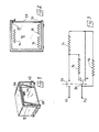
- the oven shown comprises a cooking chamber 12 which opens on its front face and which contains a heating resistance of the roof 14 and two heating elements of the bottom 16 and 18. These resistances are controlled by a switch 20 (FIGS. 3 to 5) which is likely to occupy either an operating position in the oven ( Figure 4 and position A in Figure 3), or an operating position in the grill ( Figure 5 and position B in Figure 3).
- a switch 20 FIGGS. 3 to 5
- the resistor 16, on the one hand, and all of the resistors 14 and 18 in series, on the other hand are supplied in parallel on the mains voltage applied to the input terminals 22 and 24.
- For the grill operating position only the top heater 14 is supplied.
- the supply voltage is applied to the resistors through a thermostatic switch 26 (only a small part of which is shown in FIGS. 4 and 5) intended to regulating the temperature of the cooking chamber during operation in the oven.
- the cooking chamber 12 is equipped with a door 28 arranged on the front face and articulated around a horizontal axis 30 located in the vicinity of its lower edge.
- This door can take, in particular, either a closed position ( Figures 2 and 4) for which it is applied against the surround 32 of the front opening, or a half-open position ( Figures 1 and 5) for which it leaves on this opening an air circulation space 34 between the enclosure 12 and the outside.
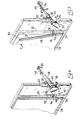
- the resistance control switch 20 is actuated by a movable key 36. This key is itself operated by a rotary shaft 38 which is itself coupled to the regulating switch 40 of the thermostatic switch 26.
- the shaft 38 is provided with a manipulation button 42 and carries a lateral projection 44 which, for a determined angular position of this shaft - (fig.5), comes to operate the key 36 of the switch 20 to bring this switch into its grill operating position (position B of the figure 3).
- This position corresponds to an angular position of the button 42 identified by the letter G, as can be seen in FIG. 5, on which a partial cutout of the shaft 38 has been carried out in order to clearly show the projection 44.
- the adjustment shaft 40 ensures, for this position, a blocking of the thermostatic switch 26 in a permanently closed position of this switch.
- the projection 44 releases the key 36 and thus leaves the switch 20 in its operating position in the oven (position A in FIG. 3), the thermostatic switch. 26 being itself also released to ensure temperature regulation as a function of the chosen setting: this choice is made by turning the button 42 to place it in correspondence with one or the other of numerical marks (for example 10 or 9, as in Figures 4 and 5).
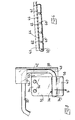
- These movement transmission members comprise a stay 46 mounted movably on the surround 32 of the front opening and mechanically linked to the control shaft 38 of the switch 20 so that, when this switch is in its operating position in oven ( Figure 4), the stay 46 is in a rest position, for which it is retracted to let the door 28 come to its closed position, and that, when this switch switches to its operating position on the grill ( Figure 5 ), the landlord 46 goes into an active position for which he is interposed between the surround 32 and the lateral edge 48 of the door 28 to cause this door to pivot outwards to its ajar position and to keep it in this position.
- the spacing 46 is constituted by a sliding rack whose teeth 50 are engaged with a toothed wheel 52 secured to the rotary shaft 38 and whose a free end pointed carries a inclined ramp 54 adapted to engage between the edge 48 of the door 28 and the surround 32 when the rack passes into its active position.
- the transmission members arranged between the switch 20 and the door 28, and constituted by the shaft 38, the toothed wheel 52, the rack 46, and the ramp 54, are adapted to ensure, not only that the passage of the switch 20 in its operating position in the grill causes the door to pass into its ajar position, but also, conversely, that the return of the door to its closed position causes the switch 20 to pass into its operating position in the oven.
Landscapes
- Engineering & Computer Science (AREA)
- Chemical & Material Sciences (AREA)
- Combustion & Propulsion (AREA)
- Mechanical Engineering (AREA)
- General Engineering & Computer Science (AREA)
- Electric Stoves And Ranges (AREA)
- Cookers (AREA)
- Insulated Conductors (AREA)
- Organic Insulating Materials (AREA)
- Carbon And Carbon Compounds (AREA)
- Physical Water Treatments (AREA)
- Iron Core Of Rotating Electric Machines (AREA)
- Reciprocating, Oscillating Or Vibrating Motors (AREA)
- Vending Machines For Individual Products (AREA)
- Switches With Compound Operations (AREA)
- Glass Compositions (AREA)
- Inorganic Insulating Materials (AREA)
Abstract
Ce four comprend une enceinte de cuisson chauffée par des résistances de voûte et de sole, un commutateur de commande des résistances pouvant occuper, soit une position "four", soit une position "gril" pour laquelle seule la résistance de voûte est alimentée, et une porte adaptée à prendre, en particulier, une position entrouverte permettant une circulation d'air. Selon l'invention, ce four comprend des organes de transmission de mouvement (38, 52, 46, 54) agencés entre le commutateur (20) et la porte (28) et propres à assurer que le passage du commutateur à sa position "gril" entraîne automatiquement le passage de la porte (28) de sa position fermée à sa position entrouverte.This oven comprises a cooking chamber heated by top and bottom resistances, a resistance control switch which can occupy either an "oven" position or a "grill" position for which only the top resistance is supplied, and a door adapted to take, in particular, a half-open position allowing air circulation. According to the invention, this oven comprises movement transmission members (38, 52, 46, 54) arranged between the switch (20) and the door (28) and suitable for ensuring that the passage of the switch to its "grill" position "automatically causes the door (28) to pass from its closed position to its ajar position.
Description
L'invention se rapporte aux fours ménagers électriques comprenant une enceinte de cuisson qui s'ouvre sur sa face frontale et qui contient une résistance chauffante de voûte et au moins une résistance chauffante de soie.The invention relates to household electric ovens comprising a cooking chamber which opens on its front face and which contains a heating element for the vault and at least one heating element for silk.
L'invention concerne, plus précisément, les fours ménagers de ce genre qui comprennent en outre un commutateur susceptible d'occuper soit une position "de fonctionnement en four" pour laquelle au moins la résistance de sole est alimentée, soit une position "de fonctionnement en gril" pour laquelle seule la résistance de voûte est alimentée, tandis qu'une porte agencée sur ladite face frontale est adaptée à prendre, en particulier, soit une position fermée ou "de fontionnement en four" pour laquelle elle est appliquée contre l'entourage de l'ouverture frontale, soit une position entrouverte ou "de fonctionnement en gril" pour laquelle elle laisse sur cette ouverture un espace de circulation d'air entre l'enceinte et l'extérieur.The invention relates, more specifically, household ovens of this kind which further comprise a switch capable of occupying either an "oven operating" position for which at least the hearth resistance is supplied, or an "operating position in grill "for which only the vault resistance is supplied, while a door arranged on said front face is adapted to take, in particular, either a closed position or" oven operation "for which it is applied against the surrounding the front opening, either a half-open or "grill operation" position for which it leaves on this opening an air circulation space between the enclosure and the outside.
Avec les appareils connus de ce genre, il arrive que l'usager, lors du fonctionnement en gril, omette de placer la porte en position entrouverte, ce qui, non seulement nuit à la qualité de l'opération de grillage qui ne peut être normalement menée à bien qu'avec une ventilation suffisante de l'aliment à griller, mais encore risque de provoquer, soit une élévation anormale de la température dans l'enceinte de cuisson du fait que la résistance de voûte est de puissance généralement élevée, soit une interruption de toute alimentation électrique à la suite de l'intervention d'un thermostat équipant l'appareil.With the known devices of this kind, it happens that the user, during the operation in grill, omits to place the door in half-opened position, which, not only harms the quality of the operation of toasting which cannot be normally carried out with sufficient ventilation of the food to be grilled, but still risks causing either an abnormal rise in temperature in the cooking chamber since the vault resistance is generally of high power, or a interruption of all power supply following the intervention of a thermostat fitted to the device.
L'invention a pour but de supprimer ces inconvénients.The invention aims to eliminate these drawbacks.
Un four selon l'invention comporte des organes de transmission de mouvement agencés entre le commutateur de commande des résistances et la porte et propres à assurer que le passage de ce commutateur de sa position de fonctionnement en four à sa position de fonctionnement en gril entraîne automatiquement le passage de la porte de sa position fermée à sa position entrouverte.An oven according to the invention comprises movement transmission members arranged between the resistance control switch and the door and capable of ensuring that the passage of this switch from its operating position in the oven to its operating position in the grill automatically the passage of the door from its closed position to its ajar position.
Ainsi l'usager n'a plus à se préoccuper lui-même de placer la porte en position convenable pour le fonctionnement en gril.So the user no longer has to worry about placing the door in a suitable position for grill operation.
Les caractéristiques et avantages de l'invention ressortiront d'ailleurs de la description qui va suivre, à titre d'exemple, en référence aux dessins annexés, dans lesquels :
- la figure 1 représente en perspective un four ménager électrique auquel est appliquée l'invention ; la figure 2 représente schématiquement ce four en coupe transversale verticale ; la figure 3 est un - schéma électrique du circuit d'alimentation des résistances chauffantes ; la figure 4 représente en en perspective, à grande échelle, les organes de transmission de mouvement agencés entre le commutateur de commande des résistances et la porte, pour la position de fonctionnement en four ; la figure 5 est une vue analogue des mêmes organes pour la position de fonctionnement en gril.
- Figure 1 shows in perspective an electric household oven to which the invention is applied; Figure 2 schematically shows this oven in vertical cross section; FIG. 3 is an electrical diagram of the supply circuit for the heating resistors; FIG. 4 shows in perspective, on a large scale, the movement transmission members arranged between the resistance control switch and the door, for the operating position in the oven; Figure 5 is a similar view of the same members for the grill operating position.
Le four représenté comprend une enceinte de cuisson 12 qui s'ouvre sur sa face frontale et qui contient une résistance chauffante de voûte 14 et deux résistances chauffantes de sole 16 et 18. Ces résistances sont commandées par un commutateur 20 (figures 3 à 5) qui est susceptible d'occuper, soit une position de fonctionnement en four (figure 4 et position A de la figure 3), soit une position de fonctionnement en gril (figure 5 et position B de la figure 3). Pour la position de fonctionnement en four, la résistance 16, d'une part, et l'ensemble des résistances 14 et 18 en série, d'autre part, sont alimentés en parallèle sur la tension du secteur appliquée aux bornes d'entrée 22 et 24. Pour la position de fonctionnement en gril, seule la résistance de voûte 14 est alimentée. Aussi bien en la position de fonctionnement en four qu'en la position de fonctionnement en gril, la tension d'alimentation est appliquée aux résistances à travers un interrupteur thermostatique 26 (dont une petite partie seulement est représentée aux figures 4 et 5) destiné à la régulation de la température de l'enceinte de cuisson lors du fonctionnement en four.The oven shown comprises a
L'enceinte du cuisson 12 est équipée d'une porte 28 agencée sur la face frontale et articulée autour d'un axe horizontal 30 situé au voisinage de son bord inférieur. Cette porte peut prendre, en particulier, soit une position fermée (figures 2 et 4) pour laquelle elle est appliquée contre l'entourage 32 de l'ouverture frontale, soit une position entrouverte (figures 1 et 5) pour laquelle elle laisse sur cette ouverture un espace 34 de circulation d'air entre l'enceinte 12 et l'extérieur.The
Le commutateur 20 de commande des résistances est actionné par une touche mobile 36. Cette touche est elle-même manoeuvrée par un arbre rotatif 38 qui est lui-même accouplé à rarbre de réglage 40 de l'interrupteur thermostatique 26.The
L'arbre 38 est muni d'un bouton de manipulation 42 et porte une saillie latérale 44 qui, pour une position angulaire déterminée de cet arbre - (fig.5), vient manoeuvrer la touche 36 du commutateur 20 pour amener ce commutateur en sa position de fonctionnement en gril (position B de la figure 3). Cette position correspond à une position angulaire du bouton 42 repérée par la lettre G, comme on le voit bien sur la figure 5, sur laquelle on a effectué un arrachement partiel de l'arbre 38 pour bien laisser voir la saillie 44. On notera qu'en même temps, l'arbre de réglage 40 assure, pour cette position, un blocage de l'interrupteur thermostatique 26 en une position de fermeture permanente de cet interrupteur.The
Pour toute position angulaire de réglage autre que ladite position déterminée repérée par la lettre G, la saillie 44 libère la touche 36 et laisse ainsi le commutateur 20 en sa position de fonctionnement en four (position A de la figure 3), l'interrupteur thermostatique 26 étant lui-même également libéré pour assurer la régulation de température en fonction du réglage choisi : ce choix s'effectue en faisant tourner le bouton 42 pour le placer en correspondance de l'un ou l'autre de repères chiffrés (par exemple 10 ou 9, tels que sur les figures 4 et 5).For any angular position of adjustment other than said determined position identified by the letter G, the
Des organes de transmission de mouvement, agencés entre le commutateur 20 et la porte 28, sont adaptés à assurer que le passage de ce commutateur de sa position de fonctionnement en four à sa position de fonctionnement en gril entraîne automatiquement le passage de la porte 28 de sa position fermée (figure 4) à sa position entrouverte (figure 5).Motion transmission members, arranged between the
Ces organes de transmission de mouvement comprennent un entrebâilleur 46 monté mobile sur l'entourage 32 de l'ouverture frontale et lié mécaniquement à l'arbre de commande 38 du commutateur 20 de telle manière que, lorsque ce commutateur est en sa position de fonctionnement en four (figure 4), l'entrebâilleur 46 est en une position de repos, pour laquelle il est escamoté pour laisser la porte 28 venir en sa position fermée, et que, lorsque ce commutateur passe à sa position de fonctionnement en gril (figure 5), l'entre- bailleur 46 passe en une position active pour laquelle il s'interpose entre l'entourage 32 et le bord latéral 48 de la porte 28 pour amener cette porte à pivoter vers l'extérieur jusqua'à sa position entrouverte et pour la maintenir en cette position.These movement transmission members comprise a
L'entrebali leur 46, comme on le voit sur les figures 4 et 5, est constitué par une crémaillère coulissante dont la denture 50 est en prise avec une roue dentée 52 solidaire de l'arbre rotatif 38 et dont une extrémité libre pointue porte une rampe inclinée 54 adaptée à s'engager entre le bord 48 de la porte 28 et l'entourage 32 lorsque la crémaillère passe en sa position active.The
Si l'usager, alors que le commutateur 20 est en sa position de fonctionnement en gril (figure 5), exerce sur la porte 28 une poussée (fléche F) tendant à la faire passer de sa position entrouverte à sa position fermée, le bord 48 de cette porte coopère avec la rampe inclinée 54 pour ramener la crémaillère 46 à sa position de repos (fléche H) et entraîner ainsi une rotation de l'arbre 38 (fléche J) propre à faire passer le commutateur 20 de sa position de fonctionnement en gril à sa position de fonctionnement en four(repère 10).If the user, while the
Ainsi, les organes de transmission agencés entre le commutateur 20 et la porte 28, et constitués par l'arbre 38, la roue dentée 52, la crémaillère 46, et la rampe 54, sont adaptés à assurer, non seulement que le passage du commutateur 20 à sa position de fonctionnement en gril entraîne le passage de la porte en sa position entrouverte, mais encore, inversement, que le retour de la porte vers sa position fermée entraîne le passage du commutateur 20 en sa position de fonctionnement en four.Thus, the transmission members arranged between the
L'usager n'a donc pas à se préoccuper de placer la porte 28 en position convenable pour le fonctionnement en gril, puisque cette opération se fait automatiquement. Il n'a pas non plus à se préoccuper de manipuler le bouton 42 lorsqu'il souhaite revenir à la position de fonctionnement en four, puisque cette opération s'effectue, elle aussi, automatiquement.The user therefore does not have to worry about placing the
Claims (6)
caractériséen ce que les organes de transmission de mouvement comprennent un entrebâilleur (46) monté mobile sur l'entourage (32) de l'ouverture frontale et lié mécaniquement à la commande du commutateur (20) de telle manière que, lorsque le commutateur (20) est en sa position de fonctionnement en four, l'entrebâilleur (46) est en une position de repos pour laquelle il est escamoté et laisse ainsi la porte (28) venir en sa position fermée, et que, lorsque le commutateur (20) passe à sa position de fonctionnement en gril, l'entrebâilleur (46) passe en une position active pour laquelle il s'interpose entre la porte (28) et ledit entourage (32) pour amener et maintenir cette porte en sa position entrouverte.2. Household oven according to claim 1,
characterized in that the movement transmitting members comprise a spacer (46) movably mounted on the surround (32) of the front opening and mechanically linked to the control of the switch (20) so that when the switch (20 ) is in its operating position in the oven, the stay (46) is in a rest position for which it is retracted and thus lets the door (28) come into its closed position, and that, when the switch (20) passes to its operating position in the grill, the stay-open device (46) passes to an active position for which it is interposed between the door (28) and said surround (32) to bring and maintain this door in its ajar position.
caractériséen ce que, le commutateur (20) étant commandé par un arbre rotatif (38), l'entrebâilleur - (46) est constitué par une crémaillère coulissante dont la denture (50) est en prise avec une roue dentée (52) solidaire dudit arbre rotatif (38), et dont une extrémité libre porte une rampe inclinée (54) adaptée à s'engager entre un bord (48) de la porte (28) et l'entourage (32) lorsque la crémaillère (46) passe en sa position active.3. Household oven according to claim 2,
characterized in that, the switch (20) being controlled by a rotary shaft (38), the spacer - (46) is constituted by a sliding rack whose teeth (50) are engaged with a toothed wheel (52) integral with said rotary shaft (38), and a free end of which carries an inclined ramp (54) adapted to engage between an edge (48) of the door (28) and the surround (32) when the rack (46) passes its active position.
caractériséen ce que les organes de transmission de mouvement (38, 52, 46, 54) agencés entre le com mutateur (20) et la porte (28) sont en outre propres à assurer que le passage de la porte (28) de sa position entrouverte à sa position fermée entraîne automatiquement le passage du commutateur (20) de sa position de fonctionnement en gril à sa position de fonctionnement en four.5. Household oven according to any one of the preceding claims,
characterized in that the movement transmission members (38, 52, 46, 54) arranged between the switch (20) and the door (28) are further adapted to ensure that the passage of the door (28) from its position ajar to its closed position automatically causes the switch (20) to pass from its operating position in the grill to its operating position in the oven.
caractériséen ce que, lors du passage de la porte (28) de sa position entrouverte à sa position fermée, le bord (48) de cette porte coopère avec la rampe inclinée (54) pour ramener la crémaillère - (46) à sa position de repos et entraîner ainsi le passage du commutateur (20) de sa position de fonctionnement en gril à sa position de fonctionnement en four.6. Household oven according to claims 4 and 5,
characterized in that, when the door (28) passes from its half-open position to its closed position, the edge (48) of this door cooperates with the inclined ramp (54) to return the rack - (46) to its position rest and thus cause the switch (20) to pass from its operating position in the grill to its operating position in the oven.
Priority Applications (1)
| Application Number | Priority Date | Filing Date | Title |
|---|---|---|---|
| AT86104531T ATE62988T1 (en) | 1985-04-05 | 1986-04-03 | HOUSEHOLD ELECTRIC COOKER. |
Applications Claiming Priority (2)
| Application Number | Priority Date | Filing Date | Title |
|---|---|---|---|
| FR8505250 | 1985-04-05 | ||
| FR8505250A FR2580059B1 (en) | 1985-04-05 | 1985-04-05 |
Publications (3)
| Publication Number | Publication Date |
|---|---|
| EP0200920A2 true EP0200920A2 (en) | 1986-11-12 |
| EP0200920A3 EP0200920A3 (en) | 1989-03-08 |
| EP0200920B1 EP0200920B1 (en) | 1991-04-24 |
Family
ID=9318016
Family Applications (1)
| Application Number | Title | Priority Date | Filing Date |
|---|---|---|---|
| EP86104531A Expired - Lifetime EP0200920B1 (en) | 1985-04-05 | 1986-04-03 | Domestic electric range |
Country Status (8)
| Country | Link |
|---|---|
| US (1) | US4659908A (en) |
| EP (1) | EP0200920B1 (en) |
| AT (1) | ATE62988T1 (en) |
| DE (1) | DE3678863D1 (en) |
| ES (1) | ES293372Y (en) |
| FR (1) | FR2580059B1 (en) |
| GB (1) | GB2173588B (en) |
| PT (1) | PT82332B (en) |
Cited By (2)
| Publication number | Priority date | Publication date | Assignee | Title |
|---|---|---|---|---|
| WO2009000610A3 (en) * | 2007-06-25 | 2009-11-19 | BSH Bosch und Siemens Hausgeräte GmbH | Built-in wall cooking device |
| FR2943486A1 (en) * | 2009-03-23 | 2010-09-24 | Fagorbrandt Sas | Electric cooking apparatus i.e. traditional domestic cooking oven, has heating units for heating food stored in cooking chamber, where one heating unit is mounted in series with other two heating units that are mounted in parallel |
Families Citing this family (4)
| Publication number | Priority date | Publication date | Assignee | Title |
|---|---|---|---|---|
| DE8903653U1 (en) * | 1989-03-22 | 1989-05-11 | Bosch-Siemens Hausgeräte GmbH, 8000 München | Household oven |
| US5379685A (en) * | 1994-01-07 | 1995-01-10 | Black & Decker Inc. | Venting system for an electric toaster |
| DE102010061339A1 (en) | 2010-12-20 | 2012-06-21 | Miele & Cie. Kg | Cooking appliance and method for operating a cooking appliance |
| US12207758B2 (en) * | 2021-06-17 | 2025-01-28 | Conair Llc | Multifunction toaster oven |
Family Cites Families (5)
| Publication number | Priority date | Publication date | Assignee | Title |
|---|---|---|---|---|
| US2262910A (en) * | 1939-01-14 | 1941-11-18 | Aller Simeon | Broiler |
| US2907859A (en) * | 1958-02-19 | 1959-10-06 | Gen Electric | Domestic appliance |
| US3660637A (en) * | 1971-03-10 | 1972-05-02 | Gen Electric | Electric oven toaster door operating mechanism |
| US3845272A (en) * | 1973-09-21 | 1974-10-29 | Gen Electric | Electric oven toaster bread rack and door mechanism |
| US4189632A (en) * | 1976-12-13 | 1980-02-19 | Sunbeam Corporation | Toaster oven |
-
1985
- 1985-04-05 FR FR8505250A patent/FR2580059B1/fr not_active Expired
-
1986
- 1986-03-26 GB GB08607532A patent/GB2173588B/en not_active Expired
- 1986-03-27 US US06/844,781 patent/US4659908A/en not_active Expired - Lifetime
- 1986-04-03 DE DE8686104531T patent/DE3678863D1/en not_active Expired - Fee Related
- 1986-04-03 PT PT82332A patent/PT82332B/en not_active IP Right Cessation
- 1986-04-03 EP EP86104531A patent/EP0200920B1/en not_active Expired - Lifetime
- 1986-04-03 AT AT86104531T patent/ATE62988T1/en not_active IP Right Cessation
- 1986-04-04 ES ES1986293372U patent/ES293372Y/en not_active Expired
Cited By (2)
| Publication number | Priority date | Publication date | Assignee | Title |
|---|---|---|---|---|
| WO2009000610A3 (en) * | 2007-06-25 | 2009-11-19 | BSH Bosch und Siemens Hausgeräte GmbH | Built-in wall cooking device |
| FR2943486A1 (en) * | 2009-03-23 | 2010-09-24 | Fagorbrandt Sas | Electric cooking apparatus i.e. traditional domestic cooking oven, has heating units for heating food stored in cooking chamber, where one heating unit is mounted in series with other two heating units that are mounted in parallel |
Also Published As
| Publication number | Publication date |
|---|---|
| ATE62988T1 (en) | 1991-05-15 |
| DE3678863D1 (en) | 1991-05-29 |
| EP0200920B1 (en) | 1991-04-24 |
| FR2580059B1 (en) | 1989-12-15 |
| ES293372Y (en) | 1987-04-16 |
| FR2580059A1 (en) | 1986-10-10 |
| EP0200920A3 (en) | 1989-03-08 |
| PT82332B (en) | 1992-06-30 |
| GB2173588A (en) | 1986-10-15 |
| PT82332A (en) | 1986-05-01 |
| US4659908A (en) | 1987-04-21 |
| ES293372U (en) | 1986-08-01 |
| GB8607532D0 (en) | 1986-04-30 |
| GB2173588B (en) | 1988-10-05 |
Similar Documents
| Publication | Publication Date | Title |
|---|---|---|
| EP0617909B1 (en) | Electric cooking appliance | |
| US3684860A (en) | Electric toaster with improved heat-up cool-down bimetal timer | |
| EP2900114B1 (en) | Household electrical cooking appliance | |
| FR2470575A1 (en) | ELECTRIC COOKING APPARATUS | |
| FR3097732A1 (en) | Cooking appliance for cooking food with or without pressure. | |
| EP3756514A1 (en) | Electrical cooking appliance provided with a removable heating device | |
| US4188867A (en) | Door mechanism for appliances | |
| JPS62284125A (en) | Toaster oven | |
| EP0200920A2 (en) | Domestic electric range | |
| EP3040002B1 (en) | Grill device | |
| EP0373487A1 (en) | Electronic control device for the power supply of a heating resistor | |
| EP0623303B1 (en) | Electric cooking apparatus | |
| FR2632510A1 (en) | BREAD GRID WHICH CAN BE ADJUSTED ACCORDING TO THE SHAPE AND QUALITY OF GRILLED BREAD SLICES | |
| FR2599477A1 (en) | HIGH-EFFICIENCY ELECTRIC COOKING DEVICE MORE SPECIFICALLY FOR RESTAURANTS OR COLLECTIVES | |
| EP0537796B1 (en) | Cooking oven | |
| GB1095935A (en) | Improvements relating to temperature sensitive arrangements for cooking appliances | |
| FR2569932A1 (en) | TEMPERATURE CONTROL DEVICE FOR A COOKING OVEN | |
| EP0786629B1 (en) | Power supply of broil and bake heating resistors for electric cookers | |
| US2877703A (en) | Electric waffle baker | |
| FR2803994A1 (en) | Movable oven, for helping professional caterers keeping warm or re-heating pre-cooked food, has insulated casing and drawers which contain a gas or electric heating unit | |
| JPS63118533A (en) | Toaster oven | |
| FR2495425A1 (en) | Electric food grill with fold down front cover - uses cover with edge hinged plates folding up to support vertical grill, and carrying microswitch actuators for safety | |
| EP1298394A1 (en) | Domestic oven | |
| FR2661587A1 (en) | COOKING OVEN WITH ELECTRIC RESISTORS OF SOLE AND / OR VOUTE. | |
| JPH0413010A (en) | Cooker |
Legal Events
| Date | Code | Title | Description |
|---|---|---|---|
| PUAI | Public reference made under article 153(3) epc to a published international application that has entered the european phase |
Free format text: ORIGINAL CODE: 0009012 |
|
| AK | Designated contracting states |
Kind code of ref document: A2 Designated state(s): AT BE CH DE IT LI NL SE |
|
| PUAB | Information related to the publication of an a document modified or deleted |
Free format text: ORIGINAL CODE: 0009199EPPU |
|
| RA1 | Application published (corrected) |
Date of ref document: 19861217 Kind code of ref document: A2 |
|
| PUAL | Search report despatched |
Free format text: ORIGINAL CODE: 0009013 |
|
| AK | Designated contracting states |
Kind code of ref document: A3 Designated state(s): AT BE CH DE IT LI NL SE |
|
| 17P | Request for examination filed |
Effective date: 19890131 |
|
| 17Q | First examination report despatched |
Effective date: 19891205 |
|
| GRAA | (expected) grant |
Free format text: ORIGINAL CODE: 0009210 |
|
| AK | Designated contracting states |
Kind code of ref document: B1 Designated state(s): AT BE CH DE IT LI NL SE |
|
| REF | Corresponds to: |
Ref document number: 62988 Country of ref document: AT Date of ref document: 19910515 Kind code of ref document: T |
|
| REF | Corresponds to: |
Ref document number: 3678863 Country of ref document: DE Date of ref document: 19910529 |
|
| ITF | It: translation for a ep patent filed | ||
| PLBE | No opposition filed within time limit |
Free format text: ORIGINAL CODE: 0009261 |
|
| STAA | Information on the status of an ep patent application or granted ep patent |
Free format text: STATUS: NO OPPOSITION FILED WITHIN TIME LIMIT |
|
| 26N | No opposition filed | ||
| EAL | Se: european patent in force in sweden |
Ref document number: 86104531.8 |
|
| PGFP | Annual fee paid to national office [announced via postgrant information from national office to epo] |
Ref country code: AT Payment date: 19960415 Year of fee payment: 11 |
|
| PG25 | Lapsed in a contracting state [announced via postgrant information from national office to epo] |
Ref country code: AT Effective date: 19970403 |
|
| PGFP | Annual fee paid to national office [announced via postgrant information from national office to epo] |
Ref country code: CH Payment date: 19970501 Year of fee payment: 12 |
|
| PG25 | Lapsed in a contracting state [announced via postgrant information from national office to epo] |
Ref country code: LI Free format text: LAPSE BECAUSE OF NON-PAYMENT OF DUE FEES Effective date: 19980430 Ref country code: CH Free format text: LAPSE BECAUSE OF NON-PAYMENT OF DUE FEES Effective date: 19980430 |
|
| REG | Reference to a national code |
Ref country code: CH Ref legal event code: PL |
|
| PGFP | Annual fee paid to national office [announced via postgrant information from national office to epo] |
Ref country code: SE Payment date: 19990412 Year of fee payment: 14 |
|
| PGFP | Annual fee paid to national office [announced via postgrant information from national office to epo] |
Ref country code: DE Payment date: 19990528 Year of fee payment: 14 |
|
| PGFP | Annual fee paid to national office [announced via postgrant information from national office to epo] |
Ref country code: BE Payment date: 19990614 Year of fee payment: 14 |
|
| PG25 | Lapsed in a contracting state [announced via postgrant information from national office to epo] |
Ref country code: SE Free format text: LAPSE BECAUSE OF NON-PAYMENT OF DUE FEES Effective date: 20000404 |
|
| PG25 | Lapsed in a contracting state [announced via postgrant information from national office to epo] |
Ref country code: BE Free format text: LAPSE BECAUSE OF NON-PAYMENT OF DUE FEES Effective date: 20000430 |
|
| BERE | Be: lapsed |
Owner name: MOULINEX Effective date: 20000430 |
|
| EUG | Se: european patent has lapsed |
Ref document number: 86104531.8 |
|
| PG25 | Lapsed in a contracting state [announced via postgrant information from national office to epo] |
Ref country code: DE Free format text: LAPSE BECAUSE OF NON-PAYMENT OF DUE FEES Effective date: 20010201 |
|
| PGFP | Annual fee paid to national office [announced via postgrant information from national office to epo] |
Ref country code: NL Payment date: 20010430 Year of fee payment: 16 |
|
| PG25 | Lapsed in a contracting state [announced via postgrant information from national office to epo] |
Ref country code: NL Free format text: LAPSE BECAUSE OF NON-PAYMENT OF DUE FEES Effective date: 20021101 |
|
| NLV4 | Nl: lapsed or anulled due to non-payment of the annual fee |
Effective date: 20021101 |
|
| PG25 | Lapsed in a contracting state [announced via postgrant information from national office to epo] |
Ref country code: IT Free format text: LAPSE BECAUSE OF NON-PAYMENT OF DUE FEES;WARNING: LAPSES OF ITALIAN PATENTS WITH EFFECTIVE DATE BEFORE 2007 MAY HAVE OCCURRED AT ANY TIME BEFORE 2007. THE CORRECT EFFECTIVE DATE MAY BE DIFFERENT FROM THE ONE RECORDED. Effective date: 20050403 |