EP0200920A2 - Elektrischer Haushaltskochherd - Google Patents
Elektrischer Haushaltskochherd Download PDFInfo
- Publication number
- EP0200920A2 EP0200920A2 EP86104531A EP86104531A EP0200920A2 EP 0200920 A2 EP0200920 A2 EP 0200920A2 EP 86104531 A EP86104531 A EP 86104531A EP 86104531 A EP86104531 A EP 86104531A EP 0200920 A2 EP0200920 A2 EP 0200920A2
- Authority
- EP
- European Patent Office
- Prior art keywords
- switch
- door
- oven
- operating position
- grill
- Prior art date
- Legal status (The legal status is an assumption and is not a legal conclusion. Google has not performed a legal analysis and makes no representation as to the accuracy of the status listed.)
- Granted
Links
Images
Classifications
-
- F—MECHANICAL ENGINEERING; LIGHTING; HEATING; WEAPONS; BLASTING
- F24—HEATING; RANGES; VENTILATING
- F24C—DOMESTIC STOVES OR RANGES ; DETAILS OF DOMESTIC STOVES OR RANGES, OF GENERAL APPLICATION
- F24C7/00—Stoves or ranges heated by electric energy
- F24C7/08—Arrangement or mounting of control or safety devices
- F24C7/087—Arrangement or mounting of control or safety devices of electric circuits regulating heat
-
- F—MECHANICAL ENGINEERING; LIGHTING; HEATING; WEAPONS; BLASTING
- F24—HEATING; RANGES; VENTILATING
- F24C—DOMESTIC STOVES OR RANGES ; DETAILS OF DOMESTIC STOVES OR RANGES, OF GENERAL APPLICATION
- F24C15/00—Details
- F24C15/02—Doors specially adapted for stoves or ranges
Definitions
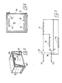
- the invention relates to household electric ovens comprising a cooking chamber which opens on its front face and which contains a heating element for the vault and at least one heating element for silk.
- the invention relates, more specifically, household ovens of this kind which further comprise a switch capable of occupying either an "oven operating" position for which at least the hearth resistance is supplied, or an "operating position in grill “for which only the vault resistance is supplied, while a door arranged on said front face is adapted to take, in particular, either a closed position or” oven operation "for which it is applied against the surrounding the front opening, either a half-open or "grill operation” position for which it leaves on this opening an air circulation space between the enclosure and the outside.
- the invention aims to eliminate these drawbacks.
- An oven according to the invention comprises movement transmission members arranged between the resistance control switch and the door and capable of ensuring that the passage of this switch from its operating position in the oven to its operating position in the grill automatically the passage of the door from its closed position to its ajar position.
- the oven shown comprises a cooking chamber 12 which opens on its front face and which contains a heating resistance of the roof 14 and two heating elements of the bottom 16 and 18. These resistances are controlled by a switch 20 (FIGS. 3 to 5) which is likely to occupy either an operating position in the oven ( Figure 4 and position A in Figure 3), or an operating position in the grill ( Figure 5 and position B in Figure 3).
- a switch 20 FIGGS. 3 to 5
- the resistor 16, on the one hand, and all of the resistors 14 and 18 in series, on the other hand are supplied in parallel on the mains voltage applied to the input terminals 22 and 24.
- For the grill operating position only the top heater 14 is supplied.
- the supply voltage is applied to the resistors through a thermostatic switch 26 (only a small part of which is shown in FIGS. 4 and 5) intended to regulating the temperature of the cooking chamber during operation in the oven.
- the cooking chamber 12 is equipped with a door 28 arranged on the front face and articulated around a horizontal axis 30 located in the vicinity of its lower edge.
- This door can take, in particular, either a closed position ( Figures 2 and 4) for which it is applied against the surround 32 of the front opening, or a half-open position ( Figures 1 and 5) for which it leaves on this opening an air circulation space 34 between the enclosure 12 and the outside.
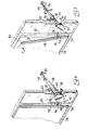
- the resistance control switch 20 is actuated by a movable key 36. This key is itself operated by a rotary shaft 38 which is itself coupled to the regulating switch 40 of the thermostatic switch 26.
- the shaft 38 is provided with a manipulation button 42 and carries a lateral projection 44 which, for a determined angular position of this shaft - (fig.5), comes to operate the key 36 of the switch 20 to bring this switch into its grill operating position (position B of the figure 3).
- This position corresponds to an angular position of the button 42 identified by the letter G, as can be seen in FIG. 5, on which a partial cutout of the shaft 38 has been carried out in order to clearly show the projection 44.
- the adjustment shaft 40 ensures, for this position, a blocking of the thermostatic switch 26 in a permanently closed position of this switch.
- the projection 44 releases the key 36 and thus leaves the switch 20 in its operating position in the oven (position A in FIG. 3), the thermostatic switch. 26 being itself also released to ensure temperature regulation as a function of the chosen setting: this choice is made by turning the button 42 to place it in correspondence with one or the other of numerical marks (for example 10 or 9, as in Figures 4 and 5).
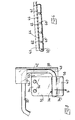
- These movement transmission members comprise a stay 46 mounted movably on the surround 32 of the front opening and mechanically linked to the control shaft 38 of the switch 20 so that, when this switch is in its operating position in oven ( Figure 4), the stay 46 is in a rest position, for which it is retracted to let the door 28 come to its closed position, and that, when this switch switches to its operating position on the grill ( Figure 5 ), the landlord 46 goes into an active position for which he is interposed between the surround 32 and the lateral edge 48 of the door 28 to cause this door to pivot outwards to its ajar position and to keep it in this position.
- the spacing 46 is constituted by a sliding rack whose teeth 50 are engaged with a toothed wheel 52 secured to the rotary shaft 38 and whose a free end pointed carries a inclined ramp 54 adapted to engage between the edge 48 of the door 28 and the surround 32 when the rack passes into its active position.
- the transmission members arranged between the switch 20 and the door 28, and constituted by the shaft 38, the toothed wheel 52, the rack 46, and the ramp 54, are adapted to ensure, not only that the passage of the switch 20 in its operating position in the grill causes the door to pass into its ajar position, but also, conversely, that the return of the door to its closed position causes the switch 20 to pass into its operating position in the oven.
Landscapes
- Engineering & Computer Science (AREA)
- Combustion & Propulsion (AREA)
- Mechanical Engineering (AREA)
- General Engineering & Computer Science (AREA)
- Chemical & Material Sciences (AREA)
- Electric Stoves And Ranges (AREA)
- Cookers (AREA)
- Organic Insulating Materials (AREA)
- Insulated Conductors (AREA)
- Glass Compositions (AREA)
- Inorganic Insulating Materials (AREA)
- Carbon And Carbon Compounds (AREA)
- Iron Core Of Rotating Electric Machines (AREA)
- Reciprocating, Oscillating Or Vibrating Motors (AREA)
- Physical Water Treatments (AREA)
- Vending Machines For Individual Products (AREA)
- Switches With Compound Operations (AREA)
Priority Applications (1)
| Application Number | Priority Date | Filing Date | Title |
|---|---|---|---|
| AT86104531T ATE62988T1 (de) | 1985-04-05 | 1986-04-03 | Elektrischer haushaltskochherd. |
Applications Claiming Priority (2)
| Application Number | Priority Date | Filing Date | Title |
|---|---|---|---|
| FR8505250A FR2580059B1 (de) | 1985-04-05 | 1985-04-05 | |
| FR8505250 | 1985-04-05 |
Publications (3)
| Publication Number | Publication Date |
|---|---|
| EP0200920A2 true EP0200920A2 (de) | 1986-11-12 |
| EP0200920A3 EP0200920A3 (en) | 1989-03-08 |
| EP0200920B1 EP0200920B1 (de) | 1991-04-24 |
Family
ID=9318016
Family Applications (1)
| Application Number | Title | Priority Date | Filing Date |
|---|---|---|---|
| EP86104531A Expired - Lifetime EP0200920B1 (de) | 1985-04-05 | 1986-04-03 | Elektrischer Haushaltskochherd |
Country Status (8)
| Country | Link |
|---|---|
| US (1) | US4659908A (de) |
| EP (1) | EP0200920B1 (de) |
| AT (1) | ATE62988T1 (de) |
| DE (1) | DE3678863D1 (de) |
| ES (1) | ES293372Y (de) |
| FR (1) | FR2580059B1 (de) |
| GB (1) | GB2173588B (de) |
| PT (1) | PT82332B (de) |
Cited By (2)
| Publication number | Priority date | Publication date | Assignee | Title |
|---|---|---|---|---|
| WO2009000610A3 (de) * | 2007-06-25 | 2009-11-19 | BSH Bosch und Siemens Hausgeräte GmbH | Hocheinbau-gargerät |
| FR2943486A1 (fr) * | 2009-03-23 | 2010-09-24 | Fagorbrandt Sas | Appareil de cuisson electromenager |
Families Citing this family (4)
| Publication number | Priority date | Publication date | Assignee | Title |
|---|---|---|---|---|
| DE8903653U1 (de) * | 1989-03-22 | 1989-05-11 | Bosch-Siemens Hausgeräte GmbH, 8000 München | Haushalt-Backofen |
| US5379685A (en) * | 1994-01-07 | 1995-01-10 | Black & Decker Inc. | Venting system for an electric toaster |
| DE102010061339A1 (de) | 2010-12-20 | 2012-06-21 | Miele & Cie. Kg | Gargerät und Verfahren zum Betreiben eines Gargerätes |
| US12207758B2 (en) * | 2021-06-17 | 2025-01-28 | Conair Llc | Multifunction toaster oven |
Family Cites Families (5)
| Publication number | Priority date | Publication date | Assignee | Title |
|---|---|---|---|---|
| US2262910A (en) * | 1939-01-14 | 1941-11-18 | Aller Simeon | Broiler |
| US2907859A (en) * | 1958-02-19 | 1959-10-06 | Gen Electric | Domestic appliance |
| US3660637A (en) * | 1971-03-10 | 1972-05-02 | Gen Electric | Electric oven toaster door operating mechanism |
| US3845272A (en) * | 1973-09-21 | 1974-10-29 | Gen Electric | Electric oven toaster bread rack and door mechanism |
| US4189632A (en) * | 1976-12-13 | 1980-02-19 | Sunbeam Corporation | Toaster oven |
-
1985
- 1985-04-05 FR FR8505250A patent/FR2580059B1/fr not_active Expired
-
1986
- 1986-03-26 GB GB08607532A patent/GB2173588B/en not_active Expired
- 1986-03-27 US US06/844,781 patent/US4659908A/en not_active Expired - Lifetime
- 1986-04-03 EP EP86104531A patent/EP0200920B1/de not_active Expired - Lifetime
- 1986-04-03 PT PT82332A patent/PT82332B/pt not_active IP Right Cessation
- 1986-04-03 DE DE8686104531T patent/DE3678863D1/de not_active Expired - Fee Related
- 1986-04-03 AT AT86104531T patent/ATE62988T1/de not_active IP Right Cessation
- 1986-04-04 ES ES1986293372U patent/ES293372Y/es not_active Expired
Cited By (2)
| Publication number | Priority date | Publication date | Assignee | Title |
|---|---|---|---|---|
| WO2009000610A3 (de) * | 2007-06-25 | 2009-11-19 | BSH Bosch und Siemens Hausgeräte GmbH | Hocheinbau-gargerät |
| FR2943486A1 (fr) * | 2009-03-23 | 2010-09-24 | Fagorbrandt Sas | Appareil de cuisson electromenager |
Also Published As
| Publication number | Publication date |
|---|---|
| EP0200920A3 (en) | 1989-03-08 |
| ES293372Y (es) | 1987-04-16 |
| GB8607532D0 (en) | 1986-04-30 |
| GB2173588A (en) | 1986-10-15 |
| ATE62988T1 (de) | 1991-05-15 |
| US4659908A (en) | 1987-04-21 |
| ES293372U (es) | 1986-08-01 |
| DE3678863D1 (de) | 1991-05-29 |
| PT82332A (fr) | 1986-05-01 |
| PT82332B (pt) | 1992-06-30 |
| GB2173588B (en) | 1988-10-05 |
| EP0200920B1 (de) | 1991-04-24 |
| FR2580059A1 (de) | 1986-10-10 |
| FR2580059B1 (de) | 1989-12-15 |
Similar Documents
| Publication | Publication Date | Title |
|---|---|---|
| EP0617909B1 (de) | Elektrisches Gargerät | |
| US3684860A (en) | Electric toaster with improved heat-up cool-down bimetal timer | |
| EP2900114B1 (de) | Elektrische haushaltskochvorrichtung | |
| FR2470575A1 (fr) | Appareil electrique de cuisson | |
| EP3756514A1 (de) | Elektrisches kochgerät, das mit einer abmontierbaren heizvorrichtung ausgestattet ist | |
| FR3097732A1 (fr) | Appareil de cuisson pour cuire des aliments avec ou sans pression. | |
| US4188867A (en) | Door mechanism for appliances | |
| JPS62284125A (ja) | ト−スタ−オ−ブン | |
| US20180325312A1 (en) | Double-Sided Electric Grill | |
| EP0200920A2 (de) | Elektrischer Haushaltskochherd | |
| FR2655805A1 (fr) | Circuit de commande d'element chauffant. | |
| EP0623303B1 (de) | Elektrisches Kochgerät | |
| FR2632510A1 (fr) | Grille-pain dont le chauffage est reglable en fonction de la forme et de la qualite des tranches de pain a griller | |
| FR2599477A1 (fr) | Dispositif de cuisson electrique a haut rendement plus specialement destine a des restaurateurs ou a des collectives | |
| EP0537796B1 (de) | Kochofen | |
| GB1095935A (en) | Improvements relating to temperature sensitive arrangements for cooking appliances | |
| FR2569932A1 (fr) | Dispositif de commande de temperature pour un four de cuisson | |
| EP0786629B1 (de) | Stromversorgung von Heizwiderständen für Unter- und Oberhitze an elektrischen Haushaltherden | |
| US2877703A (en) | Electric waffle baker | |
| FR2803994A1 (fr) | Caisson mobile pour le maintien en temperature et le rechauffage des plats cuisines | |
| JPS63118533A (ja) | ト−スタオ−ブン | |
| FR2495425A1 (fr) | Gril electrique pour aliments | |
| EP1298394A1 (de) | Haushaltsofen | |
| FR2661587A1 (fr) | Four de cuisson a resistances electriques de sole et/ou de voute. | |
| JPH0413010A (ja) | 調理器 |
Legal Events
| Date | Code | Title | Description |
|---|---|---|---|
| PUAI | Public reference made under article 153(3) epc to a published international application that has entered the european phase |
Free format text: ORIGINAL CODE: 0009012 |
|
| AK | Designated contracting states |
Kind code of ref document: A2 Designated state(s): AT BE CH DE IT LI NL SE |
|
| PUAB | Information related to the publication of an a document modified or deleted |
Free format text: ORIGINAL CODE: 0009199EPPU |
|
| RA1 | Application published (corrected) |
Date of ref document: 19861217 Kind code of ref document: A2 |
|
| PUAL | Search report despatched |
Free format text: ORIGINAL CODE: 0009013 |
|
| AK | Designated contracting states |
Kind code of ref document: A3 Designated state(s): AT BE CH DE IT LI NL SE |
|
| 17P | Request for examination filed |
Effective date: 19890131 |
|
| 17Q | First examination report despatched |
Effective date: 19891205 |
|
| GRAA | (expected) grant |
Free format text: ORIGINAL CODE: 0009210 |
|
| AK | Designated contracting states |
Kind code of ref document: B1 Designated state(s): AT BE CH DE IT LI NL SE |
|
| REF | Corresponds to: |
Ref document number: 62988 Country of ref document: AT Date of ref document: 19910515 Kind code of ref document: T |
|
| REF | Corresponds to: |
Ref document number: 3678863 Country of ref document: DE Date of ref document: 19910529 |
|
| ITF | It: translation for a ep patent filed | ||
| PLBE | No opposition filed within time limit |
Free format text: ORIGINAL CODE: 0009261 |
|
| STAA | Information on the status of an ep patent application or granted ep patent |
Free format text: STATUS: NO OPPOSITION FILED WITHIN TIME LIMIT |
|
| 26N | No opposition filed | ||
| EAL | Se: european patent in force in sweden |
Ref document number: 86104531.8 |
|
| PGFP | Annual fee paid to national office [announced via postgrant information from national office to epo] |
Ref country code: AT Payment date: 19960415 Year of fee payment: 11 |
|
| PG25 | Lapsed in a contracting state [announced via postgrant information from national office to epo] |
Ref country code: AT Effective date: 19970403 |
|
| PGFP | Annual fee paid to national office [announced via postgrant information from national office to epo] |
Ref country code: CH Payment date: 19970501 Year of fee payment: 12 |
|
| PG25 | Lapsed in a contracting state [announced via postgrant information from national office to epo] |
Ref country code: LI Free format text: LAPSE BECAUSE OF NON-PAYMENT OF DUE FEES Effective date: 19980430 Ref country code: CH Free format text: LAPSE BECAUSE OF NON-PAYMENT OF DUE FEES Effective date: 19980430 |
|
| REG | Reference to a national code |
Ref country code: CH Ref legal event code: PL |
|
| PGFP | Annual fee paid to national office [announced via postgrant information from national office to epo] |
Ref country code: SE Payment date: 19990412 Year of fee payment: 14 |
|
| PGFP | Annual fee paid to national office [announced via postgrant information from national office to epo] |
Ref country code: DE Payment date: 19990528 Year of fee payment: 14 |
|
| PGFP | Annual fee paid to national office [announced via postgrant information from national office to epo] |
Ref country code: BE Payment date: 19990614 Year of fee payment: 14 |
|
| PG25 | Lapsed in a contracting state [announced via postgrant information from national office to epo] |
Ref country code: SE Free format text: LAPSE BECAUSE OF NON-PAYMENT OF DUE FEES Effective date: 20000404 |
|
| PG25 | Lapsed in a contracting state [announced via postgrant information from national office to epo] |
Ref country code: BE Free format text: LAPSE BECAUSE OF NON-PAYMENT OF DUE FEES Effective date: 20000430 |
|
| BERE | Be: lapsed |
Owner name: MOULINEX Effective date: 20000430 |
|
| EUG | Se: european patent has lapsed |
Ref document number: 86104531.8 |
|
| PG25 | Lapsed in a contracting state [announced via postgrant information from national office to epo] |
Ref country code: DE Free format text: LAPSE BECAUSE OF NON-PAYMENT OF DUE FEES Effective date: 20010201 |
|
| PGFP | Annual fee paid to national office [announced via postgrant information from national office to epo] |
Ref country code: NL Payment date: 20010430 Year of fee payment: 16 |
|
| PG25 | Lapsed in a contracting state [announced via postgrant information from national office to epo] |
Ref country code: NL Free format text: LAPSE BECAUSE OF NON-PAYMENT OF DUE FEES Effective date: 20021101 |
|
| NLV4 | Nl: lapsed or anulled due to non-payment of the annual fee |
Effective date: 20021101 |
|
| PG25 | Lapsed in a contracting state [announced via postgrant information from national office to epo] |
Ref country code: IT Free format text: LAPSE BECAUSE OF NON-PAYMENT OF DUE FEES;WARNING: LAPSES OF ITALIAN PATENTS WITH EFFECTIVE DATE BEFORE 2007 MAY HAVE OCCURRED AT ANY TIME BEFORE 2007. THE CORRECT EFFECTIVE DATE MAY BE DIFFERENT FROM THE ONE RECORDED. Effective date: 20050403 |