EP0200969B1 - Dispositif de remplissage de bouteilles - Google Patents
Dispositif de remplissage de bouteilles Download PDFInfo
- Publication number
- EP0200969B1 EP0200969B1 EP86105324A EP86105324A EP0200969B1 EP 0200969 B1 EP0200969 B1 EP 0200969B1 EP 86105324 A EP86105324 A EP 86105324A EP 86105324 A EP86105324 A EP 86105324A EP 0200969 B1 EP0200969 B1 EP 0200969B1
- Authority
- EP
- European Patent Office
- Prior art keywords
- tank
- liquid
- bottle
- weight
- lug
- Prior art date
- Legal status (The legal status is an assumption and is not a legal conclusion. Google has not performed a legal analysis and makes no representation as to the accuracy of the status listed.)
- Expired
Links
Images

Classifications
-
- G—PHYSICS
- G01—MEASURING; TESTING
- G01F—MEASURING VOLUME, VOLUME FLOW, MASS FLOW OR LIQUID LEVEL; METERING BY VOLUME
- G01F23/00—Indicating or measuring liquid level or level of fluent solid material, e.g. indicating in terms of volume or indicating by means of an alarm
- G01F23/20—Indicating or measuring liquid level or level of fluent solid material, e.g. indicating in terms of volume or indicating by means of an alarm by measurement of weight, e.g. to determine the level of stored liquefied gas
-
- B—PERFORMING OPERATIONS; TRANSPORTING
- B65—CONVEYING; PACKING; STORING; HANDLING THIN OR FILAMENTARY MATERIAL
- B65B—MACHINES, APPARATUS OR DEVICES FOR, OR METHODS OF, PACKAGING ARTICLES OR MATERIALS; UNPACKING
- B65B3/00—Packaging plastic material, semiliquids, liquids or mixed solids and liquids, in individual containers or receptacles, e.g. bags, sacks, boxes, cartons, cans, or jars
- B65B3/26—Methods or devices for controlling the quantity of the material fed or filled
- B65B3/28—Methods or devices for controlling the quantity of the material fed or filled by weighing
Definitions
- This invention relates to a bottle filling device.
- a bottle filling device comprising at least one filling station as defined in Claim 1.
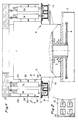
- the carousel main frame supported with the interposition of the bearing 2 on the bed 3 and driven rotatively in a known manner through the sprocket wheel 4, which has at its periphery a plurality of stations such as those indicated at 5 and 6.
- Each of these stations are loaded by known means with a box containing bottles to be filled; thus, the station 5 comprises a plate 7 supporting the box 8 containing four bottles of which the visible two are indicated at 9 and 10, and an arm 11 which operates in a manner known per se to take the plate 7 with the box 8, from an underlying position, to the position shown in Figure 1, with the necks of the bottles inserted into the flaring holes of the centering plate 12 rigid with the main frame 1.
- All the other stations, and among these the station indicated at 6 which carries the box 13 of bottles, are configured to an identical design.
- Each box is held in the station to which it has been loaded while rotation angle of the carousel is completed within such a time period as to allow for complete filling of the bottles with the liquid supplied from the tanks to be described hereinafter. Thereafter the box is unloaded by known means and delivered to storage.
- each of the bottles contained in one of the boxes positioned on the stations described a tank is provided which is adapted to feed with liquid, by gravity through a cock, the corresponding bottle.
- the four tanks overlying the four bottles in the box 8 are indicated at 14, 15, 16, 17, of which in particular the ones indicated at 14 and 15 overlie the visible bottles 9 and 10, and indicated at 18 and 19 are two tanks out of the four which overlie the four bottles in the box 13.
- Said tank 14 comprises, therefore, the cock for feeding with liquid the underlying bottle, formed of a passageway 20 with a shutter 21 at the lower end of a rod 22 driven upwards by an electromagnet 23 upon consent from the automatic control system of the device to start the filling step, and downwards by its own weight and by the weight of a block 24 rigid therewith to cut off the outflow of liquid in conformity with what will be specified hereinafter.
- the tank 14 contains an amount of liquid capable of producing a right value of outflow velocity from the cock, and topping up of the liquid in the tank in substantially equal amounts to the exiting amount for filling a bottle is effected, during the time intervals when the passageway 20 is closed, througipassageway 20 is closed, through a conduit 25 controlled by a valve 26 which branches out from a main tank 27 supported on the carousel structure.
- the tank herein is connected kinematically to a rigid wall 28 which forms a part of the peripheral frame of the carousel, through means adapted to allow for it a translatory movement in the vertical direction, albeit composited with a quite negligible horizontal component.
- this means comprises rocker arms 29 and 30 journalled at 29a and 30a to said wall and at 29b and 30b to the tank, and said tank is provided with a shelf 31 which rests upon a lug 32a of an instrument known per se generally indicated at 32, which is attached with another lug 32b thereof to the shelf 28a rigid with the wall 28.
- the instrument 32 which may be for example of the type called "load cell” identified with the symbol 26-4 manufactured by Firma Hottinger Baldwin Messtechnik GmbH, is adapted to send an electric signal proportional to the deflection of the lug 32a caused by the weight of the tank 14 bearing on it to a control unit for the electromagnet 23 which determines the closure of the shutter upon the weight of the liquid which has come out of the tank to pass by gravity into the underlying bottle reaching the preset value.
- the tank 15 is connected kinematically to the main frame 1 of the carousel through analogous rocker arms 33 and 34, and bears on one lug of an instrument 35 attached with the other lug to said frame 1.
- the invention also enables the realization of devices for in-line filling with a particularly simplified construction; an example therefor is the device shown in Figure 4 suitable for small and medium production rates.
- an example therefor is the device shown in Figure 4 suitable for small and medium production rates.
- at 36, 37, 38 are indicated three bottles supported on a conveyor belt 39, at a standstill in contact with a spacer member consisting of an auger 40 and ready to be definitively centered by the advancement of detents 41, 42, 43 which contact the bottle necks urging them against a stationary rod 44.
- tanks 45, 46, 47 of the type described in the foregoing with reference to Figure 3, all connected kinematically to a fixed wall 48 of the frame of the device by means of rocker arms such as 49 and 49a for the tank 45, and operating in combination with instruments such as 50 for said tank 45.
- this in-line device is particularly simple because, thanks to the fact that the weighing out of the liquid to be delivered to each individual bottle is effected above and independently of the bottle itself, it allows holding the bottles in contact with the transport, spacer and centering members, without the need for solving the problems of bottle isolation while weighing out, which impose a considerable constructional complication on the known machines.
- the device according to this invention finds advantageous application also to carousel fillers with stations adapted to receive a single bottle; in the known types, in fact, the weighing out of each individual bottle is carried out by an instrument, which may be for example of the load-cell type mentioned above, connected to the plate with which each station is equipped for supporting the bottles, and this arrangement may originate problems such as breakage of the instrument on the occurrence of a malfunction in the bottle handling by the members for loading and unloading the same onto/ from the plates; in the device according to the invention, by contrast, the instruments are totally isolated from the bottles, and are arranged to operate in ideal conditions which are unaffected by the manipulations to which said bottles are subjected, and therefore solving the above drawbacks.
- each bottle could be connected kinematically to the device frame, it being attached to the lugs of two load cells attached with the other lugs to said frame.
Landscapes
- Engineering & Computer Science (AREA)
- Mechanical Engineering (AREA)
- Physics & Mathematics (AREA)
- Fluid Mechanics (AREA)
- General Physics & Mathematics (AREA)
- Filling Of Jars Or Cans And Processes For Cleaning And Sealing Jars (AREA)
- Basic Packing Technique (AREA)
Claims (7)
Applications Claiming Priority (2)
| Application Number | Priority Date | Filing Date | Title |
|---|---|---|---|
| IT18107/85A IT1187119B (it) | 1985-04-22 | 1985-04-22 | Dispositivo per il riempimento di bottiglie |
| IT1810785 | 1985-04-22 |
Publications (2)
| Publication Number | Publication Date |
|---|---|
| EP0200969A1 EP0200969A1 (fr) | 1986-11-12 |
| EP0200969B1 true EP0200969B1 (fr) | 1989-06-07 |
Family
ID=11151872
Family Applications (1)
| Application Number | Title | Priority Date | Filing Date |
|---|---|---|---|
| EP86105324A Expired EP0200969B1 (fr) | 1985-04-22 | 1986-04-17 | Dispositif de remplissage de bouteilles |
Country Status (3)
| Country | Link |
|---|---|
| EP (1) | EP0200969B1 (fr) |
| DE (1) | DE3663788D1 (fr) |
| IT (1) | IT1187119B (fr) |
Families Citing this family (1)
| Publication number | Priority date | Publication date | Assignee | Title |
|---|---|---|---|---|
| JPS6367295A (ja) * | 1986-09-08 | 1988-03-26 | 三菱重工業株式会社 | 液体充填方法及び装置 |
Family Cites Families (2)
| Publication number | Priority date | Publication date | Assignee | Title |
|---|---|---|---|---|
| US3776324A (en) * | 1972-11-16 | 1973-12-04 | A Bruestle | Automatic loader for cartons |
| DE3227025C2 (de) * | 1982-07-20 | 1985-06-13 | Wilhelm Dipl.-Ing. 4000 Düsseldorf Frede | Verfahren zur Ermittlung des Flächengewichtes oder der Schichtdicke einer beschichteten Materialbahn |
-
1985
- 1985-04-22 IT IT18107/85A patent/IT1187119B/it active
-
1986
- 1986-04-17 DE DE8686105324T patent/DE3663788D1/de not_active Expired
- 1986-04-17 EP EP86105324A patent/EP0200969B1/fr not_active Expired
Also Published As
| Publication number | Publication date |
|---|---|
| IT1187119B (it) | 1987-12-16 |
| DE3663788D1 (en) | 1989-07-13 |
| EP0200969A1 (fr) | 1986-11-12 |
| IT8518107A0 (it) | 1985-04-22 |
Similar Documents
| Publication | Publication Date | Title |
|---|---|---|
| EP1288125B1 (fr) | Machine de remplissage avec des unités de remplissages multiples contrôlées par pesage | |
| EP0260532B1 (fr) | Dispositif de remplissage de liquides | |
| US5156193A (en) | Method for filling containers with liquid, gelatinous, corrosive, and/or sticky products, or abrasive suspensions | |
| US4230195A (en) | Automatic control method and device for a container filling apparatus | |
| US5111855A (en) | Plant and apparatus for producing perfumes | |
| EP1243546B1 (fr) | Machine de remplissage | |
| EP3977067A2 (fr) | Procédé de pesage de contenants | |
| US20030150514A1 (en) | Installation for filling receptacles with varying product compositions | |
| US3339651A (en) | Weighing apparatus | |
| JPS61284615A (ja) | 流動性の生成物を重量により配量する装置 | |
| US4676282A (en) | Apparatus and method for filling bottles, flacons or the like container with a predetermined weight amount of a fluid | |
| EP0200969B1 (fr) | Dispositif de remplissage de bouteilles | |
| EP1702880B1 (fr) | Machine de remplissage de récipients avec des produits liquides ou pulvérulents | |
| CN218929879U (zh) | 一种新型电子组合称 | |
| US4635689A (en) | Method and apparatus for monitoring and controlling the filling of receptacles with a determined weight of material | |
| JP4461571B2 (ja) | 充填方法および充填装置 | |
| ES8203304A1 (es) | Perfeccionamientos en las maquinas para llenar o vaciar re- cipientes con objetos ordenados | |
| EP0298407A2 (fr) | Procédé et appareil pour le dosage à poids net de liquides | |
| CA1215692A (fr) | Methode et dispositif de remplissage de recipients | |
| US4526213A (en) | Weighing dividing machines | |
| US2661201A (en) | Check weigher | |
| WO2001094895A1 (fr) | Balance a combinaison servant a peser des produits en vrac de forme allongee tels que des pates ou analogue | |
| US3109561A (en) | Apparatus for weighing out and discharging pourable material | |
| JPH069332Y2 (ja) | 物品供給装置 | |
| JP2651285B2 (ja) | 液体充填装置 |
Legal Events
| Date | Code | Title | Description |
|---|---|---|---|
| PUAI | Public reference made under article 153(3) epc to a published international application that has entered the european phase |
Free format text: ORIGINAL CODE: 0009012 |
|
| AK | Designated contracting states |
Kind code of ref document: A1 Designated state(s): BE DE FR GB NL |
|
| 17P | Request for examination filed |
Effective date: 19870506 |
|
| 17Q | First examination report despatched |
Effective date: 19880219 |
|
| GRAA | (expected) grant |
Free format text: ORIGINAL CODE: 0009210 |
|
| AK | Designated contracting states |
Kind code of ref document: B1 Designated state(s): BE DE FR GB NL |
|
| REF | Corresponds to: |
Ref document number: 3663788 Country of ref document: DE Date of ref document: 19890713 |
|
| ET | Fr: translation filed | ||
| PLBE | No opposition filed within time limit |
Free format text: ORIGINAL CODE: 0009261 |
|
| STAA | Information on the status of an ep patent application or granted ep patent |
Free format text: STATUS: NO OPPOSITION FILED WITHIN TIME LIMIT |
|
| 26N | No opposition filed | ||
| PGFP | Annual fee paid to national office [announced via postgrant information from national office to epo] |
Ref country code: GB Payment date: 19950407 Year of fee payment: 10 |
|
| PGFP | Annual fee paid to national office [announced via postgrant information from national office to epo] |
Ref country code: BE Payment date: 19950412 Year of fee payment: 10 |
|
| PGFP | Annual fee paid to national office [announced via postgrant information from national office to epo] |
Ref country code: FR Payment date: 19950418 Year of fee payment: 10 |
|
| PGFP | Annual fee paid to national office [announced via postgrant information from national office to epo] |
Ref country code: NL Payment date: 19950430 Year of fee payment: 10 |
|
| PGFP | Annual fee paid to national office [announced via postgrant information from national office to epo] |
Ref country code: DE Payment date: 19950504 Year of fee payment: 10 |
|
| PG25 | Lapsed in a contracting state [announced via postgrant information from national office to epo] |
Ref country code: GB Effective date: 19960417 |
|
| PG25 | Lapsed in a contracting state [announced via postgrant information from national office to epo] |
Ref country code: BE Effective date: 19960430 |
|
| BERE | Be: lapsed |
Owner name: CORNIANI S.R.L. Effective date: 19960430 |
|
| PG25 | Lapsed in a contracting state [announced via postgrant information from national office to epo] |
Ref country code: NL Effective date: 19961101 |
|
| GBPC | Gb: european patent ceased through non-payment of renewal fee |
Effective date: 19960417 |
|
| PG25 | Lapsed in a contracting state [announced via postgrant information from national office to epo] |
Ref country code: FR Effective date: 19961227 |
|
| PG25 | Lapsed in a contracting state [announced via postgrant information from national office to epo] |
Ref country code: DE Effective date: 19970101 |
|
| NLV4 | Nl: lapsed or anulled due to non-payment of the annual fee |
Effective date: 19961101 |
|
| REG | Reference to a national code |
Ref country code: FR Ref legal event code: ST |