EP0201023A1 - Plaque d'ostéosynthèse pour stabilisation à compression - Google Patents
Plaque d'ostéosynthèse pour stabilisation à compression Download PDFInfo
- Publication number
- EP0201023A1 EP0201023A1 EP86105850A EP86105850A EP0201023A1 EP 0201023 A1 EP0201023 A1 EP 0201023A1 EP 86105850 A EP86105850 A EP 86105850A EP 86105850 A EP86105850 A EP 86105850A EP 0201023 A1 EP0201023 A1 EP 0201023A1
- Authority
- EP
- European Patent Office
- Prior art keywords
- ramp
- bone
- compression
- screw
- plate
- Prior art date
- Legal status (The legal status is an assumption and is not a legal conclusion. Google has not performed a legal analysis and makes no representation as to the accuracy of the status listed.)
- Granted
Links
- 230000006641 stabilisation Effects 0.000 title claims abstract description 6
- 230000006835 compression Effects 0.000 title abstract description 14
- 238000007906 compression Methods 0.000 title abstract description 14
- 230000001097 osteosynthetic effect Effects 0.000 title 1
- 210000000988 bone and bone Anatomy 0.000 claims abstract description 32
- 239000012634 fragment Substances 0.000 claims abstract description 15
- 238000011105 stabilization Methods 0.000 claims abstract description 5
- 238000000926 separation method Methods 0.000 claims 1
- 230000006837 decompression Effects 0.000 description 1
- 238000006073 displacement reaction Methods 0.000 description 1
- 230000035876 healing Effects 0.000 description 1
- 210000004394 hip joint Anatomy 0.000 description 1
Images
Classifications
-
- A—HUMAN NECESSITIES
- A61—MEDICAL OR VETERINARY SCIENCE; HYGIENE
- A61B—DIAGNOSIS; SURGERY; IDENTIFICATION
- A61B17/00—Surgical instruments, devices or methods
- A61B17/56—Surgical instruments or methods for treatment of bones or joints; Devices specially adapted therefor
- A61B17/58—Surgical instruments or methods for treatment of bones or joints; Devices specially adapted therefor for osteosynthesis, e.g. bone plates, screws or setting implements
- A61B17/68—Internal fixation devices, including fasteners and spinal fixators, even if a part thereof projects from the skin
- A61B17/80—Cortical plates, i.e. bone plates; Instruments for holding or positioning cortical plates, or for compressing bones attached to cortical plates
- A61B17/8004—Cortical plates, i.e. bone plates; Instruments for holding or positioning cortical plates, or for compressing bones attached to cortical plates with means for distracting or compressing the bone or bones
- A61B17/8014—Cortical plates, i.e. bone plates; Instruments for holding or positioning cortical plates, or for compressing bones attached to cortical plates with means for distracting or compressing the bone or bones the extension or compression force being caused by interaction of the plate hole and the screws
Definitions
- the invention relates to an osteosynthesis plate for the pressure stabilization of bone fragments.
- Clamping devices which, in conjunction with osteosynthesis plates, enable the pressure stabilization of the bone fragments.
- These include osteosynthesis plates; whose screw holes have inclined hole walls in the manner of an inclined plane, hereinafter referred to as ramps, so that when a bone screw is screwed in, the screw head slides on the ramp and thus a displacement of the plate in relation to the bone receiving the bone screw fragment causes.
- the largest possible compression path which is determined by the hole geometry and the thickness of the plate, is very short. - Larger compression stretches can be achieved with the help of a special clamping device, which is attached to the osteosynthesis plate.
- this device When this device is screwed to a bone fragment outside the bone plate, it has the disadvantage of a larger wound, greater surgical effort and a longer operating time. If it is attached in the area of the osteosynthesis plate in connection with an elongated hole provided in it (DE-OS 31 34 120), depending on the type of fracture and the position of the elongated hole, there may be a restricted supply option.
- the invention has for its object to provide an osteosynthesis plate that uses the simplicity and proven effectiveness of the ramp holes for pressure stabilization and still allows a larger compression distance.
- the solution according to the invention is that a plurality of elongated holes assigned to the same bone fragment are provided, each having a plurality of ramp hole sections, the spacing between the ramp hole sections belonging to the same elongated hole being no greater than the number of elongated holes assigned to the same bone fragment multiplied by the usable ramp length.
- the pitch distances of the ramp hole sections are expediently less than twice the usable ramp length.
- the osteosynthesis plate according to the invention is used in such a way that bone screws are alternately screwed in and loosened in the different elongated holes. will. After a first bone screw has been screwed into a ramp hole section close to the fracture within a first slot, whereby a first compression step has been carried out, a second bone screw is inserted in another slot so that it engages in the beginning of a ramp. Then the first screw is loosened and a second compression step is carried out by screwing in the second screw.
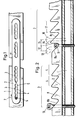
- the osteosynthesis plate 2 lying on a bone 1 with a transverse fracture in FIG. 1 contains in its sections assigned to each of the two bone fragments two elongated holes 3, each with four hole sections 4, which are each recognizable as a pair of opposing boundary arches 5 and each with one Ramp are equipped and therefore are referred to here as ramp hole sections.
- the ramps on the left in FIG. 1 are arranged falling to the right, while the ramps on the right side are arranged falling to the left, so that when the bone screw arranged at 6 in FIG. 1 is screwed in, the associated bone fragments move in the direction of the arrow 7, that is, in the compression direction. Details of this Function will now be illustrated with reference to FIG. 2, which represents the left section of the osteosynthesis plate in FIG. 1 - greatly enlarged compared to bone 1.
- the areas in which the elongated holes 3 are located are indicated in FIG. 2 by corresponding brackets.
- In the respective ramp hole sections 4 are zugeord - Neten ramps 8 as inclined planes recognizable.
- a first bone screw is inserted into the right-hand elongated hole in FIG. 2 in the end distal to the fracture in position 10.
- it slides with its screw head down the inclined plane 8a and thereby takes the underlying bone 1 with it, which thereby causes the Route 12 is moved in the direction of the arrow.
- the second bone screw is inserted over the elongated hole on the left in the drawing at its end distal to the fracture in item 13 and screwed in until it strikes the associated inclined plane 8b and thereby secures the bone 1 in the position reached against the osteosynthesis plate.
- the first screw is loosened up to item 14, in which it is located freely above the plate.
- the usable ramp length is in each case approximately equal to sections 12 or 15 or a little larger. It is the distance that the bone is displaced from the osteosynthesis plate when a screw moves from the extreme end of a ramp to the extreme other end of the same ramp.
- the spacing between two ramp hole sections is denoted by 17 in FIG. 2.
Landscapes
- Health & Medical Sciences (AREA)
- Orthopedic Medicine & Surgery (AREA)
- Surgery (AREA)
- Life Sciences & Earth Sciences (AREA)
- Heart & Thoracic Surgery (AREA)
- Animal Behavior & Ethology (AREA)
- Engineering & Computer Science (AREA)
- Biomedical Technology (AREA)
- Neurology (AREA)
- Medical Informatics (AREA)
- Molecular Biology (AREA)
- Nuclear Medicine, Radiotherapy & Molecular Imaging (AREA)
- General Health & Medical Sciences (AREA)
- Public Health (AREA)
- Veterinary Medicine (AREA)
- Surgical Instruments (AREA)
- Treatments For Attaching Organic Compounds To Fibrous Goods (AREA)
- Reinforced Plastic Materials (AREA)
- Polishing Bodies And Polishing Tools (AREA)
Priority Applications (1)
| Application Number | Priority Date | Filing Date | Title |
|---|---|---|---|
| AT86105850T ATE40036T1 (de) | 1985-05-06 | 1986-04-28 | Osteosyntheseplatte fuer die druckstabilisierung. |
Applications Claiming Priority (2)
| Application Number | Priority Date | Filing Date | Title |
|---|---|---|---|
| DE8513286U | 1985-05-06 | ||
| DE8513286U DE8513286U1 (de) | 1985-05-06 | 1985-05-06 | Osteosyntheseplatte für die Druckstabilisierung |
Publications (2)
| Publication Number | Publication Date |
|---|---|
| EP0201023A1 true EP0201023A1 (fr) | 1986-11-12 |
| EP0201023B1 EP0201023B1 (fr) | 1989-01-18 |
Family
ID=6780723
Family Applications (1)
| Application Number | Title | Priority Date | Filing Date |
|---|---|---|---|
| EP86105850A Expired EP0201023B1 (fr) | 1985-05-06 | 1986-04-28 | Plaque d'ostéosynthèse pour stabilisation à compression |
Country Status (4)
| Country | Link |
|---|---|
| US (1) | US4705031A (fr) |
| EP (1) | EP0201023B1 (fr) |
| AT (1) | ATE40036T1 (fr) |
| DE (2) | DE8513286U1 (fr) |
Cited By (2)
| Publication number | Priority date | Publication date | Assignee | Title |
|---|---|---|---|---|
| EP0374084A1 (fr) * | 1988-11-11 | 1990-06-20 | Joachim Dr.-Med. Schmidt | Plaque à trous coulissante pour l'ostéosynthèse |
| US9855082B2 (en) | 2009-05-12 | 2018-01-02 | DePuy Synthes Products, Inc. | Readjustable locking plate hole |
Families Citing this family (14)
| Publication number | Priority date | Publication date | Assignee | Title |
|---|---|---|---|---|
| US5015248A (en) * | 1990-06-11 | 1991-05-14 | New York Society For The Relief Of The Ruptured & Crippled, Maintaining The Hospital For Special Surgery | Bone fracture fixation device |
| WO1994010913A1 (fr) * | 1992-11-12 | 1994-05-26 | Neville Alleyne | Dispositif de protection cardiaque |
| US5611354A (en) * | 1992-11-12 | 1997-03-18 | Alleyne; Neville | Cardiac protection device |
| US5951557A (en) * | 1997-12-30 | 1999-09-14 | Luter; Dennis W. | Bone plate |
| US7717945B2 (en) | 2002-07-22 | 2010-05-18 | Acumed Llc | Orthopedic systems |
| AUPR546601A0 (en) * | 2001-06-05 | 2001-06-28 | Australian Surgical Design And Manufacture Pty Limited | High tibial osteotomy device |
| AU2003268480A1 (en) * | 2002-09-06 | 2004-03-29 | Neville D. Alleyne | Seal for posterior lateral vertebral disk cavity |
| AU2004249313B2 (en) * | 2003-06-20 | 2009-01-15 | Acumed Llc | Bone plates with intraoperatively tapped apertures |
| US20050177155A1 (en) * | 2003-10-28 | 2005-08-11 | Neville Alleyne | Anterior adhesion resistant barrier for spine |
| US20070198016A1 (en) * | 2006-02-21 | 2007-08-23 | Osteomed, L.P. | Compression stabilizing spacers |
| WO2009146135A2 (fr) * | 2008-04-04 | 2009-12-03 | Skeletal Dynamics Llc | Système d’ostéotomie par compression/distraction, plaque, procédé, guide-foret et guide-scie |
| US20100057133A1 (en) * | 2008-08-26 | 2010-03-04 | Simon William H | Tibia-talus-calcaneus (T-T-C) locking plate |
| US10869702B2 (en) | 2017-05-12 | 2020-12-22 | Nextremity Solutions, Inc. | Compression force magnifier |
| US11202664B2 (en) | 2018-12-17 | 2021-12-21 | Nextremity Solutions, Inc. | Compression force magnifier |
Citations (4)
| Publication number | Priority date | Publication date | Assignee | Title |
|---|---|---|---|---|
| US3528085A (en) * | 1968-03-22 | 1970-09-08 | Walker Reynolds Jr | Bone compression plate |
| US3547114A (en) * | 1967-07-07 | 1970-12-15 | Edward J Haboush | Compensating plate means for bone fractures |
| US3604414A (en) * | 1968-08-29 | 1971-09-14 | Nicomedes Borges | Bone setting device |
| DE8309326U1 (de) * | 1983-03-29 | 1984-10-25 | Waldemar Link (Gmbh & Co), 2000 Hamburg | Platte für die Spondylodese der Wirbelsäule |
Family Cites Families (4)
| Publication number | Priority date | Publication date | Assignee | Title |
|---|---|---|---|---|
| FR1505513A (fr) * | 1966-11-02 | 1967-12-15 | Benoist & Girard Reunis | Plaque d'ostéosynthèse |
| GB1571713A (en) * | 1976-04-21 | 1980-07-16 | Gil J L | Apparatus for use in the treatment of bone fractures |
| ZA80327B (en) * | 1979-08-23 | 1981-09-30 | U Mennen | Internal fixation device for bone fractures |
| IT1132843B (it) * | 1980-09-15 | 1986-07-09 | Cise Spa | Placca per giunzioni di porzioni d'osso separate da frattura |
-
1985
- 1985-05-06 DE DE8513286U patent/DE8513286U1/de not_active Expired
-
1986
- 1986-04-28 AT AT86105850T patent/ATE40036T1/de not_active IP Right Cessation
- 1986-04-28 DE DE8686105850T patent/DE3661793D1/de not_active Expired
- 1986-04-28 EP EP86105850A patent/EP0201023B1/fr not_active Expired
- 1986-05-05 US US06/859,650 patent/US4705031A/en not_active Expired - Lifetime
Patent Citations (4)
| Publication number | Priority date | Publication date | Assignee | Title |
|---|---|---|---|---|
| US3547114A (en) * | 1967-07-07 | 1970-12-15 | Edward J Haboush | Compensating plate means for bone fractures |
| US3528085A (en) * | 1968-03-22 | 1970-09-08 | Walker Reynolds Jr | Bone compression plate |
| US3604414A (en) * | 1968-08-29 | 1971-09-14 | Nicomedes Borges | Bone setting device |
| DE8309326U1 (de) * | 1983-03-29 | 1984-10-25 | Waldemar Link (Gmbh & Co), 2000 Hamburg | Platte für die Spondylodese der Wirbelsäule |
Cited By (4)
| Publication number | Priority date | Publication date | Assignee | Title |
|---|---|---|---|---|
| EP0374084A1 (fr) * | 1988-11-11 | 1990-06-20 | Joachim Dr.-Med. Schmidt | Plaque à trous coulissante pour l'ostéosynthèse |
| US4957496A (en) * | 1988-11-11 | 1990-09-18 | Mecron Medizinische Produkte Gmbh | Slotted slide plate assembly for osteosynthesis |
| US9855082B2 (en) | 2009-05-12 | 2018-01-02 | DePuy Synthes Products, Inc. | Readjustable locking plate hole |
| US10799275B2 (en) | 2009-05-12 | 2020-10-13 | DePuy Synthes Products, Inc. | Readjustable locking plate hole |
Also Published As
| Publication number | Publication date |
|---|---|
| ATE40036T1 (de) | 1989-02-15 |
| EP0201023B1 (fr) | 1989-01-18 |
| DE8513286U1 (de) | 1986-09-04 |
| US4705031A (en) | 1987-11-10 |
| DE3661793D1 (en) | 1989-02-23 |
Similar Documents
| Publication | Publication Date | Title |
|---|---|---|
| EP0201023B1 (fr) | Plaque d'ostéosynthèse pour stabilisation à compression | |
| EP0374084B1 (fr) | Plaque à trous coulissante pour l'ostéosynthèse | |
| DE3713351C2 (fr) | ||
| DE69712295T2 (de) | Verriegelbarer Marknagel mit verstellbaren Öffnungen für Verriegelungsschrauben | |
| EP0920284B1 (fr) | Plaque vissee pour le calcaneum | |
| DE69623374T2 (de) | Intramedulläre Knochenstütze | |
| DE2712696C3 (de) | Kieferdehnschraube | |
| EP0207884A2 (fr) | Plaque d'ostéosynthèse autoserrable | |
| DE1566153B1 (de) | Osteosynthetische Druckplatte | |
| DD218274A5 (de) | Aeussere orthopaedische befestigungsvorrichtung | |
| DE2808971A1 (de) | Distensions- und kompressionsplatte fuer die knochenchirurgie | |
| DE69610988T2 (de) | Kontaktkopf zur herstellung eines elektrisches mehrfachkontaktes an einem leitfähigen gegenstand, sowie ein mit ein solche kontaktkopf versehenes mittel | |
| DE69212158T2 (de) | Vorrichtung um brettartige elemente zu einer einheit zu verbinden | |
| DE2413219A1 (de) | Tafel fuer elektrische verbindungen | |
| EP0154813A1 (fr) | Dispositif de fixation pour machine-outil | |
| EP0659644A1 (fr) | Dispositif pour former des groupes de cigarettes | |
| AT411094B (de) | Steckverbindung | |
| DE60202051T2 (de) | Sensorträger | |
| EP0423474A1 (fr) | Dispositif pour relier deux baguettes profilées de façon à ce qu'elles soient détachables | |
| DE3038121C2 (de) | Befestigungsvorrichtung für eine Räumleiste | |
| DE3809037C2 (fr) | ||
| DE102018007133B4 (de) | Streifenförmiger Bauteilträger | |
| DE3516088C2 (de) | Behälter zur Aufbewahrung chirurgischer Instrumente | |
| DE3139575C2 (fr) | ||
| DE2649149A1 (de) | Anschlag fuer in einer schiene einer gardinenleiste laufende befestigungselemente |
Legal Events
| Date | Code | Title | Description |
|---|---|---|---|
| PUAI | Public reference made under article 153(3) epc to a published international application that has entered the european phase |
Free format text: ORIGINAL CODE: 0009012 |
|
| AK | Designated contracting states |
Kind code of ref document: A1 Designated state(s): AT BE CH DE FR GB IT LI NL SE |
|
| 17P | Request for examination filed |
Effective date: 19870205 |
|
| 17Q | First examination report despatched |
Effective date: 19880510 |
|
| GRAA | (expected) grant |
Free format text: ORIGINAL CODE: 0009210 |
|
| AK | Designated contracting states |
Kind code of ref document: B1 Designated state(s): AT BE CH DE FR GB IT LI NL SE |
|
| PG25 | Lapsed in a contracting state [announced via postgrant information from national office to epo] |
Ref country code: SE Effective date: 19890118 |
|
| REF | Corresponds to: |
Ref document number: 40036 Country of ref document: AT Date of ref document: 19890215 Kind code of ref document: T |
|
| REF | Corresponds to: |
Ref document number: 3661793 Country of ref document: DE Date of ref document: 19890223 |
|
| ITF | It: translation for a ep patent filed | ||
| GBT | Gb: translation of ep patent filed (gb section 77(6)(a)/1977) | ||
| ET | Fr: translation filed | ||
| PLBE | No opposition filed within time limit |
Free format text: ORIGINAL CODE: 0009261 |
|
| STAA | Information on the status of an ep patent application or granted ep patent |
Free format text: STATUS: NO OPPOSITION FILED WITHIN TIME LIMIT |
|
| 26N | No opposition filed | ||
| ITTA | It: last paid annual fee | ||
| PGFP | Annual fee paid to national office [announced via postgrant information from national office to epo] |
Ref country code: NL Payment date: 19920430 Year of fee payment: 7 |
|
| PGFP | Annual fee paid to national office [announced via postgrant information from national office to epo] |
Ref country code: BE Payment date: 19920604 Year of fee payment: 7 |
|
| PG25 | Lapsed in a contracting state [announced via postgrant information from national office to epo] |
Ref country code: BE Effective date: 19930430 |
|
| PGFP | Annual fee paid to national office [announced via postgrant information from national office to epo] |
Ref country code: GB Payment date: 19931015 Year of fee payment: 8 |
|
| PGFP | Annual fee paid to national office [announced via postgrant information from national office to epo] |
Ref country code: FR Payment date: 19931029 Year of fee payment: 8 |
|
| BERE | Be: lapsed |
Owner name: WOLTER DIETMAR Effective date: 19930430 |
|
| PG25 | Lapsed in a contracting state [announced via postgrant information from national office to epo] |
Ref country code: NL Effective date: 19931101 |
|
| NLV4 | Nl: lapsed or anulled due to non-payment of the annual fee | ||
| PG25 | Lapsed in a contracting state [announced via postgrant information from national office to epo] |
Ref country code: GB Effective date: 19940428 |
|
| PG25 | Lapsed in a contracting state [announced via postgrant information from national office to epo] |
Ref country code: FR Effective date: 19941229 |
|
| GBPC | Gb: european patent ceased through non-payment of renewal fee |
Effective date: 19940428 |
|
| REG | Reference to a national code |
Ref country code: FR Ref legal event code: ST |
|
| PGFP | Annual fee paid to national office [announced via postgrant information from national office to epo] |
Ref country code: AT Payment date: 19980623 Year of fee payment: 13 |
|
| PG25 | Lapsed in a contracting state [announced via postgrant information from national office to epo] |
Ref country code: AT Free format text: LAPSE BECAUSE OF NON-PAYMENT OF DUE FEES Effective date: 19990428 |
|
| PGFP | Annual fee paid to national office [announced via postgrant information from national office to epo] |
Ref country code: CH Payment date: 20000523 Year of fee payment: 15 |
|
| PG25 | Lapsed in a contracting state [announced via postgrant information from national office to epo] |
Ref country code: LI Free format text: LAPSE BECAUSE OF NON-PAYMENT OF DUE FEES Effective date: 20010527 Ref country code: CH Free format text: LAPSE BECAUSE OF NON-PAYMENT OF DUE FEES Effective date: 20010527 |
|
| PGFP | Annual fee paid to national office [announced via postgrant information from national office to epo] |
Ref country code: DE Payment date: 20010619 Year of fee payment: 16 |
|
| REG | Reference to a national code |
Ref country code: CH Ref legal event code: PL |
|
| PG25 | Lapsed in a contracting state [announced via postgrant information from national office to epo] |
Ref country code: DE Free format text: LAPSE BECAUSE OF NON-PAYMENT OF DUE FEES Effective date: 20021101 |
|
| PG25 | Lapsed in a contracting state [announced via postgrant information from national office to epo] |
Ref country code: IT Free format text: LAPSE BECAUSE OF NON-PAYMENT OF DUE FEES;WARNING: LAPSES OF ITALIAN PATENTS WITH EFFECTIVE DATE BEFORE 2007 MAY HAVE OCCURRED AT ANY TIME BEFORE 2007. THE CORRECT EFFECTIVE DATE MAY BE DIFFERENT FROM THE ONE RECORDED. Effective date: 20050428 |