EP0201235A2 - Séparation d'un mélange gazeux - Google Patents
Séparation d'un mélange gazeux Download PDFInfo
- Publication number
- EP0201235A2 EP0201235A2 EP86302963A EP86302963A EP0201235A2 EP 0201235 A2 EP0201235 A2 EP 0201235A2 EP 86302963 A EP86302963 A EP 86302963A EP 86302963 A EP86302963 A EP 86302963A EP 0201235 A2 EP0201235 A2 EP 0201235A2
- Authority
- EP
- European Patent Office
- Prior art keywords
- bed
- gas
- reservoir
- pressure
- gas mixture
- Prior art date
- Legal status (The legal status is an assumption and is not a legal conclusion. Google has not performed a legal analysis and makes no representation as to the accuracy of the status listed.)
- Granted
Links
Images


Classifications
-
- B—PERFORMING OPERATIONS; TRANSPORTING
- B01—PHYSICAL OR CHEMICAL PROCESSES OR APPARATUS IN GENERAL
- B01D—SEPARATION
- B01D53/00—Separation of gases or vapours; Recovering vapours of volatile solvents from gases; Chemical or biological purification of waste gases, e.g. engine exhaust gases, smoke, fumes, flue gases, aerosols
- B01D53/02—Separation of gases or vapours; Recovering vapours of volatile solvents from gases; Chemical or biological purification of waste gases, e.g. engine exhaust gases, smoke, fumes, flue gases, aerosols by adsorption, e.g. preparative gas chromatography
- B01D53/04—Separation of gases or vapours; Recovering vapours of volatile solvents from gases; Chemical or biological purification of waste gases, e.g. engine exhaust gases, smoke, fumes, flue gases, aerosols by adsorption, e.g. preparative gas chromatography with stationary adsorbents
- B01D53/047—Pressure swing adsorption
- B01D53/053—Pressure swing adsorption with storage or buffer vessel
-
- B—PERFORMING OPERATIONS; TRANSPORTING
- B01—PHYSICAL OR CHEMICAL PROCESSES OR APPARATUS IN GENERAL
- B01D—SEPARATION
- B01D2253/00—Adsorbents used in seperation treatment of gases and vapours
- B01D2253/10—Inorganic adsorbents
- B01D2253/116—Molecular sieves other than zeolites
-
- B—PERFORMING OPERATIONS; TRANSPORTING
- B01—PHYSICAL OR CHEMICAL PROCESSES OR APPARATUS IN GENERAL
- B01D—SEPARATION
- B01D2253/00—Adsorbents used in seperation treatment of gases and vapours
- B01D2253/25—Coated, impregnated or composite adsorbents
-
- B—PERFORMING OPERATIONS; TRANSPORTING
- B01—PHYSICAL OR CHEMICAL PROCESSES OR APPARATUS IN GENERAL
- B01D—SEPARATION
- B01D2256/00—Main component in the product gas stream after treatment
- B01D2256/10—Nitrogen
-
- B—PERFORMING OPERATIONS; TRANSPORTING
- B01—PHYSICAL OR CHEMICAL PROCESSES OR APPARATUS IN GENERAL
- B01D—SEPARATION
- B01D2256/00—Main component in the product gas stream after treatment
- B01D2256/12—Oxygen
-
- B—PERFORMING OPERATIONS; TRANSPORTING
- B01—PHYSICAL OR CHEMICAL PROCESSES OR APPARATUS IN GENERAL
- B01D—SEPARATION
- B01D2257/00—Components to be removed
- B01D2257/10—Single element gases other than halogens
- B01D2257/104—Oxygen
-
- B—PERFORMING OPERATIONS; TRANSPORTING
- B01—PHYSICAL OR CHEMICAL PROCESSES OR APPARATUS IN GENERAL
- B01D—SEPARATION
- B01D2259/00—Type of treatment
- B01D2259/40—Further details for adsorption processes and devices
- B01D2259/40011—Methods relating to the process cycle in pressure or temperature swing adsorption
- B01D2259/40013—Pressurization
- B01D2259/40015—Pressurization with two sub-steps
-
- B—PERFORMING OPERATIONS; TRANSPORTING
- B01—PHYSICAL OR CHEMICAL PROCESSES OR APPARATUS IN GENERAL
- B01D—SEPARATION
- B01D2259/00—Type of treatment
- B01D2259/40—Further details for adsorption processes and devices
- B01D2259/40011—Methods relating to the process cycle in pressure or temperature swing adsorption
- B01D2259/40058—Number of sequence steps, including sub-steps, per cycle
- B01D2259/40062—Four
-
- B—PERFORMING OPERATIONS; TRANSPORTING
- B01—PHYSICAL OR CHEMICAL PROCESSES OR APPARATUS IN GENERAL
- B01D—SEPARATION
- B01D2259/00—Type of treatment
- B01D2259/40—Further details for adsorption processes and devices
- B01D2259/40011—Methods relating to the process cycle in pressure or temperature swing adsorption
- B01D2259/40058—Number of sequence steps, including sub-steps, per cycle
- B01D2259/40064—Five
-
- B—PERFORMING OPERATIONS; TRANSPORTING
- B01—PHYSICAL OR CHEMICAL PROCESSES OR APPARATUS IN GENERAL
- B01D—SEPARATION
- B01D2259/00—Type of treatment
- B01D2259/40—Further details for adsorption processes and devices
- B01D2259/40011—Methods relating to the process cycle in pressure or temperature swing adsorption
- B01D2259/40077—Direction of flow
- B01D2259/40081—Counter-current
-
- B—PERFORMING OPERATIONS; TRANSPORTING
- B01—PHYSICAL OR CHEMICAL PROCESSES OR APPARATUS IN GENERAL
- B01D—SEPARATION
- B01D2259/00—Type of treatment
- B01D2259/40—Further details for adsorption processes and devices
- B01D2259/401—Further details for adsorption processes and devices using a single bed
-
- B—PERFORMING OPERATIONS; TRANSPORTING
- B01—PHYSICAL OR CHEMICAL PROCESSES OR APPARATUS IN GENERAL
- B01D—SEPARATION
- B01D2259/00—Type of treatment
- B01D2259/40—Further details for adsorption processes and devices
- B01D2259/402—Further details for adsorption processes and devices using two beds
-
- B—PERFORMING OPERATIONS; TRANSPORTING
- B01—PHYSICAL OR CHEMICAL PROCESSES OR APPARATUS IN GENERAL
- B01D—SEPARATION
- B01D53/00—Separation of gases or vapours; Recovering vapours of volatile solvents from gases; Chemical or biological purification of waste gases, e.g. engine exhaust gases, smoke, fumes, flue gases, aerosols
- B01D53/02—Separation of gases or vapours; Recovering vapours of volatile solvents from gases; Chemical or biological purification of waste gases, e.g. engine exhaust gases, smoke, fumes, flue gases, aerosols by adsorption, e.g. preparative gas chromatography
- B01D53/04—Separation of gases or vapours; Recovering vapours of volatile solvents from gases; Chemical or biological purification of waste gases, e.g. engine exhaust gases, smoke, fumes, flue gases, aerosols by adsorption, e.g. preparative gas chromatography with stationary adsorbents
- B01D53/0407—Constructional details of adsorbing systems
- B01D53/0446—Means for feeding or distributing gases
-
- B—PERFORMING OPERATIONS; TRANSPORTING
- B01—PHYSICAL OR CHEMICAL PROCESSES OR APPARATUS IN GENERAL
- B01D—SEPARATION
- B01D53/00—Separation of gases or vapours; Recovering vapours of volatile solvents from gases; Chemical or biological purification of waste gases, e.g. engine exhaust gases, smoke, fumes, flue gases, aerosols
- B01D53/02—Separation of gases or vapours; Recovering vapours of volatile solvents from gases; Chemical or biological purification of waste gases, e.g. engine exhaust gases, smoke, fumes, flue gases, aerosols by adsorption, e.g. preparative gas chromatography
- B01D53/04—Separation of gases or vapours; Recovering vapours of volatile solvents from gases; Chemical or biological purification of waste gases, e.g. engine exhaust gases, smoke, fumes, flue gases, aerosols by adsorption, e.g. preparative gas chromatography with stationary adsorbents
- B01D53/047—Pressure swing adsorption
- B01D53/0476—Vacuum pressure swing adsorption
Definitions
- This invention relates to the separation of a gas mixture. It is particularly concerned with the separation of gas mixtures employing adsorbent material.
- adsorbent material By appropriate selection of the adsorbent it is known to separate a feed gas mixture into two gas streams, one relatively rich in the more readily adsorbed constituent or constituents of the gas mixture, the other relatively rich in the less readily adsorbed constituent or constituents of the gas mixture.
- one of the gas streams is taken as product and the other stream is vented to the atmosphere.
- a plurality of beds is employed, each bed being regenerated in turn.
- a large number of processes for the separation of gas mixtures employ adsorbent in such a way.
- adsorption takes place at a relatively elevated pressure and the adsorbent is regenerated by subjecting it to a relatively low pressure.
- Such a mode of operation is attractive in its simplicity, but does involve large losses of energy and of the yield.
- thermodynamically it will be seen that they involve the performance of a large quantity of irreversible work. It is an aim of the present invention to provide a more thermodynamically efficient method and apparatus for separating gas using an adsorbent.
- a method of separating a feed gas mixture into a first gaseous fraction and a second gaseous fraction comprising performing the following steps in repeated sequence:
- the invention also provides apparatus for performing the above method comprising a column containing a bed of adsorbent capable of selectively adsorbing at least one constituent of the feed gas mixture and having associated therewith an outlet for a first gaseous fraction spaced apart from an outlet for a second gaseous fraction and an inlet for gas mixture to be separated intermediate the said two ends of the column; at least one first reservoir able to be placed in communication with one end of the column by operation of at least one first valve, at least one second reservoir able to be placed in communication with the other end of the column by operation of at least one second valve, and means for extracting gas from one end of the column and passing it to the said reservoir associated with that end.
- the pressure raising (or compression) step is performed by allowing gas to flow into the adsorbent bed from a reservoir associated with one end of the bed by virtue of a pressure different between the reservoir and the bed. No gas is discharged from the bed during this step.
- the first translation is then preferably performed by continuing to allow gas to flow into the adsorbent bed but allowing a substantially equal quantity to be displaced from the other end, at least some of which displaced gas flows into another reservoir associated with that end.
- the pressure reduction (or expansion) step is preferably performed by pumping gas from said one end of the bed into a reservoir associated with that end.
- the second translation is preferably performed by continuing to pump gas into the reservoir but allowing a substantially equal quantity of gas to flow into said bed from the reservoir associated with said other end.
- feed gas may be separated in two separate, parallel beds operating out-of-phase with one another such that steps (a) and (b) of a cycle are performed on one bed, while steps (c) and (d) are performed on the other and vice versa.
- steps (a) and (b) of a cycle are performed on one bed, while steps (c) and (d) are performed on the other and vice versa.
- the ends of the respective columns served by the pump may share a common reservoir.
- Any convenient kind pump may be employed. The invention thus does not rely on the use of reciprocating machinery.
- outlets for the gaseous fractions are preferably associated with the respective ends of the adsorbent bed.
- the volume of gas translated during each first and each second translation is small compared with the free gas space in said bed.
- the difference between the pressure that obtains in the bed at the end of each step (a) and the pressure that obtains in the bed at the end of each step (c) is preferably small compared with the former of these pressures.
- This upward flow is greater than that which would be predicted from a mere consideration of the "pressure swing” that takes place between the start and end of each pressure raising step.
- the extent of the upward flow is increased since oxygen is adsorbed. Translation in the same direction then takes place. There is thus further upward flow of the unadsorbed gas and some of this gas will enter the reservoir associated with the top of the bed.
- the pressure reduction step results in desorption of oxygen and a downward flow of gas comprising unadsorbed nitrogen and desorbed oxygen.
- the downward flow of nitrogen is not as great as that which would be predicted by mere consideration of the "pressure swing” that takes place between the start and end of each pressure reduction step.
- the extent of the downward flow is decreased by the desorbing of oxygen. Further downward flow of gas takes place during the second translation step.
- the pressure in the bed during each of the first and second translation steps preferably deviates very little from a constant value, whereby the amount of irreversible work that is performed in the bed during these steps is kept to a minimum. Accordingly, a separation of the gas mixture relatively efficient thermodynamically in comparison with conventional pressure swing adsorption processes for the separation of gas mixtures is made possible. Such deviations as do take place during the first translation should be in the direction of increasing the pressure, and such deviations as do take place during the second translation should be in the direction of reducing the pressure.
- feed gas mixture for separation and extraction of the first and second gaseous fractions may be carried out in any convenient part of the cycle.
- feed gas mixture is introduced into the bed in a discrete step immediately following the second isobaric displacement step and immediately preceding the pressure raising step.
- the volume of the feed gas introduced per cycle of operations is preferably small compared with the free gas space in the bed.
- the introduction of the feed gas into the bed is performed such that the pressure deviates in the bed very little from a constant value and that the pressure is returned to its value at the start of step (a) of the method.
- the volume of gas withdrawn as product preferably equals the volume of gas introduced into the bed for separation during each operating cycle.
- the first and second gaseous fraction can be extracted from the bed at any convenient time during each operating cycle.
- a first gaseous fraction rich in the preferentially adsorbed gas may be taken for at least part of the time in which feed gas mixture is introduced into the bed for separation and a second gaseous fraction relatively rich in the less preferentially adsorbed constituent or constituents of the feed gas mixture may be withdrawn as product during at least part of the first translation step.
- the pressure swing involved in each operating cycle is in the order of 5 psi, and the volume of gas translated in each translation step is less than 5% of the total bed capacity.
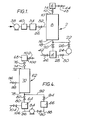
- a plant for the separation of air includes a column 2, a first reservoir 4, and a second reservoir 6.
- the column 2 and reservoirs 4 and 6 are constructed as pressure vessels.
- the column 2 contains a bed 8 of carbon molecular sieve capable of preferentially adsorbing oxygen from a gas mixture comprising oxygen and nitrogen.
- the bed 8 occupies substantially the whole internal volume of the column 2.
- the top end 10 of the bed 8 communicates with a conduit 12 which extends from the top of the column 2 to the second reservoir 6.
- a valve 14 is located in the conduit 12.
- the bottom end 16 of the bed 8 communicates with a conduit 18 which extends from the bottom of the column 2 to the first reservoir 4.
- a valve 20 is located in the conduit 18.
- a conduit 22 terminates at one end in the conduit 18 at a region thereof intermediate the valve 20 and the bottom of the column 2 and at its other end in the inlet to a pump 24.
- a valve 26 is located in the conduit 22.
- a further conduit 28 extends from the outlet of the pump 24 and terminates in the reservoir 4.
- a valve 30 is located in the conduit 28.
- the column 2 is also provided with an inlet 32 for compressed and dried air to be separated. Such air is supplied from a third reservoir 34.
- the reservoir 34 is constructed as a pressure vessel.
- the outlet of the reservoir 34 communicates with the inlet 32 and is provided with a valve 36.
- the inlet of the reservoir 34 communicates with the outlet of air compressor 38 via conventional means for removing water, particulates and carbon dioxide located at 40.
- the reservoirs 4 and 6 are provided with outlets 42 and 44 respectively having valves 46 and 48 respectively disposed therein.
- valves may be pneumatically or hydraulically operated and the relative timings of their opening and closing may be effected by means of a central programmable controller (not shown) of a kind conventional in the art.
- valve 14 is opened and gas thus flows from the bed 8 into the reservoir 6.
- the continuing flow of gas into the bed 8 from the reservoir 4 approximately balances the flow of gas out of the bed 8 into the reservoir 6 so that the pressure in the bed 8 increases only slightly during the time that the valve 14 is open.
- there is an upward translation or displacement of unadsorbed gas but the oxygen that has been previously adsorbed during the previous compression step remains adsorbed. There is thus a net upward displacement of nitrogen relative to oxygen during the compression and upward translation steps.
- nitrogen is withdrawn from the reservoir 6 via the outlet 44.
- valve 48 is opened and nitrogen is allowed to flow under pressure from the reservoir 6 to a suitable collection vessel (not shown). Typically the withdrawal of nitrogen product takes place during the latter half of the upward displacement step.
- the upward translation step continues until the pressures in the reservoirs 4 and 6 and the bed 8 become equal with one another.
- Valves 14, 20 and 44 close and valves 26 and 30 open so as to start a pressure reduction step.
- the pump 24 is operated to withdraw gas from the bottom of bed 8 and to pass it into the reservoir 4.
- the pressure in the bed 8 thus falls causing some oxygen molecules to be desorbed from the adsorbent and then to flow downwards through the bed 8. There is thus a net downward flow of oxygen.
- the gas in the voids spaces at the start of the pressure reduction step flows downwards during this step by a distance which is less than that which would be expected from a mere consideration of the pressure obtaining at the start of this step and the pressure obtaining at the end of this step.
- the duration of the pressure reduction step is typically arranged to be equal to the duration of the pressure raising or compression step.
- Change over from pressure reduction to isobaric downward translation of gas in the void spaces of the bed 8 is effected by opening valve 14. It is to be appreciated that during the pressure reduction step a pressure difference between the reservoir 6 and the bed 8 is built up.
- the downward translation step there is a downward flow of oxygen molecules previously desorbed during the pressure reduction step.
- the valve 14 When the pressure in the reservoir 6 reaches equality with that in the void spaces of the bed, the valve 14 is closed and the valve 36 opens to admit compressed dry air which is free of carbon dioxide into the bed 8 at an intermediate level.
- the pressure of the incoming air may be selected to be a little in excess of the pressure that obtains at the instant the valve 14 is closed and the valve 36 opens. It is thus possible to maintain a pressure in the bed 8 that deviates only slightly from a constant value even though gas continues to be withdrawn therefrom by the pump 24. For at least a part of the period in which air is admitted to the bed oxygen product is withdrawn from the reservoir 4.
- the valve 46 is opened and the reservoir 4 placed in communication with for example a storage vessel for product oxygen (not shown).
- the volumes of nitrogen product and oxygen product withdrawn during each cycle are equal to the volume of air admitted during each cycle.
- the ratio of volume of nitrogen product to volume of oxygen product withdrawn during each cycle is arranged to approximate to the ratio of nitrogen to oxygen in the incoming air, and the reservoirs 6 and 4 have a similar volume ratio.
- each downward displacement step and the following air admission step is typically arranged to be equal to the duration of each upward displacement step.
- the pressure of the bed 8 at the end of the air feed step equals that at the start of the preceding pressure raising or compression step.
- valves 26, 30, 36 and 46 are closed; and the valve 20 is simultaneously opened to commence the next pressure raising or compression step.
- the above described cycle of steps may be continuously repeated.
- the previously adsorbed oxygen molecules are desorbed and thus enter the void spaces of the bed at the positions where they were initially adsorbed.
- the desorbed oxygen molecules limit the downward displacement of the previously unadsorbed portion of the air band to a small extent so that the downward flow of unadsorbed gas molecules during the expansion step does not quite match the upward displacement of unadsorbed gas molecules during the previous compression step.
- the downward displacement step then takes place, during which step the air band now relatively rich in oxygen at its lower front flows downwards. There is thus a net downward flow of oxygen molecules and a net upward flow of nitrogen molecules.
- the incoming air band has been re-ordered so that it no longer contains uniform concentrations of oxygen and nitrogen but instead has a greater concentration of oxygen molecules towards its lower "fringe” and a greater concentration of nitrogen molecules towards its upper “fringe”.
- the initial "band” has become spread with the upper fringe of the band (which is relatively rich in nitrogen) being situated above the level of the inlet 32 by a distance corresponding to the extent of upward flow or displacement, and the lower "fringe" of the band having been displaced downwards by a distance corresponding to the extent of the downward flow in the cycle. It can thus be seen that in one operating cycle there has been a downward flow of oxygen molecules and an upward flow of nitrogen molecules.
- the "pressure swing" between the pressure at the start and end of the compression step is small and the volume of gas entering or leaving the bed to and from the reservoirs to be only a small increment of the total volume of the bed.
- the degree of enrichment achieved by one operating cycle may be small, and the "pressure swing" small, say a few psi, by allowing each increment of gas admitted to the bed to be in effect subjected to a multiplicity of operating cycles (typically more than ten), nitrogen and oxygen products of acceptable commercial purity may be produced by the method according to the invention.
- the invention is a radical departure in the art as prior processes have relied upon only one or a few operating cycles to effect separation.
- the operating pressure will typically be chosen in accordance with the desired product pressure, typically 2 to 4 bars.
- the invention is not limited to the use of carbon molecular sieve.
- a zeolite which is suitable for separation of nitrogen- oxygen mixtures and which adsorbs nitrogen in preference to oxygen is employed. Then, nitrogen-enriched air is collected at the bottom of the bed and oxygen-enriched air is collected at the top of the bed.
- the two columns 2(a) and 2(b) share a common source of compressed and purified air, as described with reference to Figure 1.
- the bed 8(a) is being subjected to the compression step
- the bed 8(b) is being subjected to the expansion or pressure reduction step, and vice versa.
- the bed 8(b) is subjected to the downward translation step and air feed steps, and vice versa. It is therefore necessary for each compression step to have the same duration as each pressure reduction step and for each upward translation step to have the same duration as each combined downward translation and air feed step so as to avoid discontinuous use of the pump, although such use may be reduced by means of a suitable buffer.
- the pump 24 has two inlet conduits 22(a) and 22(b) respectively and two outlet conduits 28(a) and 28(b) respectively.
- the pump 24 withdraws gas from the bed 8(a) and passes it to the reservoir 4(a) during the downward translation and air feed steps performed using the bed 8(a), and once the air feed step has ended the pump then withdraws gas from the bed 8(b) and passes it to the reservoir 4(b) during the downward translation and air feed steps performed using the bed 8(b).
- the pump is able to be used continuously.
- the plant shown in Figure 4 is generally similar to that shown in Figure 1 save that a different arrangement is employed to withdraw gas from the bottom of the adsorption bed and to return it to the bed.
- a key feature of this different arrangement is that a vacuum pump such as a Roots blower is employed to subject the adsorption bed to a vacuum during the downward translation and air feed steps.
- the plant shown in Figure 4 has a vertical column 62, reservoirs 64 and 66 associated with the lower end of the column 62 and a reservoir 68 associated with the upper end of the column 62.
- the column 62 contains a bed 70 of carbon molecular sieve capable of preferentially adsorbing oxygen from a gas mixture comprising oxygen and nitrogen.
- the bed 70 occupies substantially the whole internal volume of the column 62.
- the top end 72 of the bed 68 communicates with a conduit 74 which extends from the top of the column 62 to the reservoir 68.
- a valve 76 is located in the conduit 70.
- the bottom end 78 of the bed 70 communicates with a conduit 80 which extends from the bottom 78 of the column 62 to the top of a reservoir 64.
- a valve 82 is located in the conduit 80.
- the bottom of the reservoir 64 is connected to the inlet of a Roots blower 84 by a conduit 86.
- the outlet of the Roots blower 84 is connected by a conduit 88 to the lower end of the reservoir 66.
- a valve 90 is located in the conduit 88.
- a conduit 92 extends from the upper end of the reservoir 64 and terminates in the conduit 80 intermediate the valve 82 and the column 62.
- the valve 94 is located in the conduit 92.
- the column 62 is also provided with an inlet 96 for compressed, purified air.
- the air may be compressed and purified by conventional plant, for example, of the kind shown in Figure 1 for this purpose.
- the inlet 96 is provided with a valve 98.
- the reservoir 68 is provided with an outlet 100 having a valve 102 disposed therein and the reservoir 66 is provided with an outlet 104 having a valve 106 disposed therein.
- valves may be pneumatically or hydraulically operated and the relative timings of their opening and closing may be effected by a central programmable controller (not shown) of a kind conventional in the art.
- the pressure raising step is carried out with all valves closed save the valve 94 so that gas flows from the reservoir 66 through the conduit 92 into the bed 70.
- the upward translation step is initiated by opening the valve 76 and allowing gas to flow into the reservoir 68 from the bed 70 and thereby maintaining isobaric conditions in the bed 70.
- Product nitrogen is withdrawn during this step through outlet 100 and the valve 102 is opened to enable such withdrawal to take place.
- the pressure reduction step is initiated by opening valves 82 and 90 (simultaneously with the closing of valves 94 and 74) and operating the Roots blower 84 so as to withdraw gas from the bed 70 via the reservoir 64 and to pass this gas to the reservoir 66.
- the downward translation step commences with the opening of valve 76.
- the valve 76 closes and valve 98 opens to admit air (free of carbon dioxide and water vapour) into the bed.
- the valve 106 is opened and product oxygen is withdrawn.
- the cycle of operations is performed repeatedly.
Landscapes
- Chemical & Material Sciences (AREA)
- Engineering & Computer Science (AREA)
- Analytical Chemistry (AREA)
- General Chemical & Material Sciences (AREA)
- Oil, Petroleum & Natural Gas (AREA)
- Chemical Kinetics & Catalysis (AREA)
- Separation Of Gases By Adsorption (AREA)
Applications Claiming Priority (4)
| Application Number | Priority Date | Filing Date | Title |
|---|---|---|---|
| GB8511128 | 1985-05-02 | ||
| GB858511128A GB8511128D0 (en) | 1985-05-02 | 1985-05-02 | Separation of gas mixture |
| GB8512270 | 1985-05-15 | ||
| GB858512270A GB8512270D0 (en) | 1985-05-02 | 1985-05-15 | Separation of gas mixture |
Publications (3)
| Publication Number | Publication Date |
|---|---|
| EP0201235A2 true EP0201235A2 (fr) | 1986-11-12 |
| EP0201235A3 EP0201235A3 (en) | 1986-12-30 |
| EP0201235B1 EP0201235B1 (fr) | 1989-03-01 |
Family
ID=26289198
Family Applications (1)
| Application Number | Title | Priority Date | Filing Date |
|---|---|---|---|
| EP19860302963 Expired EP0201235B1 (fr) | 1985-05-02 | 1986-04-21 | Séparation d'un mélange gazeux |
Country Status (4)
| Country | Link |
|---|---|
| EP (1) | EP0201235B1 (fr) |
| JP (1) | JPH088971B2 (fr) |
| AU (1) | AU587028B2 (fr) |
| DE (1) | DE3662172D1 (fr) |
Cited By (4)
| Publication number | Priority date | Publication date | Assignee | Title |
|---|---|---|---|---|
| EP0483670A1 (fr) * | 1990-10-25 | 1992-05-06 | Praxair Technology, Inc. | Procédé d'adsorption en duplex |
| EP0716874A3 (fr) * | 1994-12-13 | 1996-12-11 | Boc Group Plc | Récupération de solvants |
| CN111634886A (zh) * | 2020-05-29 | 2020-09-08 | 珠海和佳医疗设备股份有限公司 | 一种吸附真空解吸制氧设备及方法 |
| US11083990B2 (en) | 2017-01-19 | 2021-08-10 | Jfe Steel Corporation | Gas separation and recovery method and facility |
Families Citing this family (2)
| Publication number | Priority date | Publication date | Assignee | Title |
|---|---|---|---|---|
| JP4900988B2 (ja) * | 2000-03-27 | 2012-03-21 | 大陽日酸株式会社 | 窒素ガス分離方法 |
| JP5256252B2 (ja) * | 2010-07-09 | 2013-08-07 | 月島環境エンジニアリング株式会社 | ガス処理方法およびガス処理設備 |
Family Cites Families (3)
| Publication number | Priority date | Publication date | Assignee | Title |
|---|---|---|---|---|
| US3149934A (en) * | 1961-07-13 | 1964-09-22 | Exxon Research Engineering Co | Cyclic adsorption process |
| US4011065A (en) * | 1974-01-09 | 1977-03-08 | Bergwerksverband Gmbh | Process for the enrichment of gases |
| US4354859A (en) * | 1981-08-06 | 1982-10-19 | Union Carbide Corporation | Enhanced gas separation by selective adsorption |
-
1986
- 1986-04-21 EP EP19860302963 patent/EP0201235B1/fr not_active Expired
- 1986-04-21 DE DE8686302963T patent/DE3662172D1/de not_active Expired
- 1986-05-01 AU AU56895/86A patent/AU587028B2/en not_active Ceased
- 1986-05-01 JP JP61101900A patent/JPH088971B2/ja not_active Expired - Lifetime
Cited By (4)
| Publication number | Priority date | Publication date | Assignee | Title |
|---|---|---|---|---|
| EP0483670A1 (fr) * | 1990-10-25 | 1992-05-06 | Praxair Technology, Inc. | Procédé d'adsorption en duplex |
| EP0716874A3 (fr) * | 1994-12-13 | 1996-12-11 | Boc Group Plc | Récupération de solvants |
| US11083990B2 (en) | 2017-01-19 | 2021-08-10 | Jfe Steel Corporation | Gas separation and recovery method and facility |
| CN111634886A (zh) * | 2020-05-29 | 2020-09-08 | 珠海和佳医疗设备股份有限公司 | 一种吸附真空解吸制氧设备及方法 |
Also Published As
| Publication number | Publication date |
|---|---|
| EP0201235B1 (fr) | 1989-03-01 |
| AU5689586A (en) | 1986-11-06 |
| AU587028B2 (en) | 1989-08-03 |
| DE3662172D1 (en) | 1989-04-06 |
| JPH088971B2 (ja) | 1996-01-31 |
| JPS61254218A (ja) | 1986-11-12 |
| EP0201235A3 (en) | 1986-12-30 |
Similar Documents
| Publication | Publication Date | Title |
|---|---|---|
| US4144037A (en) | Gas separation | |
| CA1099925A (fr) | Epuration de l'hydrogene par adsorption selective | |
| KR100254295B1 (ko) | 단일 흡착 베드를 이용한 압력 스윙 흡착 방법 | |
| US4781735A (en) | Enrichment in oxygen gas | |
| US5223004A (en) | Method for producing oxygen by adsorption separation from air | |
| EP0462778B1 (fr) | Procédé d'adsorption à pression alternée pour la séparation de mélanges gazeux | |
| US4614525A (en) | Pressure swing process for the adsorptive separation of gaseous mixtures | |
| JP2650738B2 (ja) | 水素を含むガス混合物の分離 | |
| US5702504A (en) | Vacuum pressure swing adsorption process | |
| US5137549A (en) | Two stage super-enriched oxygen concentrator | |
| EP0486926A1 (fr) | Séparation de gaz par adsorption rapide à pression alternée | |
| EP0327732A1 (fr) | Séparation par adsorption en utilisant plusieurs lits d'adsorption | |
| KR100436111B1 (ko) | 흡착제베드의상층및바닥의동시진공화를이용한압력순환흡착식방법및시스템 | |
| EP0714690A2 (fr) | Procédé d'adsorption à pression alternée | |
| JPS6325809B2 (fr) | ||
| KR880000128A (ko) | 흡착에 의한 기체 혼합물의 분리 방법 | |
| US6527830B1 (en) | Pressure swing adsorption process for co-producing nitrogen and oxygen | |
| KR20080066973A (ko) | 산소 생산을 위한 압력 스윙 흡착 방법 | |
| JP2000157828A (ja) | 1つの吸着器と1つのブロワ―を使用する酸素製造方法及び装置 | |
| CN85103557A (zh) | 变压吸附法富集煤矿瓦斯气中甲烷 | |
| JPH0321207B2 (fr) | ||
| US3619984A (en) | Gas separation by adsorption | |
| US3242645A (en) | Process for separating a binary gas mixture by contact with an adsorbent | |
| EP0201235B1 (fr) | Séparation d'un mélange gazeux | |
| EP0219103A2 (fr) | Oxydation de matière carbonifère |
Legal Events
| Date | Code | Title | Description |
|---|---|---|---|
| PUAI | Public reference made under article 153(3) epc to a published international application that has entered the european phase |
Free format text: ORIGINAL CODE: 0009012 |
|
| AK | Designated contracting states |
Kind code of ref document: A2 Designated state(s): BE DE FR IT NL |
|
| PUAL | Search report despatched |
Free format text: ORIGINAL CODE: 0009013 |
|
| AK | Designated contracting states |
Kind code of ref document: A3 Designated state(s): BE DE FR IT NL |
|
| 17P | Request for examination filed |
Effective date: 19870130 |
|
| 17Q | First examination report despatched |
Effective date: 19871208 |
|
| ITF | It: translation for a ep patent filed | ||
| GRAA | (expected) grant |
Free format text: ORIGINAL CODE: 0009210 |
|
| AK | Designated contracting states |
Kind code of ref document: B1 Designated state(s): BE DE FR IT NL |
|
| REF | Corresponds to: |
Ref document number: 3662172 Country of ref document: DE Date of ref document: 19890406 |
|
| ET | Fr: translation filed | ||
| PLBE | No opposition filed within time limit |
Free format text: ORIGINAL CODE: 0009261 |
|
| STAA | Information on the status of an ep patent application or granted ep patent |
Free format text: STATUS: NO OPPOSITION FILED WITHIN TIME LIMIT |
|
| 26N | No opposition filed | ||
| ITTA | It: last paid annual fee | ||
| PGFP | Annual fee paid to national office [announced via postgrant information from national office to epo] |
Ref country code: BE Payment date: 19920325 Year of fee payment: 7 |
|
| PGFP | Annual fee paid to national office [announced via postgrant information from national office to epo] |
Ref country code: NL Payment date: 19920430 Year of fee payment: 7 |
|
| PG25 | Lapsed in a contracting state [announced via postgrant information from national office to epo] |
Ref country code: BE Effective date: 19930430 |
|
| BERE | Be: lapsed |
Owner name: THE BOC GROUP P.L.C. Effective date: 19930430 |
|
| PG25 | Lapsed in a contracting state [announced via postgrant information from national office to epo] |
Ref country code: NL Effective date: 19931101 |
|
| NLV4 | Nl: lapsed or anulled due to non-payment of the annual fee | ||
| PGFP | Annual fee paid to national office [announced via postgrant information from national office to epo] |
Ref country code: FR Payment date: 20010330 Year of fee payment: 16 |
|
| PGFP | Annual fee paid to national office [announced via postgrant information from national office to epo] |
Ref country code: DE Payment date: 20010402 Year of fee payment: 16 |
|
| PG25 | Lapsed in a contracting state [announced via postgrant information from national office to epo] |
Ref country code: DE Free format text: LAPSE BECAUSE OF NON-PAYMENT OF DUE FEES Effective date: 20021101 |
|
| PG25 | Lapsed in a contracting state [announced via postgrant information from national office to epo] |
Ref country code: FR Free format text: LAPSE BECAUSE OF NON-PAYMENT OF DUE FEES Effective date: 20021231 |
|
| REG | Reference to a national code |
Ref country code: FR Ref legal event code: ST |
|
| PG25 | Lapsed in a contracting state [announced via postgrant information from national office to epo] |
Ref country code: IT Free format text: LAPSE BECAUSE OF NON-PAYMENT OF DUE FEES;WARNING: LAPSES OF ITALIAN PATENTS WITH EFFECTIVE DATE BEFORE 2007 MAY HAVE OCCURRED AT ANY TIME BEFORE 2007. THE CORRECT EFFECTIVE DATE MAY BE DIFFERENT FROM THE ONE RECORDED. Effective date: 20050421 |