EP0201318A2 - Transsonisches Axial-Radial-Verdichtungsverfahren und -vorrichtung mit hohem Wirkungsgrad - Google Patents
Transsonisches Axial-Radial-Verdichtungsverfahren und -vorrichtung mit hohem Wirkungsgrad Download PDFInfo
- Publication number
- EP0201318A2 EP0201318A2 EP86303448A EP86303448A EP0201318A2 EP 0201318 A2 EP0201318 A2 EP 0201318A2 EP 86303448 A EP86303448 A EP 86303448A EP 86303448 A EP86303448 A EP 86303448A EP 0201318 A2 EP0201318 A2 EP 0201318A2
- Authority
- EP
- European Patent Office
- Prior art keywords
- radially
- relative velocity
- flow
- annular wall
- annular
- Prior art date
- Legal status (The legal status is an assumption and is not a legal conclusion. Google has not performed a legal analysis and makes no representation as to the accuracy of the status listed.)
- Granted
Links
Images


Classifications
-
- F—MECHANICAL ENGINEERING; LIGHTING; HEATING; WEAPONS; BLASTING
- F04—POSITIVE - DISPLACEMENT MACHINES FOR LIQUIDS; PUMPS FOR LIQUIDS OR ELASTIC FLUIDS
- F04D—NON-POSITIVE-DISPLACEMENT PUMPS
- F04D17/00—Radial-flow pumps, e.g. centrifugal pumps; Helico-centrifugal pumps
- F04D17/06—Helico-centrifugal pumps
-
- F—MECHANICAL ENGINEERING; LIGHTING; HEATING; WEAPONS; BLASTING
- F04—POSITIVE - DISPLACEMENT MACHINES FOR LIQUIDS; PUMPS FOR LIQUIDS OR ELASTIC FLUIDS
- F04D—NON-POSITIVE-DISPLACEMENT PUMPS
- F04D29/00—Details, component parts, or accessories
- F04D29/40—Casings; Connections of working fluid
- F04D29/52—Casings; Connections of working fluid for axial pumps
- F04D29/54—Fluid-guiding means, e.g. diffusers
- F04D29/541—Specially adapted for elastic fluid pumps
- F04D29/542—Bladed diffusers
- F04D29/544—Blade shapes
Definitions
- the present invention relates to a compression or pressurisation method and apparatus in particular, those of rotary continuous-flow type for use with elastic fluids such as air.
- the present invention is particularly concerned with turbomachinery compressor method and apparatus of a type having characteristics both of known axial-flow and known centrifugal-flow types, but differing quite remarkably in structure and method of operation from either of these known types. Consequently, the present invention is related in a genral way to apparatus commonly grouped under the genus of mixed-flow axial-centrifugal type. The present invention is particularly applicable to a combustiom turbine engine.
- centrifugal compressor stages in comparison with axial-flow copressor stages tend to be lower in cost and provide a higher static pressure ratio. They also tend to offer superior.resistance to damage from ingestion of foreign objects "foreign object damage" or FOD) and superior tolerance to distortion or nonuniformity of the inlet air flow distribution.
- FOD foreign object damage
- contrifugal compressors are in general slightly less efficient and have a larger outer diameter than comparable axial flow compressors.
- United States Patent 2,609,141, of G. Aue proposes a mixed-flow compressor of this type in which it is proposed that the modified channel pipe diffuser may relieve only the radially outwards, or both the radially outward and tengential components of air flow velocity leaving the rotor.
- the radially outward component of the air flow leaving this kind of rotor is of sufficient magnitude that when the modified channel pipe diffuser is configured to relieve only this radially outward component, performance of the compressor is unacceptably low by contemporary standards.
- the configuratin of the channel pipe diffuser to relieve both radial and tangential velocity components of air flow from the compressor rotor further increases the performance shortfall of such a compressor by current standards.
- a compressor according to this invention is to achieve a compressor envelope or outer diameter the same as, or only slightly larger than, that offered by the best conventional axial-flow compressor technology; to achieve a static pressure ratio, cost, inlet distortion tolerance and resistance to FOD substantially the same as that offered by the best conventional centrifugal flow compressor technology; and to achieve a compressor efficiency at least equal to that of the conventional centrifugal compressors, and preferably approaching the efficiency of conventional axial-flow compressors.
- compressor apparatus comprising a housing and a rotor, the housing comprising an axially and circur r ferentially extending annular wall having an inlet and an outlet, the rotor being jounaled within the housing and having a hub with a plurality of blades, the hub and annular wall together defining an annular axially extending passage characterised in that, the annular wall includes a portion at the inlet which is of right circular cylindrical shape in transverse section a portion at the outlet which is of right circular conical shape in transverse section and which diverges downstream relative to the inlet, and a smooth transitional intermediate portion between the cylindrical inlet portion and conical outlet portion; and in that the hub is cone-shaped and extends between the inlet and the outlet.
- Such apparatus may be considered mixed-flow transomic compressor apparatus suitable for compressible fluids.
- the blades extend axially, circumferentially and radially from the hub to a position just short of the annular wall , and conform closely to the shape of the annular wall at axial positions throughout the inlet portion, the intermediate portion and the outlet portion.
- the hub and the annular wall define a flow path for receiving a flow stream of compressible fluid having a first vector sum of meridional velocity and tangential relative velocity of at least Mach 1.2 with respect to a selected reference adjacent the inlet portion, and for diffusion the flow stream at a second supersonic relative velocity less than the first relative velocity while limiting deviation of radially outer local relative velocity vectors to no more than 10° with respect to the first relative velocity vector.
- the hub preferably defines a curvilinear cone-shaped outer surface, which is axially congruent with the housing at the inlet and outlet.
- the blades may extend circumferentially from the inlet end to the outlet end in a direction opposite to the rotational direction of the rotor and further comprise determined compressible fluid stream line shapes stacked substantially radially outwards from the hub outer surface towards the housing.
- each blade defines a radially extending leading edge, a radially extending trailing edge, and a radially, axially and circumferentially extending radially outer tip edge comforming in shape to the annular wall at the inlet portion, the intermediate portion, and the outlet portion, the tip edges considered in axial and radial aspect defining a tip edge meridional dimension for the blades, the leading edges defining a virtual intersection with the annular wall at the inlet portion and the trailing edges defining a virtual intersection with the annular wall at the outlet portion.
- the inlet portion of right circular cylindrical section extends upstream of the virtual intersection of the leading edges for a distance of from about 10% to about 20% of the tip edge meridional dimension
- the inlet portion of right circular cylindrical sectin extends downstream of the virtual intersection of the leading edges for a distance of from 10% to 30% of the tip edge meridional dimension.
- the circular section inlet portion and right circular conical section oulet portion of the annular wall are in axial section angularly disposed relative to one another so as to define an acute angle between them in the range from about 5° to about 45° preferably 22 0 .
- the leading edges may be swept downstream radially outwardly with respect to a rad ally extending line from the axis to define a leading edge sweep angle.
- the sweep angle may be in the range of substantially 0° to about 15 0 , preferably substantially 7°.
- the conical section outles portion of the annular wall extends upstream of the virtual intersection of the trailing edges for a distance of from about 10% to about 30% of the tip edge meridional dimension
- the conical section outlet pcrtion of the annular wall extends downstream of the virtual intersection of the trailing edges for a distance of from about 5% to about 15% of the tip edge meridional dimension.
- the trailing edges may be swept upstream radially outwardly with respect to a radially extending line from the axis to define a trailing edge sweep angle. This sweep angle may be in the range of substantially 0° to about 35 0 , preferably substantially 23 0 .
- the leading edges define a diameter RBi at their intersection with the hub and a diameter RBo at their intersection with the tip edges
- the trailing edges define a diameter REi at their intersection with the hub and a diameter REo at their intersection with the tip edges
- the ratio of REi to RBi being in the range from about 1.5 to about 3.5 and the ratio of REo to RBo is in the range from about 1.05 to about 1.76.
- the ratio of REi to RBi is substantially 2.75 and the ratio of REo to RBo is substantially 1.17.
- the blades define a quantity termed, average meridional blade length (AMBL), which is the length in axial and radial aspect of a line along a blade from the leading edge to the trailing edge and defined by points on the blade radially midway between the hub and the tip edge, the ratio (AR) of (RBo-RBi) + (REo-REi) to AMBL lying in the range from about 0.75 to about 1.30.
- the ratio AR is substantially 1.12.
- the blades have a height dimension at their trailing edge defined as REo-REi
- the compressor apparatus further includes a second axially and circumferentially extending annular wall disposed radially inwardly of the first annular wall and immediately downstream of the rotor, the two annular walls being radially spaced apart to define an axially extending annular flow path downstream of the rotor, the inner wall defining a first radially outwardly convex annular surface portion bounding the flow path and being arcuate of radius R in axial section, the ratio of the trailing edge blade height to the radius R lying in the range from avout 1.0 to about 4.0.
- the ratio of trailing edge blade height to radius R is substantially 2.0.
- the first annular wall defines a radially inwardly concave annular surface portion bounding the flow path downstream of the right circular conical outlet portion, the concave annular surface portion of the first annular wall cooperating with the convex annular surface portion of the second annular wall to define the flow path downstream of the rotor the flow path extending radially outwardly and axially with a substantially constant transverse sectional fluid flow area.
- the apparatus includes annular diffuser means located at or near the rotor at the outlet end which receives, via the flow path, a flow of compressible fluid having a first determined subsonic relative velocity vector sum of tagential and meridional velocity, having a respective significant radially outward component, and discharges a flow of compressible fluid having a second determined relative velocity vector having radially outward and tagential components of substantially zero (substantially pure axial flow).
- the diffuser means includes successive downstream first and second axially spaced apart annular arrays of circumferentially spaced apart diffuser vanes, in which the first diffuser vanes are arranged to receive from the outlet portion, a flow of compressible fluid having the first determined relative velocity vector, and to diffuse the fluid flow to discharge into an axially extending interdiffuser space, a flow of the fluid having a second determined relative velocity vector less than the first relative velocity vector and having a radially outward component of substantially zero, and in which the second diffuser vanes are arranged to receive from the interdiffuser space the flow of fluid having the second determined relative velocity vector and to diffuse the latter to discharge a flow of the fluid having a third determined relative velocity vector less than the second relative velocity vector and having both tangential and radially outward components of substantially zero.
- the annular wall may define a second right circular cylindrical portion radially outwardly bounding the flow path downstream of the concave annular surface portion, and a first annular array of plural radially extending diffuser vanes may extend between the convex annular surface portion and-annular wall, the diffuser vanes each having a leading edge with respect to the fluid flow.
- the leading edges of the first array of diffuser vanes may intersect the annular wall downstream of the concave annular surface portion of the annular wall.
- the leading edges of the first annular array of diffuser vanes may be swept downstream radially outwardly with respect to a radial line from the axis.
- the other annular wall may define a third right circular cylindrical portion spaced radially inwardly of the second right circular cylindrical portion and may radially inwardly bound the flow path downstream of the convex annular surface portion and a second annular array of radially extending diffuser vanes may extend between the second and third right circular cylindrical wall portions.
- the first annular array of diffuser vanes may each include a trailing edge spaced axially downstream of the leading edge, the leading edges and trailing edges cooperating to define a chord dimension for the first annular array of diffuser vanes, the second annular array of diffuser vanes being spaced axially downstream of the first array by substantially one-half of the chord dimension.
- a first axially ending radially outer annular wall having first to fifth portions arranged sequentially downstream with respect to a fluid flow through the compressor, the first wall portion defining a compressor inlet and inwardly being of right circular cylindrical shape in transverse section, the second wall portion being radially inwardly convex to transition between the first wall portion and the third wall portion, the third wall portion being inwardly of right circular conical shape and diverging downstream in transverse section, the fourth wall portion being radially inwardly concave to transition between the third wall portion and the fifth wall portion and defining an annular fluid flow path in cooperation with a second radially inner annular wall, the fifth wall portion being inwardly of right circular cylindrical shape in transverse section; the second radially inner annular wall being disposed downstream of the inlet in substantial radial juxtaposition with the fourth and fifth portions of the radially outer wall to define a rotor chamber in juxtaposition with the first to third wall portions, the second wall having portions
- a transonic mixed flow compressor comprising a housing defining an inlet portion an outlet portion, and an axially extending flow path extending therebetween for flow of the elastic fluid; a rotor journaled in the flow path for rotation about the axis and having a respective inlet end and oulet end, the housing and rotor defining cooperating means for defining an annular stream tube extending axially from the inlet towards the outlet in the flow path and diverging downstream radially outwardly to define at a radially outer boundary thereof upstream of the rotor outlet end substantially a right circular conical section.
- a method of pressurising an elastic fluid comprising the steps of : forming a tubular stream of the fluid having a radially inner diameter, a radially outer diameter, and a first relative velocity vector sum of meridional and tangential velocities of at least Mach 1.2 at the radially outer diameter; diffusing the fluid to a second supersonic relative velocity less than the first relative velocity while limiting deviation of radially outer local relative velocity vectors to no more than 10° with respect to the first relative velocity vector; passing the fluid through a normal shock to a third relative velocity of less than Mach 1; and further diffusing the fluid stream while increasing downstream both the radially inner and radially outer diameters thereof to impart a significant radially outward component of meridional velocity thereto.
- a method of compressing elastic fluid comprising the steps of forming a rotational annulus of axially flowing fluid fluid having an inner diameter, an outer diameter, and a first relative velocity vector sum of meridional and tangential velocities of less than Mach 1; diffusing the flowing fluid to a second relative velocity less than the first relative velocity while increasing progressively downstream the outer diameter and increasing the radially outward component of the meridional velocity; holding the increase of the outer diameter to a constant axial rate while further diffusing the flowing fluid to a third relative velocity less than that of the second relative velocity while decreasing the radially outward component of the meridional velocity to a value less than that of the second relative velocity.
- the invention may therefore extend to a method of pressurising elastic fluid to increase its pressure level from a first pressure level to a higher second pressure level, the method comprising the steps of: forming a first tubular stream of the fluid at the first pressure level, having a longitudinal axis, a first radially inner diameter, a first radially outer diameter, and a first relative velocity vector sum of meridional velocity and tangential velocity of at least Mach 1.2 with respect to a selected reference at the radially outer diameter; subdividing the flow stream into a plurality of axially extending and circumferentially spaced apart substreams; diffusing each of the substreams to a second supersonic relative velocity less than the first relative velocity while limiting deviation of radially outer local relative velocity vectors to no more than 10° with respect to the first relative velocity vector; passing each of the substreams through a respective normal shock to a third relative velocity of less than Mach 1; increasing progressively downstream for the normal shock both the radially inner and radially outer diameters of the flow
- Such a method may include the further steps of subdividing the second tubular stream into a second plurality of axially extending and circumferentially spaced apart substreams each having substantially the sixth absolute velocity vector sum of tangential and meridional velocities, the latter of which includes a radially outward component of a seventh value; diffusing each of the second substreams to an eighth absolute velocity vector sum of tangential and meridional velocities having a tangential component less than that of the sixth vector sum and a radial component of substantially zero; and reuniting the second plurality of substreams into a respective third tubular stream of the fluid having the eighth subsonic absolute velocity vector sum or meridional and tengential velocities.
- the method may also include the further steps of : subdividing the third tubular stream into a third plurality of axially extending and circumferentially spaced apart substreams each having substantially the eight absolute velocity vector sum or meridional and tangential velocities; diffusing each of the third substreams to a ninth absolute velocity vector sum of meridional and tangential velocities having a tangential component of substantially zero while maintaining a radial velocity component of substantially zero; and reuniting the third plurality of substreams into a respective fourth tubular stream of the fluid having the ninth subsonic absolute velocity vector sum of meridional and tangential velocities having both radial and tangential components of substantially zero (substantially pure axial flow).
- the invention may also extend to a method of diffusing an annulus of flowing elastic fluid having a first absolute velocity and respective first tangential and radially outward components of velocity, the method comprising the steps of : subdividing the annulus into a plurality of radially outwardly and axially extending circumferentially spaced apart substreams each having substantially the first tangential and radially outward components of velocity; diffusing each of the plurality of substreams to a second absolute velocity less than the first absolute velocity and having a respective axial velocity, a respective tangential velocity significantly less than the first tangential velocity, and a respective radially outward velocity component in the range of substantially zero to a negative value; and reuniting the plurality of substreams into a second annuls of flowing fluid having the second absolute velocity, the second axial velocity component, the second tangential component of velocity, and the second radially outward component of velocity.
- This latter method may include the further steps of subdividing the second annulus into a second plurality of axially extending and circumferentially spaced apart substreams each having substantially the second absolute velocity, the second axial velocity component, the second tangential velocity component, and the second radially outward velocity component; diffusing each of the substreams to a third absolute velocity less than the second absolute velocity, and having a respective axial velocity component, a respective tangential velocity component of substantially zero, and a respective radial velocity component of substantially zero; and reuniting the third plurlity of substreams into a third annulus of flowing fluid having the third absolute velocity including the third axial velocity component, the third tangential velocity component of substantially zero, and teh third radial velocity component of substantially zero (substantially pure axial flow).
- This invention also encompasses a jet propulsion engine incorporating a compressor method and/or apparatus as described above. It will be appreciated that the present invention may substantially satisfy each of the obectives outlined above and by doing so may provide the highly desirable advantages resulting therefrom. Additionally, the applicants have found that the compressor provided, because its diffuser structure presents a diffuser flow path defined between coannular right circular cylindrical wall sections, affords a structure of greater strength for a particular weight than either conventional centrifugal or mixed-flow diffuser structures.
- the flowpath 24 Downstream of the diffuser 26, the flowpath 24 is bifurcated into an outer annular flowpath passage 28, and an inner annular core engine flowpath 30.
- the flowpath 28 communicates directly downstream with a tailpipe portion 32 of the engine 10 and the tailpipe portion communicates with the outlet opening 16. Accordingly, it will be appreciated that the compressor rotor 22 serves also in the capacity of a fan with respect to the turbofan nature of the engine 10.
- the core engine flowpath 30 proceeds downstream through a two-stage axial flow compressor section 34, having two axially spaced apart blade wheels drivingly carried by the shaft 18.
- the flowpath 30 subsequently extends through an annular combustor 36, and through the turbine section 20.
- the turbine section 20 also communicates with the tailpipe portion 32 and with the outlet opening 16.
- FIG 2 this illustrates that the compressor rotor 22 includes a hub portion 38, which reference to Figures 1 and 3 will show defines an outer surface 40 of elongate conical shape.
- a hub portion 38 Disposed upon the hub 38 and extending radially outwardly thereon is a plurality of axially and circumferentially extending blades 42.
- there are seventeen blades 42 which are equiangularly circumferentially spaced apart.
- Each blade 42 defines a radially extending leading edge 44, a radially extending trailing edge 46, and a radially outer axially and radially extending tip edge 48.
- the blades 42 extend radially outwardly towards a wall portion 50 of the housing 12 and terminate in the radially outer tip edges 48 which are spaced slightly radially inwardly of the radially inner surface 52 of the wall portion 50 and have a shape conforming to that of the inner surface 52.
- the wall portion 50 extends continuously axially and circumerentially from the inlet opening 16 downstream past the compressor rotor 22, the flow path 24, and the diffuser section 26. Beginning at inlet opening 16 and continuing downstream (to the right in Figure 3) at a selected distance therefrom, the wall portion 50 defines a radially inner surface subsection 52a in the shape of a right circular cylindrical surface.
- the right circular cylindrical surface portion 52a of wall 50 extends downstream beyond the leading edges 44 of the blades 42.
- the wall portion 50 adjacent the trailing edges 46 and extending certain distances both upstream and downstream of the virtual intersection of the trailing edges with the wall surface 52 defines a radially inner surface subsection 52b in the shape of a truncated right circular conical surface. Between the right circular cylindrical subsection 52a of the wall 50 and the right circular conical subsection 52b, the wall portion 50 defines an axially curvilinear radially inner transition surface subsection 52c which is radially inwardly convex. In other words, between the leading edges 44 and the trailing edges 46 of the blades 42, the wall 50 defines a subsection 52c which is an axially curvilinear transition surface of revolution, and which avoids a defined cusp between the cylindrical and conical subsection 52a and 52b. It is significant that the curvilinear transition subsection 52c does not extend to the trailing edges 46, and in fact joins the subsection 52b some distance upstream of these trailing edges.
- the right circular cylindrical surface 52a As shown in Figures 3 and 4, upstream of the virtual instersection of the leading edges 44 with the wall 50 (figure 4, point B) and extending downstream thereto, the right circular cylindrical surface 52a has an axial dimension of from about 10% to about 20% of the meridional dimension of the blades 42 at their tip edges 48 ( Figure 4, A-B dimension). Similarly, extending downstream from the virtual instersection of the leading edges 44 with the wall 50 (Figure 4, point B), the right circular cylindrical surface 52a has an axial dimension of from about 10% to about 30% of the meridional dimension of the blades 42 at their tip edges 48 (Figure 4, B-C dimension).
- the right conical surface portion 52b Adjacent the virtual intersection of the trailing edges 46 with the wall 50 (Figure 4, point E), the right conical surface portion 52b extends both upstream and downstream.
- the downstream meridional extension of the surface 52b is from about 5% to about 15% of the meridional length of the blades 42 at their tip edges 48.
- the upstream meridional extension of the surface 52b from the point E is from about 10% to about 30% of the meridional dimension of the blades 42 at their edges 48 ( Figure 4, D-E dimension). Consequently, the transition surface subsection 52c defines from about 40% to about 80% of the meridional dimension of the blades 42 at their edges 48.
- the flowpath coextensive with the rotor 22 is radially outwardly bounded by the surfaces 52a and 52b defining two relatively inclined axially extending straight line segments.
- the straight line segments of the surfaces 52a and 52b are jointed by a continuous, smooth, nonlinear curved surface section 52c which is tangential to both of the straight line surface sections.
- the surfaces 52a and 52b define an acute angle (referenced with numeral 54) of about 22° with respect to one another.
- the angle 54 may be from about 5° to about 45 0 .
- leading edges 44 of the blades 42 are swept downstream radially outwardly with respect to a radially extending line 56 perpendicular to the rotational axis of the rotor 22.
- the leading edges 44 define an acute angle 58 of about 7°.
- the angle 58 may be from about 0° to about 15 0 .
- the trailing edges 46 are swept upstream radially outwardly with respect to a radially extending line 60 perpendicular to the rotational axis of the rotor 22.
- the trailing edges 46 define an acute angle 62 of about 23 0 .
- the angle 62 may, however, be from 0° to about 35 0 .
- a radius dimension RBi is defined at the intersection of the leading edge 44 with the outer surface of the hub 38.
- a radius dimension REi is defined at the intersection of the trailing edge 46 with the surface 40.
- the ratio of REi to RBi is about 2.75. However, this ratio may permissibly vary between about 1.5 and 3.5.
- a relatively small ratio of outer radius change of the rotor 22 from leading edge to trailing edge of blades 42 should be employed.
- a radius dimension RBo is defined at the virtual intersection of the leading edge 44 with the surface 52.
- a radius dimension REo is similarly defined at the virtual intersection of the trailing edge 46 with the surface 52.
- the ratio of REo to RBo is preferably 1.17, however, this ratio may very from about 1.05 to about 1.76.
- this relatively low ratio of radius increase from inlet to outlet of the rotor 22 contributes to the relatively small overall diameter which is possible in a compressor according to the invention, in comparison to its inlet diameter.
- a further geometric aspect of the rotor 22 which is considered of importance by the applicants is a dimensionless ratio termed the Aspect Ratio (AR), defined below:-
- the average meridional blade length of blades 42 is depicted on Figure 4 as line 64, which is generated by those points on the blade lying radially midway between the surface 40 and the tip edge 48.
- the ratio AR is 1.12. This ratio may, however, vary between about 0.75 and 1.30.
- the housing 12 Downstream of the trailing edges 46, the housing 12 defines annular fluid flow path 24 between the radially outer wall 50 and an annular radially inner wall 65 which is spaced radially inwardly of the wall 50 and has a radially outwardly disposed surface portion 66a.
- the surface 66 is a curvilinear surface of revolution having a radius 68 originating from a centre point 70.
- the radius 68 is related to the height of the blades 42 at the trailing edge 46 in that the radial distance along the trailing edge 46 from its intersection with the surface 40 of hub 38 to its virtual intersection with surface 52 is considered the blade height at the trailing edges of the blades 46.
- the ratio of the radius 68 to the blade height at the trailing edge 46 is preferably 2.0, however, this ratio may vary from about 1.0 to about 4.0.
- the flow path 24 is circumferentially continuous between the walls 50 and 65.
- the radially outer wall 50 defines a surface portion 52d which is a curvilinear surface of revolution tangent at its upstream end with the right circular conical surface portion 52c.
- the radius of the wall surface 52d is matched so that of the surface portion 66a so that a flow path portion 24a is defined which is of substantially constant area despite the radius change in the flow path with respect to the rotational.axis of the rotor 22.
- the surface portion 52d is also tangent with a right circular cylindrical surface portion 52e of the wall 50.
- the wall 65 defines a radially outwardly disposed right circular cylindrical surface portion 66b which at its upstream end is tangent with the surface portion 66a of the wall 65.
- an annular array of radially extending and circumferentially spaced apart diffuser vanes 72 extend between the walls 50 and 65 in the region of the surface portions 52e and 66a thereof, respectively.
- the vanes 72 each define a leading edge 74, and a trailing edge 76. While it will be noted that at their radially inner ends, the vanes 72 are relatively close to the trailing edge 46 of the compressor blades 42 and intersect the curvilinear surface portion 66a, the radially outer ends of the vanes 72 intersect the cylindrical surface portion 52e. Thus, the diffuser vanes are swept downstream radially outwardly to intersect the radially outer wall 50 at the cylindrical portion 52e.
- each vane 72 intersects the wall 50 down stream of the curvilinear surface portion 52d. That is, the vanes 74 at their radially outer ends intersect the right circular cylindrical portion of the wall 50 at the surface 52e. It will be noted that the vanes 74 are swept downstream radially outwardly with respect to a radial perpendicular from the rotational axis of the rotor 22. The physical sweep angle is in the range of from zero degrees to twenty-five degrees. However, the vanes 74 are swept to an even greater aerodynamic degree with respect to the air flow from the rotor 22. This is due to the combination of axial and radially outward velocity components of this air flow, as will be explained more fully below.
- the flow path 24 Downstream of the trailing edges 76 of the diffuser vanes 72, the flow path 24 is once again circumferentially continuous to define a vane-wake dissipation area 24b. Since the surfaces 52e and 66b are right circular cylindrical surface sections, it will be appreciated that the flow path portion 24b is of constant cross sectional flow area. As a result, substantially no flow diffusion occurs within the portion 24b.
- the diffuser 26 Downstream of the diffuser vanes 72, and spaced axially therefrom by approximately one-half a cord dimension of the latter, the diffuser 26 also includes a second annular array of radially extendin+g and circumferentially spaced apart diffuser vanes 78.
- the diffuser vanes 78 include leading edges 80 and trailing edges 82 which are swept with respect to a radial perpendicular from the rotational axis of rotor 22.
- the geometric sweep of the vanes 72 closely approximates to their aerodynamic sweep angle because the air flow traversing these diffuser vanes has little or no radial velocity component.
- the turbine section 20 drives the shaft 18 at a high speed of rotation, and the shaft 18 drives the compressor rotor 22.
- the wall 50 defining the surface portion 52a of the housing 12 cooperates with the axially extending conical nose portion 38a of the hub 38 to define an axially extending annular passage 24'.
- ambient air is drawn through the passage 24', as shown by arrow 84. Consequently, it will be seen that the passage 24' defines an axially extending annular flow stream of axially flowing air 84.
- the annular flow stream of air 84 is subdivided into substreams which are circumferentially spaced apart by the blades 42.
- the leading edges 44 have a tangential velocity vector (Vt) referenced with numeral 86. Consequently, air flow 84 approaching the blades 42 has a negative relative tangential velocity vector of -Vt, which is referenced by numeral 88.
- the air flow 84 adjacent the tip edges 48 also has a meridional component of relative velocity represented by vector (Vm) and referenced with numeral 90.
- Meridional velocity as used herein is the vector sum of axial and radial airflow velocity components.
- the air flow 84 has a relative velocity vector sum of Vt and Vm which is represented by vector Vr, and referenced with number 92.
- the meridional relative velocity vector Vm includes also any radial relative velocity component (VR) between the blades 42 and the air flow 84.
- VR radial relative velocity component
- the outward radial velocity of the air flow 84 must be zero, or substantially zero because the wall surface 52a is of right circular cylindrical shape.
- the relative velocity vector 92 (Vr) has a magnitude of at least Mach 1.2, and is preferably in the range of Mach 1.3 to 1.5, or higher.
- the leading edge 44 of each blade 42 is believed to originate a Mach wave 94.
- the surface of the blades 42 extending downstream of the leading edge 44 and facing in a tangential direction opposite to the rotational direction of the rotor 22 is shaped according to known aerodynamic principles to originate multiple additional Mach waves, which, as depicted, are two in number and are referenced with numerals 96, 98. It will be understood that the number of additional Mach waves may be other than two.
- one of the Mach waves encounters the next circumferentially adjacent blade 42 opposite to the direction of rotation of the rotor 22 at or downstream of its leading edge 44.
- the wave 98 becomes a captured Mach wave.
- an oblique shock wave 100 is believed to originate and to extend toward the next circumferentially adjacent blade 42 in the direction of rotation of the rotor 22.
- a normal shock 102 is believed to be formed downstream of oblique shock 100.
- Each of the Mach waves 94, 96, 98, the oblique shock 100 and the normal shock 102 is believed to effect a diffusion or slowing of the flow of air 84 relative to blades 42, and a concomitant increase of total pressure of the airflow.
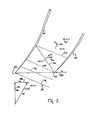
- notations have been placed upon Figure 5 which are generally indicative of the relative velocity of the airflow field at the location of the particular notation.
- the airflow 84 approaches the rotor 22 as an axially flowing annular stream tube having a relative velocity of at least Mach 1.2. (Figure 5, M»1) represented by the vector 92 (Vr).
- Figure 5, M the airflow is weakly diffused through successive Mach waves 94-98, the last of which is a captured Mach wave preceding a stronger oblique shock 100.
- the air flow Upstream of the oblique shock 100, the air flow has a relative velocity vector 104 which is supersonic (Figure 5, M»1), but less in magnitude than velocity vector 92.
- the airflow has a relative velocity which is greater than Mach 1, (Figure 5, M>1), but less than the velocity upstream of the shock 100.
- the airflow Immediately downstream of the normal shock 102, the airflow has a relative velocity less than Mach 1 (Figure 5, M ⁇ 1), and a direction substantially perpendicular to the shock 102, as is represented by vector 106.
- the vector 106 has a direction which deviates by no more than 10° with respect to the vector 92. Large turning angles in the presence of diffusion of supersonic flow are extremely difficult to obtain without very high aerodynamic losses. The Applicants have discovered that a deviation of 10° or less will allow diffusion of the supersonic airflow preceding a normal shock with high efficiency. The Applicants believe that a limited supersonic flow turning in range of about 10 0 or less enhances the probability of achieving a shock structure having only a single normal shock, and monotonically decelerating flow to a velocity of less than Mach 1.
- the hub 38 increases in radial dimension somewhat uniformly in the axial direction.
- the tangential velocity of points on the blades 42 increases with radius and is the product of rotor angular velocity and radius. Consequently, the relative velocity adjacent the hub 38 is much less than the level of Mach 1.2 or higher, which is experienced at the tip edges 48 adjacent the leading edges 44.
- flow deviation adjacent the intersections of the leading edges 44 with the hub 38 may permissibly exceed 10°.
- the cylindrical wall subsection 50a is of importance in the present invention because such a subsection limits the radial component of local meridional velocity to substantially zero. Accordingly, the tangential velocity component Vt and rotational speed of the rotor 22 is easily determined so that Vr at the intersection of the leading edges 44 with the tip edges 48 is Mach 1.2 or higher. While the cylindrical wall subsection 50a is considered an important and desirable feature of a transonic mixed flow compressor according to the invention, deviation from cylindrical shape is permissible so long as the resulting radial component of Vm (vector 90) is taken into consideration.
- the wall subsection 50c curves outwardly to increase its radial dimension downstream.
- This outward flare of the wall subsection 50c blending with the upstream end of the right circular conical wall subsection 50b is accompanied by an increase in radially outward component (VR) of the relative meridional velocity and a further diffusion to a relative velocity considerably below Mach 1.
- VR radially outward component
- This increase in the radially outward component of the meridional velocity with increasing radius is expected and is the advantageous effect of centrifugal compressors which conventional mixed flow compressors have attempted to use.
- the meridional velocity vector (summation of axial and radial velocity components) which begins to swing radially outwardly with increasing radial dimension of the annular flow stream downstream of the wall subsection 50a (arrow 108, viewing Figure 3) actually stops its outward swing and begins to swing back towards the true axial direction (arrow 110, viewing Figure 3) upstream of the trailing edges 46 of the rotor 22 despite the increasing radial dimension of the annular flow stream.
- this wall subsection 50b forms a critically important radially outer boundary of the annular flow stream traversing the compressor rotor 22.
- the right circular conical subsection 50b extends upstream of the trailing edges 46 a distance of about 10% to 30% of the meridional dimension of the tip edges 48.
- a relatively shorter segment of conical wall section may be employed within the scope of the present invention provided that the conic section extends upstream of the trailing edges of the rotor blades sufficiently to limit the growth of, to hold constant, or to effect a decrease in the radially outward component of the meridional airflow velocity.
- the wall 50 radially outwardly of the flowpath subsection 24a is axially curvilinear to effect a limited turning of the air flow from the rotor 22 which has tangential, axial and radially outward absolute velocity components. Turning the airflow in response to the curvature of the wall 50 effects a reduction in the radially outward velocity component. Additionally, the vaneless space 24a is believed to effect an accommodation of local flow aberrations so that the flow is more fully homogenised before encountering the diffuser vanes 72.
- the diffuser vanes 72 each have a leading edges 74 which is apparently swept in a physical sense, i.e. swept relative to a perpendicular from the rotational axis of rotor 22.
- the vanes 72 are swept with their radially outer leading edge farther downstream than their radially inner leading edge.
- the vanes 72 have an aerodynamic sweep angle exceeding their physical sweep angle. This is because the air flow in the diffuser space 24a has a substantial radially outward velocity component so that the airflow may be represented by a radially outwardly angulated vector like the arrows 108 and 110, viewing Figure 3. It will be appreciated that because the air flow is angled radially outwardly, the aerodynamic sweep angle of the vanes 72 exceeds their physical sweep angle according to the angulation of the air flow in the space 24a relative to the axis of the rotor 22.
- each vane 72 is aerodynamically displaced tangentially relative to the radially inner end of the vane in a direction opposite to the direction of rotation of the rotor 22.
- an air flow element leaving rotor 22 near the tip edge 48 will, because of its higher tangential and axial velocity, encounter the leading edges 74 of a diffuser vane 72 in a shorter time than an airflow element leaving the rotor near the hub 38. Consequently, the diffuser vanes 72 are effective not only to reduce the tangential component of the airflow velocity from the chamber 24a while diffusing the airflow to a lower absolute velocity and higher static pressure, but also to reduce the remaining radially outward component of the airflow velocity to substantially zero.
- the diffuser section 26 Downstream of the array of diffuser vanes 52, the diffuser section 26 includes another vaneless space 24b which extends axially between the walls 50 and 65. In a way similar to to the vaneless space 24a, the space 24b is believed to allow "adjustment" or accommodation of local flow aberrations so that the airflow is more fully homogenised before encountering the diffuser vanes 78.
- the diffuser vanes 78 extend radially between the walls 50, 65 and diffuse the airflow from the diffuser space 24b to a lower absolute velocity and an increased static pressure while reducing the tangential velocity component to substantially zero. Furthermore, the radial component of the airflow velocity which was reduced to substantially zero by the diffuser vanes 72 is maintained at the substantially zero level by the vanes 78. Consequently, the diffuser vanes 78 deliver to the flow path subsection 24c an airflow having a substantially pure axial flow.
- the shape of.the blades 42 on the rotor 22 is determined in accordance with conventional airflow streamline productive techniques.
- the airflow streamline directions at points in the annular flow stream are predicted based upon known aerodynamic principles.
- Appropriate blade surface segments are then established based upon accepted blade pressure loading, airflow velocity, and diffusion parameters.
- the resulting blade surface segments are stacked radially outwardly from the hub 38 and blended to determine the resulting shape of the blades 42. Accordingly, the precise shape, thickness, curvature and other characteristics of the blades 42 will vary in dependence upon the design objectives of each particular compressor stage.
- the overall compressor stage length was 10.6 inches (269.2mm) with a rotor outer diameter of 12.8 inches (325.1mm).
- the overall outer diameter of the compressor stage at about 105% of the rotor outer diameter was only slightly larger than the outer diameter of the compressor rotor.
- the present invention can provide a transonic mixed-flow compressor which achieves a static pressure ratio favourably comparable to a centrifugal compressor while achieving an efficiency approaching the best contemporary axial-flow compressor technology.
- Testing has verified the tolerance to inlet airflow distortion of a compressor according to the invention. Resistance to damage from ingestion of foreign objects is believed to be substantially the same for a compressor according to the invention as for a centrifugal compressor.
- a compressor according to the present invention will have a cost comparable to contemporary centrifugal compressors.
- the outer diameter or envelope of a compressor stage according to the present invention is very favourably comparable to conventional axial flow compressors.
Landscapes
- Engineering & Computer Science (AREA)
- Mechanical Engineering (AREA)
- General Engineering & Computer Science (AREA)
- Physics & Mathematics (AREA)
- Geometry (AREA)
- Structures Of Non-Positive Displacement Pumps (AREA)
Applications Claiming Priority (2)
| Application Number | Priority Date | Filing Date | Title |
|---|---|---|---|
| US732195 | 1985-05-08 | ||
| US06/732,195 US4678398A (en) | 1985-05-08 | 1985-05-08 | High efficiency transonic mixed-flow compressor method and apparatus |
Publications (3)
| Publication Number | Publication Date |
|---|---|
| EP0201318A2 true EP0201318A2 (de) | 1986-11-12 |
| EP0201318A3 EP0201318A3 (en) | 1988-06-29 |
| EP0201318B1 EP0201318B1 (de) | 1991-09-18 |
Family
ID=24942563
Family Applications (1)
| Application Number | Title | Priority Date | Filing Date |
|---|---|---|---|
| EP86303448A Expired - Lifetime EP0201318B1 (de) | 1985-05-08 | 1986-05-07 | Transsonisches Axial-Radial-Verdichtungsverfahren und -vorrichtung mit hohem Wirkungsgrad |
Country Status (5)
| Country | Link |
|---|---|
| US (1) | US4678398A (de) |
| EP (1) | EP0201318B1 (de) |
| JP (1) | JPS61255298A (de) |
| CA (1) | CA1304730C (de) |
| DE (1) | DE3681487D1 (de) |
Cited By (3)
| Publication number | Priority date | Publication date | Assignee | Title |
|---|---|---|---|---|
| FR2633336A1 (fr) * | 1988-06-27 | 1989-12-29 | Technofan | Compresseur perfectionne de type mixte et applications |
| WO2008087670A1 (en) * | 2007-01-17 | 2008-07-24 | Ansaldo Energia S.P.A. | Turbogas system multistage compressor |
| EP3633202A1 (de) * | 2018-10-03 | 2020-04-08 | Danfoss A/S | Hlk-verdichter mit gemischten und radialen verdichtungsstufen |
Families Citing this family (18)
| Publication number | Priority date | Publication date | Assignee | Title |
|---|---|---|---|---|
| JP3933310B2 (ja) * | 1998-07-28 | 2007-06-20 | 三洋電機株式会社 | 電動送風機 |
| US6363706B1 (en) | 1998-12-24 | 2002-04-02 | Alliedsignal | Apparatus and method to increase turbine power |
| US6488469B1 (en) | 2000-10-06 | 2002-12-03 | Pratt & Whitney Canada Corp. | Mixed flow and centrifugal compressor for gas turbine engine |
| US20030210980A1 (en) * | 2002-01-29 | 2003-11-13 | Ramgen Power Systems, Inc. | Supersonic compressor |
| US7334990B2 (en) * | 2002-01-29 | 2008-02-26 | Ramgen Power Systems, Inc. | Supersonic compressor |
| US7293955B2 (en) * | 2002-09-26 | 2007-11-13 | Ramgen Power Systrms, Inc. | Supersonic gas compressor |
| US7434400B2 (en) * | 2002-09-26 | 2008-10-14 | Lawlor Shawn P | Gas turbine power plant with supersonic shock compression ramps |
| US7845902B2 (en) * | 2005-02-15 | 2010-12-07 | Massachusetts Institute Of Technology | Jet engine inlet-fan system and design method |
| GB2503495B (en) * | 2012-06-29 | 2014-12-03 | Rolls Royce Plc | Spool for turbo machinery |
| EP2971787A1 (de) * | 2013-03-15 | 2016-01-20 | Rolls-Royce North American Technologies, Inc. | Kreiselverdichter mit axiallaufradausgang |
| US10480519B2 (en) * | 2015-03-31 | 2019-11-19 | Rolls-Royce North American Technologies Inc. | Hybrid compressor |
| US20170305559A1 (en) * | 2016-04-22 | 2017-10-26 | Hamilton Sundstrand Corporation | Environmental control system utilizing enhanced compressor |
| US11248622B2 (en) | 2016-09-02 | 2022-02-15 | Raytheon Technologies Corporation | Repeating airfoil tip strong pressure profile |
| US11396888B1 (en) | 2017-11-09 | 2022-07-26 | Williams International Co., L.L.C. | System and method for guiding compressible gas flowing through a duct |
| US11536153B2 (en) * | 2018-08-08 | 2022-12-27 | Pratt & Whitney Canada Corp. | Turboshaft gas turbine engine |
| WO2020236581A1 (en) * | 2019-05-23 | 2020-11-26 | Carrier Corporation | Refrigeration system mixed-flow compressor |
| WO2024035894A1 (en) | 2022-08-11 | 2024-02-15 | Next Gen Compression Llc | Method for efficient part load compressor operation |
| US12066027B2 (en) | 2022-08-11 | 2024-08-20 | Next Gen Compression Llc | Variable geometry supersonic compressor |
Family Cites Families (22)
| Publication number | Priority date | Publication date | Assignee | Title |
|---|---|---|---|---|
| US29128A (en) * | 1860-07-10 | Charles kinzler | ||
| US2435236A (en) * | 1943-11-23 | 1948-02-03 | Westinghouse Electric Corp | Superacoustic compressor |
| US2575682A (en) * | 1944-02-14 | 1951-11-20 | Lockheed Aircraft Corp | Reaction propulsion aircraft power plant having independently rotating compressor and turbine blading stages |
| CH243902A (de) * | 1944-10-02 | 1946-08-15 | Sulzer Ag | Schleuderverdichter mit konisch-schraubenförmigem Strömungsverlauf. |
| US2648492A (en) * | 1945-05-14 | 1953-08-11 | Edward A Stalker | Gas turbine incorporating compressor |
| US2648493A (en) * | 1945-10-23 | 1953-08-11 | Edward A Stalker | Compressor |
| US2570081A (en) * | 1947-11-26 | 1951-10-02 | Szczeniowski Boleslaw | Apparatus for producing highintensity ultrasonic waves |
| US2710136A (en) * | 1948-12-28 | 1955-06-07 | Kaiser Metal Products Inc | Axial flow compressor |
| GB695948A (en) * | 1949-12-12 | 1953-08-19 | Havilland Engine Co Ltd | Improvements in or relating to centrifugal gas compressors |
| US2743053A (en) * | 1950-10-27 | 1956-04-24 | Fairchild Engine & Airplane | Fluid impeller structure |
| US2806645A (en) * | 1951-03-02 | 1957-09-17 | Edward A Stalker | Radial diffusion compressors |
| US2940659A (en) * | 1952-01-31 | 1960-06-14 | Edward A Stalker | Radial diffusion compressors |
| US2991929A (en) * | 1955-05-12 | 1961-07-11 | Stalker Corp | Supersonic compressors |
| US2974858A (en) * | 1955-12-29 | 1961-03-14 | Thompson Ramo Wooldridge Inc | High pressure ratio axial flow supersonic compressor |
| US2974857A (en) * | 1956-06-11 | 1961-03-14 | Snecma | Air compressor with axial and radialflow stages |
| US2955747A (en) * | 1956-06-11 | 1960-10-11 | Snecma | Supersonic axial compressors |
| US3173604A (en) * | 1962-02-15 | 1965-03-16 | Gen Dynamics Corp | Mixed flow turbo machine |
| US3420435A (en) * | 1967-02-09 | 1969-01-07 | United Aircraft Canada | Diffuser construction |
| FR2063491A6 (de) * | 1969-10-17 | 1971-07-09 | Cit Alcatel | |
| US3832089A (en) * | 1972-08-28 | 1974-08-27 | Avco Corp | Turbomachinery and method of manufacturing diffusers therefor |
| USRE29128E (en) | 1973-05-21 | 1977-02-01 | Vaneless supersonic nozzle | |
| US4027997A (en) * | 1975-12-10 | 1977-06-07 | General Electric Company | Diffuser for a centrifugal compressor |
-
1985
- 1985-05-08 US US06/732,195 patent/US4678398A/en not_active Expired - Lifetime
- 1985-10-31 CA CA000494327A patent/CA1304730C/en not_active Expired - Fee Related
-
1986
- 1986-05-07 DE DE8686303448T patent/DE3681487D1/de not_active Expired - Lifetime
- 1986-05-07 EP EP86303448A patent/EP0201318B1/de not_active Expired - Lifetime
- 1986-05-08 JP JP61106555A patent/JPS61255298A/ja active Pending
Cited By (5)
| Publication number | Priority date | Publication date | Assignee | Title |
|---|---|---|---|---|
| FR2633336A1 (fr) * | 1988-06-27 | 1989-12-29 | Technofan | Compresseur perfectionne de type mixte et applications |
| EP0349051A1 (de) * | 1988-06-27 | 1990-01-03 | TECHNOFAN, Société Anonyme : | Halbaxiale Verdichter und Anwendungen |
| WO1990000229A1 (fr) * | 1988-06-27 | 1990-01-11 | Technofan | Compresseur perfectionne de type mixte et applications |
| WO2008087670A1 (en) * | 2007-01-17 | 2008-07-24 | Ansaldo Energia S.P.A. | Turbogas system multistage compressor |
| EP3633202A1 (de) * | 2018-10-03 | 2020-04-08 | Danfoss A/S | Hlk-verdichter mit gemischten und radialen verdichtungsstufen |
Also Published As
| Publication number | Publication date |
|---|---|
| EP0201318A3 (en) | 1988-06-29 |
| US4678398A (en) | 1987-07-07 |
| CA1304730C (en) | 1992-07-07 |
| DE3681487D1 (de) | 1991-10-24 |
| JPS61255298A (ja) | 1986-11-12 |
| EP0201318B1 (de) | 1991-09-18 |
Similar Documents
| Publication | Publication Date | Title |
|---|---|---|
| EP0201318B1 (de) | Transsonisches Axial-Radial-Verdichtungsverfahren und -vorrichtung mit hohem Wirkungsgrad | |
| US5167489A (en) | Forward swept rotor blade | |
| US6508630B2 (en) | Twisted stator vane | |
| EP1322865B1 (de) | Halbaxial- und kreiselverdichter für ein gasturbinentriebwerk | |
| US9033668B2 (en) | Impeller | |
| EP0040534A1 (de) | Kompressordiffusor | |
| JPS5990797A (ja) | 遠心圧縮機及び圧縮方法 | |
| US11041507B2 (en) | Gas turbine engine airfoil | |
| EP1731716A2 (de) | Forwärts geneigte Statorschaufel | |
| US12320274B2 (en) | Compressor stator with leading edge fillet | |
| US20060034691A1 (en) | Supersonic compressor | |
| CN109424472A (zh) | 燃气涡轮发动机 | |
| CN109838307A (zh) | 燃气涡轮发动机 | |
| CA2877222C (en) | Multistage axial flow compressor | |
| US11193497B2 (en) | Gas turbine engine airfoil | |
| EP3098383B1 (de) | Verdichterschaufel mit zusammengesetztem anströmkantenprofil | |
| US20030210980A1 (en) | Supersonic compressor | |
| US11220910B2 (en) | Compressor stator | |
| EP0533319B1 (de) | Tragflügelprofile für Gasturbinenmotoren | |
| EP0393283B1 (de) | Mantelgebläsetriebwerk mit einer Nasenhaube. | |
| US12540628B1 (en) | Impeller blade turning distribution | |
| US5224833A (en) | Fan for a gas turbine engine air intake | |
| EP3108121B1 (de) | Turboluftstrahltriebwerk mit getriebefan und niederdruckverdichterschaufeln |
Legal Events
| Date | Code | Title | Description |
|---|---|---|---|
| PUAI | Public reference made under article 153(3) epc to a published international application that has entered the european phase |
Free format text: ORIGINAL CODE: 0009012 |
|
| AK | Designated contracting states |
Kind code of ref document: A2 Designated state(s): DE FR GB IT SE |
|
| PUAL | Search report despatched |
Free format text: ORIGINAL CODE: 0009013 |
|
| AK | Designated contracting states |
Kind code of ref document: A3 Designated state(s): DE FR GB IT SE |
|
| 17P | Request for examination filed |
Effective date: 19881011 |
|
| 17Q | First examination report despatched |
Effective date: 19900305 |
|
| RAP1 | Party data changed (applicant data changed or rights of an application transferred) |
Owner name: ALLIED-SIGNAL INC. (A DELAWARE CORPORATION) |
|
| ITF | It: translation for a ep patent filed | ||
| GRAA | (expected) grant |
Free format text: ORIGINAL CODE: 0009210 |
|
| AK | Designated contracting states |
Kind code of ref document: B1 Designated state(s): DE FR GB IT SE |
|
| REF | Corresponds to: |
Ref document number: 3681487 Country of ref document: DE Date of ref document: 19911024 |
|
| ET | Fr: translation filed | ||
| PLBE | No opposition filed within time limit |
Free format text: ORIGINAL CODE: 0009261 |
|
| STAA | Information on the status of an ep patent application or granted ep patent |
Free format text: STATUS: NO OPPOSITION FILED WITHIN TIME LIMIT |
|
| 26N | No opposition filed | ||
| PGFP | Annual fee paid to national office [announced via postgrant information from national office to epo] |
Ref country code: DE Payment date: 19940511 Year of fee payment: 9 |
|
| PGFP | Annual fee paid to national office [announced via postgrant information from national office to epo] |
Ref country code: SE Payment date: 19940517 Year of fee payment: 9 |
|
| EAL | Se: european patent in force in sweden |
Ref document number: 86303448.4 |
|
| PG25 | Lapsed in a contracting state [announced via postgrant information from national office to epo] |
Ref country code: SE Effective date: 19950508 |
|
| PG25 | Lapsed in a contracting state [announced via postgrant information from national office to epo] |
Ref country code: DE Effective date: 19960201 |
|
| EUG | Se: european patent has lapsed |
Ref document number: 86303448.4 |
|
| PGFP | Annual fee paid to national office [announced via postgrant information from national office to epo] |
Ref country code: GB Payment date: 19970408 Year of fee payment: 12 |
|
| PGFP | Annual fee paid to national office [announced via postgrant information from national office to epo] |
Ref country code: FR Payment date: 19970512 Year of fee payment: 12 |
|
| PG25 | Lapsed in a contracting state [announced via postgrant information from national office to epo] |
Ref country code: GB Free format text: LAPSE BECAUSE OF NON-PAYMENT OF DUE FEES Effective date: 19980507 |
|
| PG25 | Lapsed in a contracting state [announced via postgrant information from national office to epo] |
Ref country code: FR Free format text: LAPSE BECAUSE OF NON-PAYMENT OF DUE FEES Effective date: 19980531 |
|
| GBPC | Gb: european patent ceased through non-payment of renewal fee |
Effective date: 19980507 |
|
| REG | Reference to a national code |
Ref country code: FR Ref legal event code: ST |
|
| PG25 | Lapsed in a contracting state [announced via postgrant information from national office to epo] |
Ref country code: IT Free format text: LAPSE BECAUSE OF NON-PAYMENT OF DUE FEES;WARNING: LAPSES OF ITALIAN PATENTS WITH EFFECTIVE DATE BEFORE 2007 MAY HAVE OCCURRED AT ANY TIME BEFORE 2007. THE CORRECT EFFECTIVE DATE MAY BE DIFFERENT FROM THE ONE RECORDED. Effective date: 20050507 |