EP0201320A2 - Umkehrosmose-Permationsvorrichtung - Google Patents
Umkehrosmose-Permationsvorrichtung Download PDFInfo
- Publication number
- EP0201320A2 EP0201320A2 EP86303452A EP86303452A EP0201320A2 EP 0201320 A2 EP0201320 A2 EP 0201320A2 EP 86303452 A EP86303452 A EP 86303452A EP 86303452 A EP86303452 A EP 86303452A EP 0201320 A2 EP0201320 A2 EP 0201320A2
- Authority
- EP
- European Patent Office
- Prior art keywords
- permeator
- support block
- tube sheet
- reverse osmosis
- capillaries
- Prior art date
- Legal status (The legal status is an assumption and is not a legal conclusion. Google has not performed a legal analysis and makes no representation as to the accuracy of the status listed.)
- Granted
Links
Images

Classifications
-
- B—PERFORMING OPERATIONS; TRANSPORTING
- B01—PHYSICAL OR CHEMICAL PROCESSES OR APPARATUS IN GENERAL
- B01D—SEPARATION
- B01D63/00—Apparatus in general for separation processes using semi-permeable membranes
- B01D63/02—Hollow fibre modules
- B01D63/021—Manufacturing thereof
- B01D63/022—Encapsulating hollow fibres
- B01D63/0221—Encapsulating hollow fibres using a mould
-
- B—PERFORMING OPERATIONS; TRANSPORTING
- B01—PHYSICAL OR CHEMICAL PROCESSES OR APPARATUS IN GENERAL
- B01D—SEPARATION
- B01D2313/00—Details relating to membrane modules or apparatus
- B01D2313/20—Specific housing
- B01D2313/205—Specific housing characterised by the shape
-
- Y—GENERAL TAGGING OF NEW TECHNOLOGICAL DEVELOPMENTS; GENERAL TAGGING OF CROSS-SECTIONAL TECHNOLOGIES SPANNING OVER SEVERAL SECTIONS OF THE IPC; TECHNICAL SUBJECTS COVERED BY FORMER USPC CROSS-REFERENCE ART COLLECTIONS [XRACs] AND DIGESTS
- Y02—TECHNOLOGIES OR APPLICATIONS FOR MITIGATION OR ADAPTATION AGAINST CLIMATE CHANGE
- Y02A—TECHNOLOGIES FOR ADAPTATION TO CLIMATE CHANGE
- Y02A20/00—Water conservation; Efficient water supply; Efficient water use
- Y02A20/124—Water desalination
- Y02A20/131—Reverse-osmosis
Definitions
- the present invention relates to a mounting construction modification for a hollow fiber permselective device, which results in greater product flow and lower salt passage over the life of the permeator.
- More recent reverse osmosis devices which use capillaries or tubes as the separation medium use a straight sided tubular housing (a pipe) with internal annular grooves near the ends of the housing adapted to hold the internal members of the device in place.
- the tube sheet and support block are slidably mounted on a central shaft which normally is hollow and serves as the feedwater distribution means.
- the present invention relates to reverse osmosis permeators which use hollow tubes as permeators.
- the hollow tubes are mounted in a straight pipe type housing with sealed ends.
- the ends of the hollow tubes are mounted in a tube sheet formed of a potting resin such as epoxy.
- the pressure from the tubesheet is borne by a porous support block.
- the invention involves the discovery that much greater permeator life can be obtained if the tube sheet and support block are held in intimate contact during the entire life of the permeator and not allowed to move with respect to each other when the permeator is not in use.
- salt water is fed to permeator 11 by means of pump 12 from supply tank 13 through filter 14. Desalinated water is removed from permeator 11 and fed through line 15 to product and drawback tank 16. Water overflowing product and drawback tank 16 is returned through line 17 to supply tank 13. Water rejected by permeator 11 is fed through line 18 and valve 19 to supply tank 13.
- Broken line 25 depicts the return line used in one embodiment of the present invention as detailed in Example III below.
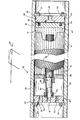
- the permeator is indicated generally as 30.
- Salt water is fed into port 31 in end plate 32.which is held in place in shell 33 by means of bolts 34/segmented ring 35.
- End plate sleeve 36 is threadably mounted in end plate 32 and receives feed tube 37.
- Permeator sleeve 38 serves to mount deflector block 39 and distributor 40 on feed tube 37.
- Deflector block 39 serves to hold permeator tubes or capillaries 41 in place.
- Feed water in feed tube 37 is fed from feed tube 37 through distributor 40 into the zone in the permeator containing capillaries 41.
- Feed tube 37 is foraminous between deflector block 39 and tube sheet 45 into which the open ends of capillaries 41 are mounted.
- a permeator 70 is depicted in which support block 71 is held in permanent contact with tube sheet 72 by means of bolt 73 and washer 74, instead of the springs used in the permeator depicted in Fig. 2.
- the remainder of permeator 70 is similar to permeator 30 depicted in Fig. 2.
- an elevated drawback tank on the product side of the permeator is used to supply this water which results in the product water pressure being greater than the feed brine pressure during shutdown.
- new feed tube 37 is normally cut to length fairly accurately, but it has now been discovered that after being in use there is deformation of tube sheet 45 and support block 47 so that during a shut down there is movement of the tube sheet away from the support block. It has now been found that when the tube sheet and support block reengage upon start up, there is relative rotational movement which causes damage to the ends of the capillaries and results in a decrease in both throughput of desalinated water and salt rejection. The decrease in salt rejection is believed to be due to an increase in pressure within the end damaged capillaries which results in decreased flow of desalinated water while about the same amount of salt is transmitted through the capillaries since this is less of a pressure dependent function.
- the spring loaded technique of maintaining the tube sheet and support block in constant intimate contact as shown in Fig. 2 is the preferred technique.
- the use of hydraulic pressure from the feed end of the permeator can be used such as with an apparatus similar to that shown in Fig. 1 but modified so that there is a brine water line elevated above the supply of draw back water during shut down.
- a third less preferred technique is to mechanically attach the tube sheet and support block together such as by taping or bolting.
- test stand used for the experiments is shown in Figure 1.
- the product water drawback tank was elevated 7.3 meters above the permeator to create a product pressure at shutdown of 10-11 psig.
- a Du Pont model 6840T B-10 permeator was modified as described below in order to incorporate compression coil springs. These springs are positioned so that they always force the support block into intimate contact with the epoxy tube sheet face.
- On-off cycle testing was performed using this permeator with the unmodified test stand shown in Fig. 1 and test procedure previously described.
- the bundle movement varied between 3.1 and 9.5 mm, but as determined by special measuring devices separation of the support block ana tube sheet face did not occur.
- the product flow did not change.
- the salt passage increased by 40% from an initial salt passage of 0.5%.
- the tube sheet face had a sheen appearance which indicates that separation and relative rotation of the support block and tube sheet face did not occur.
- a new B-10 permeator was selected and the support block was bolted to the face of the tube sheet using a single bolt through the support block and part way into the tube sheet where a hole was bored and threads tapped to receive the bolt (see Fig. 3).
- On-off cycle testing was then performed. After 260 cycles, within experimental error, no change in the product flow or salt passage was observed. During the cycling, bundle movement varied between 3.2 and 4.0 mm. After 260 cycles, the support block was unbolted and the cycling was resumed using the same support block. After only an additional 102 cycles, the product flow had decreased by 11.1% while the salt pasage increased by 16.7% (relative). The support block was then rotated approximately 10° manually after each cycle. After only 10 cycles (10 rotations), the product flow decreased an additional 10.9% but the salt passage did not change.
- the reject line was extended to a higher level (about 1.5 meters) than the water level in the drawback tank (see dashed line 25 in Figure 1).
- the fiber bundle will not move because the feed-brine pressure (12-13 psi or 83-90 kPa) is greater than the product pressure (10 psig or 69 kPa).
- the ⁇ P of 2-3 psi (14-21 kPa) is caused by the greater static head in the reject line.
- the process modification the product drawback still occurs but the fiber bundle and support block do not move.
- the permeator was then cycled for 150 times using the procedure which allowed bundle movement.
- the bundle movement was 15.9 mm and the separation between the support block and tube sheet face during shutdown was 6.4 mm.
- the product decreased by 9.9% and the salt passage increased by 9.1% (relative).
- the support block was then rotated 10° manually after each cycle for a total of 10 cycles. This caused a decrease of 5.8% in the product flow and an increase of 4.2% (relative) in the salt passage.
- the product flow decreased by 15.1% while the salt passage increased by 13.6% (relative).
- the permeator was then cycled 150 times using the modified process with no bundle movement. This decreased the product flow by only 2.9% and increased the salt passage by only 4.2% (relative). If the results with no bundle movement are summarized, after 410 on-off cycles (one shutdown and start-up every 4.5 days over 5 years of operation) the product flow decreased by 6.1% (versus a projected product flow loss of 4.0% caused by normal membrane compaction) and the salt passage increased by 14.7% (relative).
Landscapes
- Engineering & Computer Science (AREA)
- Manufacturing & Machinery (AREA)
- Chemical & Material Sciences (AREA)
- Chemical Kinetics & Catalysis (AREA)
- Separation Using Semi-Permeable Membranes (AREA)
Priority Applications (1)
| Application Number | Priority Date | Filing Date | Title |
|---|---|---|---|
| AT86303452T ATE48539T1 (de) | 1985-05-08 | 1986-05-07 | Umkehrosmose-permationsvorrichtung. |
Applications Claiming Priority (2)
| Application Number | Priority Date | Filing Date | Title |
|---|---|---|---|
| US06/731,729 US4675109A (en) | 1985-05-08 | 1985-05-08 | Reverse osmosis permeator |
| US731729 | 1985-05-08 |
Publications (3)
| Publication Number | Publication Date |
|---|---|
| EP0201320A2 true EP0201320A2 (de) | 1986-11-12 |
| EP0201320A3 EP0201320A3 (en) | 1987-01-14 |
| EP0201320B1 EP0201320B1 (de) | 1989-12-13 |
Family
ID=24940727
Family Applications (1)
| Application Number | Title | Priority Date | Filing Date |
|---|---|---|---|
| EP86303452A Expired EP0201320B1 (de) | 1985-05-08 | 1986-05-07 | Umkehrosmose-Permationsvorrichtung |
Country Status (11)
| Country | Link |
|---|---|
| US (1) | US4675109A (de) |
| EP (1) | EP0201320B1 (de) |
| JP (1) | JPH0687956B2 (de) |
| AR (1) | AR240870A1 (de) |
| AT (1) | ATE48539T1 (de) |
| AU (1) | AU582237B2 (de) |
| BR (1) | BR8602009A (de) |
| CA (1) | CA1274185A (de) |
| DE (1) | DE3667403D1 (de) |
| ES (1) | ES8707118A1 (de) |
| MX (1) | MX165361B (de) |
Cited By (1)
| Publication number | Priority date | Publication date | Assignee | Title |
|---|---|---|---|---|
| US5071552A (en) * | 1990-12-20 | 1991-12-10 | Union Carbide Industrial Gases Technology Corporation | Multiple bundle fluid separation apparatus |
Families Citing this family (10)
| Publication number | Priority date | Publication date | Assignee | Title |
|---|---|---|---|---|
| JPH0361922U (de) * | 1989-10-24 | 1991-06-18 | ||
| JP2532777Y2 (ja) * | 1990-05-28 | 1997-04-16 | 旭化成工業株式会社 | 濾過モジュールの取付装置 |
| US5137631A (en) * | 1991-10-22 | 1992-08-11 | E. I. Du Pont De Nemours And Company | Multiple bundle permeator |
| US5470469A (en) * | 1994-09-16 | 1995-11-28 | E. I. Du Pont De Nemours And Company | Hollow fiber cartridge |
| US6149817A (en) * | 1999-03-08 | 2000-11-21 | Celgard Inc. | Shell-less hollow fiber membrane fluid contactor |
| US6558544B1 (en) | 2000-12-04 | 2003-05-06 | Progressive Composite Technologies, Inc. | Pressure vessels for holding cylindrical semipermeable membrane cartridges |
| NZ561082A (en) * | 2005-03-29 | 2009-12-24 | Grahamtek Technologies Singapo | Manufacture of casings for use in the desalination of water and the filtration of liquids |
| WO2008081877A1 (ja) * | 2006-12-29 | 2008-07-10 | Ube Industries, Ltd. | シェルフィード型ガス分離膜モジュール |
| JP5135854B2 (ja) * | 2007-03-30 | 2013-02-06 | 宇部興産株式会社 | シェルフィード型ガス分離膜モジュール |
| JP6051687B2 (ja) * | 2012-08-29 | 2016-12-27 | 宇部興産株式会社 | ガス分離膜モジュール |
Family Cites Families (12)
| Publication number | Priority date | Publication date | Assignee | Title |
|---|---|---|---|---|
| DE123476C (de) * | 1960-09-19 | |||
| US3526001A (en) * | 1968-11-26 | 1970-08-25 | Du Pont | Permeation separation device for separating fluids and process relating thereto |
| US3583907A (en) * | 1969-07-16 | 1971-06-08 | Monsanto Co | Elongated capillary dialyzer |
| US3702658A (en) * | 1971-02-24 | 1972-11-14 | Du Pont | Permeation separation apparatus |
| US3760949A (en) * | 1971-08-13 | 1973-09-25 | Us Interior | Sealing means for hollow fiber bundles |
| DD95834A1 (de) * | 1971-12-17 | 1973-02-20 | ||
| AU516562B2 (en) * | 1977-04-08 | 1981-06-11 | Dow Chemical Company, The | Hollow fibre separatory device |
| US4315819A (en) * | 1978-06-12 | 1982-02-16 | Monsanto Company | Hollow fiber permeator apparatus |
| DE2950426C2 (de) * | 1978-12-22 | 1983-06-01 | Monsanto Co., 63166 St. Louis, Mo. | Vorrichtung zum Trennen von Strömungsmitteln |
| US4265763A (en) * | 1979-10-18 | 1981-05-05 | Monsanto Company | Permeator apparatus |
| FR2503129A1 (fr) * | 1981-04-06 | 1982-10-08 | Lopez Fernand | Dispositif de production d'eau douce a partir d'eau de mer par osmose inverse |
| US4517720A (en) * | 1981-12-21 | 1985-05-21 | Monsanto Company | Method of mounting a fluid separation module in a tubular shell |
-
1985
- 1985-05-08 US US06/731,729 patent/US4675109A/en not_active Expired - Fee Related
-
1986
- 1986-05-01 CA CA000508121A patent/CA1274185A/en not_active Expired - Lifetime
- 1986-05-05 BR BR8602009A patent/BR8602009A/pt unknown
- 1986-05-06 AU AU57189/86A patent/AU582237B2/en not_active Ceased
- 1986-05-07 DE DE8686303452T patent/DE3667403D1/de not_active Expired - Lifetime
- 1986-05-07 AT AT86303452T patent/ATE48539T1/de not_active IP Right Cessation
- 1986-05-07 EP EP86303452A patent/EP0201320B1/de not_active Expired
- 1986-05-07 MX MX002409A patent/MX165361B/es unknown
- 1986-05-07 AR AR303878A patent/AR240870A1/es active
- 1986-05-08 JP JP61103955A patent/JPH0687956B2/ja not_active Expired - Lifetime
- 1986-05-08 ES ES554762A patent/ES8707118A1/es not_active Expired
Cited By (1)
| Publication number | Priority date | Publication date | Assignee | Title |
|---|---|---|---|---|
| US5071552A (en) * | 1990-12-20 | 1991-12-10 | Union Carbide Industrial Gases Technology Corporation | Multiple bundle fluid separation apparatus |
Also Published As
| Publication number | Publication date |
|---|---|
| CA1274185A (en) | 1990-09-18 |
| EP0201320B1 (de) | 1989-12-13 |
| AR240870A1 (es) | 1991-03-27 |
| AR240870A2 (es) | 1991-03-27 |
| ATE48539T1 (de) | 1989-12-15 |
| ES8707118A1 (es) | 1987-07-16 |
| MX165361B (es) | 1992-11-06 |
| JPH0687956B2 (ja) | 1994-11-09 |
| JPS61259708A (ja) | 1986-11-18 |
| AU582237B2 (en) | 1989-03-16 |
| AU5718986A (en) | 1986-11-13 |
| ES554762A0 (es) | 1987-07-16 |
| DE3667403D1 (de) | 1990-01-18 |
| BR8602009A (pt) | 1987-01-06 |
| EP0201320A3 (en) | 1987-01-14 |
| US4675109A (en) | 1987-06-23 |
Similar Documents
| Publication | Publication Date | Title |
|---|---|---|
| US4675109A (en) | Reverse osmosis permeator | |
| US3839201A (en) | Reverse osmosis separator unit | |
| US4876012A (en) | Hollow fibre filter cartridge and header | |
| US4476015A (en) | Multiple element fluid separation device | |
| US5470469A (en) | Hollow fiber cartridge | |
| EP1598105B1 (de) | Hohlfasermembranmodul und modulanordnungsgruppe dafür | |
| US6324898B1 (en) | Method and apparatus for testing the integrity of filtering membranes | |
| US4293419A (en) | Hollow fiber membrane separation apparatus | |
| US5137631A (en) | Multiple bundle permeator | |
| US7186331B2 (en) | Monitoring unit for monitoring the condition of a semi-permeable membrane | |
| US20050029192A1 (en) | Branched flow filtraction and system | |
| US8596110B2 (en) | Device and method for testing reverse osmosis membranes | |
| CN103826729A (zh) | 改进的接触器、筒、组件、系统和相关方法 | |
| US5098562A (en) | Apparatus for treating deaerated water | |
| GB1429543A (en) | Supporting member for reverse osmosis membranes a process for manufacturing the member and a reverse osmotic filtration apparat | |
| US3608730A (en) | Desalination apparatus | |
| JP5037758B2 (ja) | 膜モジュールの完全性検査方法 | |
| JP2006231289A (ja) | 中空糸膜モジュ−ルのリーク検出方法およびリ−ク検出装置 | |
| JP2022165328A (ja) | 膜ろ過システム | |
| JPH09222375A (ja) | 海水リークの検出方法及びその装置 | |
| SU1667912A1 (ru) | Устройство дл ультрафильтрации | |
| CN221107744U (zh) | 反渗透膜壳 | |
| CN213060302U (zh) | 一种水处理用反渗透膜结构 | |
| Al-Mutaz et al. | Prediction performance of RO desalination plants | |
| JPH0651102B2 (ja) | 平膜分離装置における異常箇所の検知方法 |
Legal Events
| Date | Code | Title | Description |
|---|---|---|---|
| PUAI | Public reference made under article 153(3) epc to a published international application that has entered the european phase |
Free format text: ORIGINAL CODE: 0009012 |
|
| AK | Designated contracting states |
Kind code of ref document: A2 Designated state(s): AT BE CH DE FR GB IT LI NL |
|
| PUAL | Search report despatched |
Free format text: ORIGINAL CODE: 0009013 |
|
| AK | Designated contracting states |
Kind code of ref document: A3 Designated state(s): AT BE CH DE FR GB IT LI NL |
|
| 17P | Request for examination filed |
Effective date: 19870618 |
|
| 17Q | First examination report despatched |
Effective date: 19880613 |
|
| GRAA | (expected) grant |
Free format text: ORIGINAL CODE: 0009210 |
|
| AK | Designated contracting states |
Kind code of ref document: B1 Designated state(s): AT BE CH DE FR GB IT LI NL |
|
| REF | Corresponds to: |
Ref document number: 48539 Country of ref document: AT Date of ref document: 19891215 Kind code of ref document: T |
|
| ITF | It: translation for a ep patent filed | ||
| REF | Corresponds to: |
Ref document number: 3667403 Country of ref document: DE Date of ref document: 19900118 |
|
| ET | Fr: translation filed | ||
| PLBE | No opposition filed within time limit |
Free format text: ORIGINAL CODE: 0009261 |
|
| STAA | Information on the status of an ep patent application or granted ep patent |
Free format text: STATUS: NO OPPOSITION FILED WITHIN TIME LIMIT |
|
| 26N | No opposition filed | ||
| ITTA | It: last paid annual fee | ||
| PGFP | Annual fee paid to national office [announced via postgrant information from national office to epo] |
Ref country code: CH Payment date: 19940308 Year of fee payment: 9 |
|
| PGFP | Annual fee paid to national office [announced via postgrant information from national office to epo] |
Ref country code: AT Payment date: 19940412 Year of fee payment: 9 |
|
| PG25 | Lapsed in a contracting state [announced via postgrant information from national office to epo] |
Ref country code: AT Effective date: 19950507 |
|
| PG25 | Lapsed in a contracting state [announced via postgrant information from national office to epo] |
Ref country code: LI Effective date: 19950531 Ref country code: CH Effective date: 19950531 |
|
| REG | Reference to a national code |
Ref country code: CH Ref legal event code: PL |
|
| PGFP | Annual fee paid to national office [announced via postgrant information from national office to epo] |
Ref country code: FR Payment date: 19960315 Year of fee payment: 11 |
|
| PGFP | Annual fee paid to national office [announced via postgrant information from national office to epo] |
Ref country code: NL Payment date: 19960322 Year of fee payment: 11 Ref country code: DE Payment date: 19960322 Year of fee payment: 11 |
|
| PGFP | Annual fee paid to national office [announced via postgrant information from national office to epo] |
Ref country code: GB Payment date: 19960404 Year of fee payment: 11 |
|
| PGFP | Annual fee paid to national office [announced via postgrant information from national office to epo] |
Ref country code: BE Payment date: 19960409 Year of fee payment: 11 |
|
| PG25 | Lapsed in a contracting state [announced via postgrant information from national office to epo] |
Ref country code: GB Effective date: 19970507 |
|
| PG25 | Lapsed in a contracting state [announced via postgrant information from national office to epo] |
Ref country code: BE Effective date: 19970531 |
|
| BERE | Be: lapsed |
Owner name: E.I. DU PONT DE NEMOURS AND CY (A DELAWARE CORP.) Effective date: 19970531 |
|
| PG25 | Lapsed in a contracting state [announced via postgrant information from national office to epo] |
Ref country code: NL Effective date: 19971201 |
|
| GBPC | Gb: european patent ceased through non-payment of renewal fee |
Effective date: 19970507 |
|
| PG25 | Lapsed in a contracting state [announced via postgrant information from national office to epo] |
Ref country code: FR Free format text: LAPSE BECAUSE OF NON-PAYMENT OF DUE FEES Effective date: 19980130 |
|
| NLV4 | Nl: lapsed or anulled due to non-payment of the annual fee |
Effective date: 19971201 |
|
| PG25 | Lapsed in a contracting state [announced via postgrant information from national office to epo] |
Ref country code: DE Free format text: LAPSE BECAUSE OF NON-PAYMENT OF DUE FEES Effective date: 19980203 |
|
| REG | Reference to a national code |
Ref country code: FR Ref legal event code: ST |
|
| PG25 | Lapsed in a contracting state [announced via postgrant information from national office to epo] |
Ref country code: IT Free format text: LAPSE BECAUSE OF NON-PAYMENT OF DUE FEES;WARNING: LAPSES OF ITALIAN PATENTS WITH EFFECTIVE DATE BEFORE 2007 MAY HAVE OCCURRED AT ANY TIME BEFORE 2007. THE CORRECT EFFECTIVE DATE MAY BE DIFFERENT FROM THE ONE RECORDED. Effective date: 20050507 |