EP0201395B2 - Einrichtung zum Zusammenbau, insbesondere für Karosseriebearbeitungsstrassen - Google Patents
Einrichtung zum Zusammenbau, insbesondere für Karosseriebearbeitungsstrassen Download PDFInfo
- Publication number
- EP0201395B2 EP0201395B2 EP86400866A EP86400866A EP0201395B2 EP 0201395 B2 EP0201395 B2 EP 0201395B2 EP 86400866 A EP86400866 A EP 86400866A EP 86400866 A EP86400866 A EP 86400866A EP 0201395 B2 EP0201395 B2 EP 0201395B2
- Authority
- EP
- European Patent Office
- Prior art keywords
- tools
- tool
- geometry
- magazine
- station
- Prior art date
- Legal status (The legal status is an assumption and is not a legal conclusion. Google has not performed a legal analysis and makes no representation as to the accuracy of the status listed.)
- Expired - Lifetime
Links
- 238000003860 storage Methods 0.000 claims description 7
- 238000009826 distribution Methods 0.000 claims description 5
- 230000000712 assembly Effects 0.000 claims description 3
- 238000000429 assembly Methods 0.000 claims description 3
- 238000011144 upstream manufacturing Methods 0.000 claims description 3
- 230000010485 coping Effects 0.000 claims 1
- 238000004519 manufacturing process Methods 0.000 description 4
- 238000003466 welding Methods 0.000 description 3
- 230000001133 acceleration Effects 0.000 description 1
- 238000007599 discharging Methods 0.000 description 1
- 238000009434 installation Methods 0.000 description 1
- 238000000034 method Methods 0.000 description 1
- 230000000750 progressive effect Effects 0.000 description 1
- 230000000717 retained effect Effects 0.000 description 1
- 238000005096 rolling process Methods 0.000 description 1
Images




Classifications
-
- B—PERFORMING OPERATIONS; TRANSPORTING
- B62—LAND VEHICLES FOR TRAVELLING OTHERWISE THAN ON RAILS
- B62D—MOTOR VEHICLES; TRAILERS
- B62D65/00—Designing, manufacturing, e.g. assembling, facilitating disassembly, or structurally modifying motor vehicles or trailers, not otherwise provided for
- B62D65/02—Joining sub-units or components to, or positioning sub-units or components with respect to, body shell or other sub-units or components
-
- B—PERFORMING OPERATIONS; TRANSPORTING
- B23—MACHINE TOOLS; METAL-WORKING NOT OTHERWISE PROVIDED FOR
- B23K—SOLDERING OR UNSOLDERING; WELDING; CLADDING OR PLATING BY SOLDERING OR WELDING; CUTTING BY APPLYING HEAT LOCALLY, e.g. FLAME CUTTING; WORKING BY LASER BEAM
- B23K37/00—Auxiliary devices or processes, not specially adapted for a procedure covered by only one of the other main groups of this subclass
- B23K37/04—Auxiliary devices or processes, not specially adapted for a procedure covered by only one of the other main groups of this subclass for holding or positioning work
- B23K37/047—Auxiliary devices or processes, not specially adapted for a procedure covered by only one of the other main groups of this subclass for holding or positioning work moving work to adjust its position between soldering, welding or cutting steps
-
- B—PERFORMING OPERATIONS; TRANSPORTING
- B23—MACHINE TOOLS; METAL-WORKING NOT OTHERWISE PROVIDED FOR
- B23P—METAL-WORKING NOT OTHERWISE PROVIDED FOR; COMBINED OPERATIONS; UNIVERSAL MACHINE TOOLS
- B23P2700/00—Indexing scheme relating to the articles being treated, e.g. manufactured, repaired, assembled, connected or other operations covered in the subgroups
- B23P2700/50—Other automobile vehicle parts, i.e. manufactured in assembly lines
-
- Y—GENERAL TAGGING OF NEW TECHNOLOGICAL DEVELOPMENTS; GENERAL TAGGING OF CROSS-SECTIONAL TECHNOLOGIES SPANNING OVER SEVERAL SECTIONS OF THE IPC; TECHNICAL SUBJECTS COVERED BY FORMER USPC CROSS-REFERENCE ART COLLECTIONS [XRACs] AND DIGESTS
- Y10—TECHNICAL SUBJECTS COVERED BY FORMER USPC
- Y10T—TECHNICAL SUBJECTS COVERED BY FORMER US CLASSIFICATION
- Y10T29/00—Metal working
- Y10T29/49—Method of mechanical manufacture
- Y10T29/49826—Assembling or joining
- Y10T29/49828—Progressively advancing of work assembly station or assembled portion of work
-
- Y—GENERAL TAGGING OF NEW TECHNOLOGICAL DEVELOPMENTS; GENERAL TAGGING OF CROSS-SECTIONAL TECHNOLOGIES SPANNING OVER SEVERAL SECTIONS OF THE IPC; TECHNICAL SUBJECTS COVERED BY FORMER USPC CROSS-REFERENCE ART COLLECTIONS [XRACs] AND DIGESTS
- Y10—TECHNICAL SUBJECTS COVERED BY FORMER USPC
- Y10T—TECHNICAL SUBJECTS COVERED BY FORMER US CLASSIFICATION
- Y10T29/00—Metal working
- Y10T29/49—Method of mechanical manufacture
- Y10T29/49826—Assembling or joining
- Y10T29/49828—Progressively advancing of work assembly station or assembled portion of work
- Y10T29/49829—Advancing work to successive stations [i.e., assembly line]
-
- Y—GENERAL TAGGING OF NEW TECHNOLOGICAL DEVELOPMENTS; GENERAL TAGGING OF CROSS-SECTIONAL TECHNOLOGIES SPANNING OVER SEVERAL SECTIONS OF THE IPC; TECHNICAL SUBJECTS COVERED BY FORMER USPC CROSS-REFERENCE ART COLLECTIONS [XRACs] AND DIGESTS
- Y10—TECHNICAL SUBJECTS COVERED BY FORMER USPC
- Y10T—TECHNICAL SUBJECTS COVERED BY FORMER US CLASSIFICATION
- Y10T29/00—Metal working
- Y10T29/51—Plural diverse manufacturing apparatus including means for metal shaping or assembling
- Y10T29/5124—Plural diverse manufacturing apparatus including means for metal shaping or assembling with means to feed work intermittently from one tool station to another
-
- Y—GENERAL TAGGING OF NEW TECHNOLOGICAL DEVELOPMENTS; GENERAL TAGGING OF CROSS-SECTIONAL TECHNOLOGIES SPANNING OVER SEVERAL SECTIONS OF THE IPC; TECHNICAL SUBJECTS COVERED BY FORMER USPC CROSS-REFERENCE ART COLLECTIONS [XRACs] AND DIGESTS
- Y10—TECHNICAL SUBJECTS COVERED BY FORMER USPC
- Y10T—TECHNICAL SUBJECTS COVERED BY FORMER US CLASSIFICATION
- Y10T29/00—Metal working
- Y10T29/51—Plural diverse manufacturing apparatus including means for metal shaping or assembling
- Y10T29/5191—Assembly
-
- Y—GENERAL TAGGING OF NEW TECHNOLOGICAL DEVELOPMENTS; GENERAL TAGGING OF CROSS-SECTIONAL TECHNOLOGIES SPANNING OVER SEVERAL SECTIONS OF THE IPC; TECHNICAL SUBJECTS COVERED BY FORMER USPC CROSS-REFERENCE ART COLLECTIONS [XRACs] AND DIGESTS
- Y10—TECHNICAL SUBJECTS COVERED BY FORMER USPC
- Y10T—TECHNICAL SUBJECTS COVERED BY FORMER US CLASSIFICATION
- Y10T29/00—Metal working
- Y10T29/53—Means to assemble or disassemble
- Y10T29/534—Multiple station assembly or disassembly apparatus
-
- Y—GENERAL TAGGING OF NEW TECHNOLOGICAL DEVELOPMENTS; GENERAL TAGGING OF CROSS-SECTIONAL TECHNOLOGIES SPANNING OVER SEVERAL SECTIONS OF THE IPC; TECHNICAL SUBJECTS COVERED BY FORMER USPC CROSS-REFERENCE ART COLLECTIONS [XRACs] AND DIGESTS
- Y10—TECHNICAL SUBJECTS COVERED BY FORMER USPC
- Y10T—TECHNICAL SUBJECTS COVERED BY FORMER US CLASSIFICATION
- Y10T29/00—Metal working
- Y10T29/53—Means to assemble or disassemble
- Y10T29/53539—Means to assemble or disassemble including work conveyor
- Y10T29/53543—Means to assemble or disassemble including work conveyor including transporting track
Definitions
- the present invention relates to a body assembly device known per se, of the type adapted to a plurality of vehicle models and their variants and provided with geometry and finishing stations.
- the document GB-A-2 114 067 describes a conventional assembly station by welding for bases and openings of vehicle bodies.
- the tools are carried on side frames which can move parallel to the transfer axis while being indexable at the work station.
- This arrangement is illustrated by document DE-A-2 810 822.
- this document describes a body assembly device of the type adapted to a plurality of vehicle models and their variants comprising means for supplying a roughly assembled body, means for evacuating the assembled body, a geometry station and finishing, means for storing geometry tools, means for their distribution and presentation at the geometry setting station and robots or assembly operators.
- the geometry tools additionally comprise frames, in a known manner, a lower tool supported by movable carriages running on rails below fixed tables with rollers which allow the movement of handling sleds in cooperation with roller boxes mounted on elevators, operating the loading of said lower tool.
- a pair of frames is specific to a specific body.
- the subject of the invention is a device for assembling bodies of the type suitable for a plurality of vehicle models and their variants comprising means for supplying a body which has been summarily assembled, means for discharging the assembled bodywork, a geometry and finishing station comprising means for storing geometry tools, their distribution and presentation means at the geometry station and robots or assembly operators, in which the geometry tools comprise in known manner a lower tool supported by mobile carriages circulating on rails below fixed tables with rollers which allow the movement of handling sleds in cooperation with roller housings mounted on elevators, operating the loading of said lower tooling, upper front tooling and rear upper tooling, the tools are uppers being, in the active position facing the body, coupled to a reference roll bar by means of a horizontal pivot axis of this tool, the lower tool cooperating in the active position with each upper tool articulated on the reference roll bar by a refocusing foot which is carried by the lower tool, while the means of distribution and presentation of the upper tools are provided between the reference frame and the storage means.
- This feature makes it possible to make an installation for implementing this process perfectly convertible and flexible.
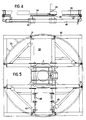
- the storage means are formed by a gantry and two symmetrical assemblies each comprising a rotary magazine of vertical axis with upper tools driven by a slewing ring, a pinion and a servo geared motor, the means of handling of the upper tools from the storage station to their active position comprising a vertically movable scissor table.
- the rotary magazine provides a large number of superior tools.
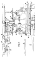
- this body assembly device is made up of two separate parts: a machine module 4 and a structure module 6.
- This machine module comprises a portal frame known as a reference hoop 14 for receiving upper tools 8, 10 and lower 12, fixed tables 16 with rollers on which handling sleds 18 move, side boxes 20 with rollers mounted on elevators 22 and capable of receiving these sleds, and mobile carriages 24 which can be coupled to a motorized shuttle-cart 26, each surmounted by a tool lower 12 and running on rails 28 below these fixed tables 16.
- a portal frame known as a reference hoop 14 for receiving upper tools 8, 10 and lower 12
- fixed tables 16 with rollers on which handling sleds 18 move side boxes 20 with rollers mounted on elevators 22 and capable of receiving these sleds
- mobile carriages 24 which can be coupled to a motorized shuttle-cart 26, each surmounted by a tool lower 12 and running on rails 28 below these fixed tables 16.
- the mobile carriages 24 move in the transfer direction on the rails 28 below the raceway of the handling sleds 18 which carry the bodies 2.
- Each carriage has a removable platform on which is fixed a body-specific lower tools.
- a guide rail 27 on which two sets of two rollers with a vertical axis rest, is disposed between the rails 28.
- a rack is fixed on this guide rail so as to cooperate with a pinion integral with this carriage.
- a servo motor is on board the shuttle carriage 26 which is interposed between two mobile carriages 24.
- a clamping system is provided to obtain a precise stop position in the transfer direction, and a locking of all of these carriages .
- a mobile carriage can be removed perpendicular to the transfer axis at respective exchange stations 60 and 62.
- bodywork there is provided a single lower tool 12 and two upper tools 8, 10 intended respectively at the front and at the rear thereof.
- a change in the configuration of the workstation is therefore envisaged during the transfer time of a bodywork to pass another type of bodywork.
- a basic version provides four types of lower tools and four types of upper tools, front or rear.
- a possible extension consists in associating with the rotary magazines 32, 32 ′, upper tool changers and with the machine module 4, lower tool changers.
- the upper front 8 and rear 10 tools are driven by two identical control systems.
- the tools 8, 10 are put in place by the flaps 40, 40 '.
- the lateral parts of the assembly station can be released to facilitate the passage of operators 68 or robots 70.
- the rotary magazine 32, 32 ' is designed to receive four upper tools 8 i , 10 i which rest on eight stretchers 46, 46 'linked to a drum. It has rollers 31, 31 'on its periphery and can rotate on a crown 33, 33' secured to the gantry 30.
- the rotation of the slewing ring 34, 34 'linked to the magazine 32, 32' is carried out by a servo-geared motor 38, 38 'attacking a pinion 36, 36'.
- This servo motor allows programming of acceleration and deceleration ramps, and obtaining a precise stop in position.
- An indexing system ensures this precise stop by bringing the rotary magazine back to the planned position if necessary, and also controls its locking in this position.
- a second cylinder can be associated with the cylinder 58, 58 ′.
- the upper tool 8, 10 is referenced and clamped on the portal frame 14 called the reference hoop and the lower tool 12, respectively via the horizontal pivot axis 44, 44 ' of this upper tool, and of a centering foot 64, 66 secured to this lower tool.
- This tool is then clamped on the flap and raised to the level of stretchers 46, 46 '. This flap is then locked in the high position.
- the rise automatically ensures the opening of the articulated cleats 48, 48 'via of a cam. An overtravel is made to close these cleats.
- the body assembly device described above operates as follows, following a complete work cycle, with reference to FIGS. 1, 2 and 3.
- a roughly assembled bodywork 2 and placed on the handling sledge is directed towards the work station by rolling on the fixed table 16 then on the roller housings 20.
- the assembly formed by the body, the sledge and the roller housings is then lowered under the action of the risers 22 until the body rests on the references of the lower tool 12.
- the operators 68 or the robots 70 then intervene to execute the assembly of the bodywork, for example by welding.
- the elevators 22 sequentially raise the body-sledge-roller casing assembly at the level of the fixed table 16.
- the assembled bodywork is then evacuated to the downstream station, while a new bodywork arrives at the workstation.
- the upper tools are changed as in the second case.
- the lower tools on board a mobile cart 24 coupled to the motorized shuttle cart 26 is changed, either by indexing at the work station, of the other mobile carriage coupled to this shuttle carriage, or by replacement of one of them by a mobile carriage carrying the appropriate tools, waiting at the station upstream exchange 60 or downstream 62, outside the transfer line.
Landscapes
- Engineering & Computer Science (AREA)
- Mechanical Engineering (AREA)
- Physics & Mathematics (AREA)
- Optics & Photonics (AREA)
- Manufacturing & Machinery (AREA)
- Chemical & Material Sciences (AREA)
- Combustion & Propulsion (AREA)
- Transportation (AREA)
- Automatic Assembly (AREA)
- Multi-Process Working Machines And Systems (AREA)
- Automobile Manufacture Line, Endless Track Vehicle, Trailer (AREA)
Claims (7)
- Vorrichtung zum Zusammenbau von Karosserien der für eine Mehrzahl von Fahrzeugmodellen geeigneten Art und ihrer Varianten, umfassend Mittel zum Zuführen einer summarisch zusammengebauten Karosserie (2), Mittel zum Abtransport der zusammengebauten Karosserie, eine Station zum Richten und Fertigstellen mit Mitteln zum Speichern von Richtwerkzeuganordnungen (8, 10, 12), Mitteln zu ihrer Verteilung und ihrer Bereitstellung an der Richtstation, sowie Roboter (70) oder Bedienungspersonen (68) zum Zusammenbau, bei welcher die Richtwerkzeuge eine untere Werkzeuganordnung (12), die von beweglichen Wagen (24) getragen ist, die an einen motorisierten Pendelwagen (26) koppelbar sind, der auf Schienen (28) unter feststehenden Rollentischen (16) läuft, welche im Zusammenwirken mit auf Hubvorrichtungen (22) montierten Rollenkästen (20) die Bewegung von Transportschlitten (18) ermöglichen, wobei die Hubvorrichtungen das Beladen der unteren Werkzeuganordnung (12) bewirken, eine vordere obere Werkzeuganordnung (8) und eine hintere obere Werkzeuganordnung (10) umfassen, wobei die obere Werkzeuganordnung (8, 10) in ihrer Arbeitsstellung gegenüber der Karosserie an einem Referenzportal (14) mittels einer horizontalen Schwenkachse (44, 44') dieser Werkzeuganordnung angehängt sind und wobei die untere Werkzeuganordnung (12) in der Arbeitsstellung mit jeder an dem Referenzportal angelenkten oberen Werkzeug (8, 10) über einen Zentrierfuß zusammenwirkt, der von der unteren Werkzeuganordnung getragen ist, wogegen die Mittel zur Verteilung und zur Bereitstellung (30, 42, 42') der oberen Werkzeuganordnung (8, 10) zwischen dem Referenzportal (14) und der Speichereinrichtung (32, 32') vorgesehen sind.
- Vorrichtung nach Anspruch 1, dadurch gekennzeichnet, daß die Speichereinrichtung von einem Portal (30) und zwei symmetrischen Anordnungen gebildet ist, von denen jede ein um eine vertikale Achse drehbares Drehmagazin (32, 32') für die obere Werkzeuganordnung (8, 10) umfaßt, das über einen Drehkranz (34, 34'), ein Ritzel (36, 36') und einen geregelten Getriebemotor (38, 38') angetrieben ist, wobei die Transportmittel zum Transport der oberen Werkzeuganordnungen (8, 10) von der Speicherstation zu ihrer Arbeitsstellung einen vertikal verstellbaren Scherengelenktisch (42, 42') umfassen.
- Vorrichtung nach Anspruch 2, dadurch gekennzeichnet, daß das vordere und das hintere Drehmagazin (32, 32') jeweils Träger (46, 46') zum Tragen mindestens zweier oberer Werkzeuganordnungen (8, 10) haben, an denen sie mit Hilfe von Gelenkklauen (48, 48') verriegelt und gehalten sind.
- Vorrichtung nach Anspruch 2, dadurch gekennzeichnet, daß zur Ermöglichung einer Drehung des Magazins (32, 32') die Positionierung und die Verriegelung einer oberen Werkzeuganordnung (8, 10) an dem Scherengelenktisch (42, 42') mit Hilfe von am Tisch befestigten Zapfen (50, 50') und t-förmigen Nuten (52, 52') erfolgt, die in der Werkzeuganordnung (8, 10) ausgebildet sind und in die die genannten Zapfen (50, 50') eingreifen können, die von Stellzylindern (54, 54') bewegt werden, wobei die Achse der Translationsbewegung der Zapfen/Nut-Paare tangential zur Relativbewegung der Werkzeuganordnung, die mit Hilfe des Drehmagazins verstellt wird.
- Vorrichtung nach einem der Ansprüche 2 bis 4, dadurch gekennzeichnet, daß die Drehmagazine (32, 32') an ihrem Umfang mit Stützrollen-Fahrgestellen (31, 31') versehen sind, die auf einem mit dem Portal (30) verbundenen Kranz (33, 33') laufen.
- Vorrichtung nach einem der Ansprüche 2 bis 5, dadurch gekennzeichnet, daß ein Werkzeugwechsler mit jedem Drehmagazin (32, 32') verbunden sein kann, um die Speicherkapazität für obere Werkzeuganordnungen zu erhöhen.
- Vorrichtung nach Anspruch 1, dadurch gekennzeichnet, daß Wechselstationen (60, 62), welche verschiedene untere Werkzeuganordnungen tragende mobile Wagen aufnehmen, stromaufwärts und stromabwärts der Arbeitsstation senkrecht zur Transportrichtung der Karosserien vorgesehen sind.
Applications Claiming Priority (2)
| Application Number | Priority Date | Filing Date | Title |
|---|---|---|---|
| FR8506540A FR2580973B1 (fr) | 1985-04-30 | 1985-04-30 | Procede et dispositif d'assemblage destines notamment aux lignes capacitaires de carrosseries |
| FR8506540 | 1985-04-30 |
Publications (3)
| Publication Number | Publication Date |
|---|---|
| EP0201395A1 EP0201395A1 (de) | 1986-11-12 |
| EP0201395B1 EP0201395B1 (de) | 1990-01-03 |
| EP0201395B2 true EP0201395B2 (de) | 1995-06-14 |
Family
ID=9318811
Family Applications (1)
| Application Number | Title | Priority Date | Filing Date |
|---|---|---|---|
| EP86400866A Expired - Lifetime EP0201395B2 (de) | 1985-04-30 | 1986-04-22 | Einrichtung zum Zusammenbau, insbesondere für Karosseriebearbeitungsstrassen |
Country Status (7)
| Country | Link |
|---|---|
| US (1) | US4670961A (de) |
| EP (1) | EP0201395B2 (de) |
| CA (1) | CA1259781A (de) |
| DE (1) | DE3667931D1 (de) |
| ES (1) | ES8800858A1 (de) |
| FR (1) | FR2580973B1 (de) |
| PT (1) | PT82474B (de) |
Families Citing this family (43)
| Publication number | Priority date | Publication date | Assignee | Title |
|---|---|---|---|---|
| DE3506314A1 (de) * | 1985-02-22 | 1986-08-28 | Kuka Schweissanlagen + Roboter Gmbh, 8900 Augsburg | Verfahren und vorrichtung zum automatischen fuegen und bearbeiten |
| DE3545537A1 (de) * | 1985-12-21 | 1987-07-02 | Audi Ag | Vorrichtung zum automatischen bearbeiten unterschiedlich geformter werkstuecke |
| GB2206316B (en) * | 1987-03-28 | 1991-03-20 | Lamb Technicon Uk Operations C | Holding apparatus for a vehicle assembly line |
| FR2645059A2 (fr) * | 1988-02-17 | 1990-10-05 | Renault Automation | Procede et dispositif d'assemblage carrosserie a outillages lateraux interlocalisables |
| FR2627116B1 (fr) * | 1988-02-17 | 1994-03-25 | Renault Automation | Procede et dispositif pour l'interlocalisation des outillages d'une machine d'assemblage de carrosseries |
| JPH0622768B2 (ja) * | 1988-04-05 | 1994-03-30 | 本田技研工業株式会社 | 組付装置 |
| EP0390635B1 (de) * | 1989-03-28 | 1993-06-09 | Renault Automation | Vorrichtung zum Zusammenbauen einer Karosserie mittels positionierbaren Seitenwerkzeugen |
| US4939838A (en) * | 1989-04-03 | 1990-07-10 | Gatta Raymond P | Compliant positioning system for operating on assembly line products |
| US5083357A (en) * | 1989-04-06 | 1992-01-28 | Honda Giken Kogyo Kabushiki Kaisha | Method of and apparatus for assembling door handle |
| US5208966A (en) * | 1989-04-06 | 1993-05-11 | Honda Giken Kogyo Kabushiki Kaisha | Apparatus for assembling door handle |
| US5011068A (en) * | 1989-12-05 | 1991-04-30 | Progressive Tool & Industries Co. | Automotive body framing system |
| US4991707A (en) * | 1990-01-12 | 1991-02-12 | Progressive Tool & Industries Co. | Bodyside panel handling conveyor |
| US5141093A (en) * | 1991-04-17 | 1992-08-25 | Progressive Tool & Industries Co. | Automotive body panel handling apparatus |
| FR2707906B1 (fr) * | 1993-06-29 | 1995-09-15 | Renault Automation | Unité d'indexation précise d'une palette dans le référentiel d'un poste de travail. |
| US5409158A (en) * | 1993-07-08 | 1995-04-25 | Progressive Tool & Industries Company | Automobile framing system |
| IT1261269B (it) * | 1993-09-20 | 1996-05-09 | Comau Spa | Dispositivo per la saldatura a punti di strutture costituite da elementi di lamiera stampata, in particolare carrozzerie di autoveicoli |
| FR2712833B1 (fr) * | 1993-11-26 | 1996-01-05 | Renault Automation | Ligne organisée de postes d'assemblage pour sous-ensembles de carrosserie automobile. |
| US5427300A (en) * | 1994-03-22 | 1995-06-27 | Progressive Tool & Industries Co. | Apparatus for framing vehicle bodies |
| US5591358A (en) * | 1994-03-23 | 1997-01-07 | Progressive Tool & Industries Co. | Apparatus for clamping and laser welding |
| US5697752A (en) * | 1995-07-13 | 1997-12-16 | Progressive Tool & Industries Company | Overhead transfer clamp actuator and linkage |
| US5943768A (en) * | 1997-10-08 | 1999-08-31 | Valiant Machine & Tool Inc. | Automotive framing system |
| US5940961A (en) * | 1997-10-08 | 1999-08-24 | Valiant Machine & Tool Inc. | Automotive framing system |
| US6364600B1 (en) | 1999-03-19 | 2002-04-02 | Valiant Corporation | Pinion support |
| US6554119B2 (en) * | 2000-02-07 | 2003-04-29 | Progressive Tool & Industries Co. | Flexible automotive assembly line and method |
| US6557690B2 (en) | 2000-02-07 | 2003-05-06 | Progessive Tool & Industries Co. | Interchangeable nests for supporting components on a transport system |
| US6564440B2 (en) * | 2000-02-07 | 2003-05-20 | Progressive Tool & Industries Co. | Flexible automotive assembly workstation and method |
| US6364817B1 (en) | 2000-09-08 | 2002-04-02 | Unova Ip Corp. | Automotive framing apparatus |
| US20040055131A1 (en) * | 2002-09-24 | 2004-03-25 | Abid Ghuman | Method of assembling vehicles in a flexible manufacturing system |
| US7178227B2 (en) * | 2002-09-24 | 2007-02-20 | Ford Motor Company | Workpiece presenter for a flexible manufacturing system |
| US20040055129A1 (en) * | 2002-09-24 | 2004-03-25 | Abid Ghuman | Method of engineering a flexible process line |
| US20040056497A1 (en) * | 2002-09-24 | 2004-03-25 | Abid Ghuman | Flexible manufacturing system |
| US6899377B2 (en) * | 2002-09-24 | 2005-05-31 | Ford Motor Company | Vehicle body |
| US6918577B2 (en) | 2002-09-24 | 2005-07-19 | Ford Motor Company | Tooling plate for a flexible manufacturing system |
| US20040055147A1 (en) * | 2002-09-24 | 2004-03-25 | Abid Ghuman | Process line for a flexible manufacturing system |
| US20040056069A1 (en) * | 2002-09-24 | 2004-03-25 | Abid Ghuman | Method of engineering a process line for a flexible manufacturing system |
| DE60318604T2 (de) * | 2002-10-22 | 2009-01-15 | Daihatsu Motor Co., Ltd., Ikeda | Verfahren zur montage einer kraftfahrzeugkarosserie |
| US20050223532A1 (en) * | 2004-04-08 | 2005-10-13 | Ford Global Technologies, Llc | Method of designing a vehicle closure assembly line |
| DE102005027986B4 (de) * | 2005-06-16 | 2008-06-05 | Thyssenkrupp Drauz Nothelfer Gmbh | Verfahren und Anlage zum Zusammenbauen von Bauteilen einer Fahrzeugkarosserie |
| DE102008020083A1 (de) * | 2008-04-22 | 2009-10-29 | Dr. Ing. H.C. F. Porsche Aktiengesellschaft | Verfahren zur Fertigung von Kraftfahrzeugen |
| KR101220380B1 (ko) * | 2010-12-08 | 2013-01-09 | 기아자동차주식회사 | 차량용 패널 지그장치 |
| CN105904187B (zh) * | 2016-06-23 | 2018-02-09 | 鹤壁海昌专用设备有限公司 | 一种可快换多工位防水盲堵自动插入设备 |
| CN112452798B (zh) * | 2020-11-11 | 2023-06-16 | 中国电子科技集团公司第三十八研究所 | 一种基于视觉测量的连接器分拣装配系统 |
| CN118545449B (zh) * | 2024-05-30 | 2024-12-31 | 中国电器科学研究院股份有限公司 | 一种柔性往复输送机构 |
Family Cites Families (6)
| Publication number | Priority date | Publication date | Assignee | Title |
|---|---|---|---|---|
| US2779092A (en) * | 1951-12-26 | 1957-01-29 | Progressive Welder Sales Compa | Method and apparatus for making vehicle bodies |
| US4411354A (en) * | 1979-12-06 | 1983-10-25 | Regie Nationale Des Usines Renault | Transport installation for manufactured products, particularly elements of automobile bodies |
| JPS5783328A (en) * | 1980-11-04 | 1982-05-25 | Nissan Motor Co Ltd | Car body assembling device |
| JPS57100879A (en) * | 1980-12-16 | 1982-06-23 | Nissan Motor Co Ltd | Floor assembly line of car |
| JPS58119474A (ja) * | 1982-01-09 | 1983-07-15 | Honda Motor Co Ltd | 自動車車体の増打溶接装置 |
| US4494687A (en) * | 1983-03-21 | 1985-01-22 | Comau S.P.A. | Expanded car body welding assembly system |
-
1985
- 1985-04-30 FR FR8506540A patent/FR2580973B1/fr not_active Expired
-
1986
- 1986-04-22 DE DE8686400866T patent/DE3667931D1/de not_active Expired - Fee Related
- 1986-04-22 EP EP86400866A patent/EP0201395B2/de not_active Expired - Lifetime
- 1986-04-29 ES ES554500A patent/ES8800858A1/es not_active Expired
- 1986-04-29 US US06/858,058 patent/US4670961A/en not_active Expired - Lifetime
- 1986-04-29 PT PT82474A patent/PT82474B/pt not_active IP Right Cessation
- 1986-04-29 CA CA000507857A patent/CA1259781A/fr not_active Expired
Also Published As
| Publication number | Publication date |
|---|---|
| FR2580973A1 (fr) | 1986-10-31 |
| DE3667931D1 (de) | 1990-02-08 |
| ES554500A0 (es) | 1987-12-01 |
| FR2580973B1 (fr) | 1989-12-22 |
| PT82474B (pt) | 1992-07-31 |
| ES8800858A1 (es) | 1987-12-01 |
| CA1259781A (fr) | 1989-09-26 |
| EP0201395A1 (de) | 1986-11-12 |
| EP0201395B1 (de) | 1990-01-03 |
| US4670961A (en) | 1987-06-09 |
| PT82474A (fr) | 1986-05-01 |
Similar Documents
| Publication | Publication Date | Title |
|---|---|---|
| EP0201395B2 (de) | Einrichtung zum Zusammenbau, insbesondere für Karosseriebearbeitungsstrassen | |
| EP4326452B1 (de) | Robotersystem für ein walzwerk | |
| BE1006857A3 (fr) | Installation pour garnir d'une maconnerie de briques une paroi interieure d'une enceinte. | |
| EP2882568B1 (de) | Verfahren und vorrichtung zum schweissen von karosserieelementen eines kraftfahrzeugs mit schnellem werkzeugwechsel anhand eines hubrevolverkopfes | |
| FR2553071A1 (fr) | Appareil et procede pour la manipulation d'articles | |
| FR2635997A1 (fr) | Systeme de transfert a rotation | |
| FR2623891A1 (fr) | Installation pour briqueter la paroi interieure d'une enceinte | |
| EP0233799B1 (de) | Vorrichtung zum Stellen eines runden Werkstückes an eine Arbeitsstelle | |
| WO1996021611A1 (fr) | Dispositif de croisement de convoyeurs a palettes et dispositif de changement de palette pour convoyeur a palettes | |
| EP2069102B1 (de) | Vorrichtung zur überkopfbearbeitung fixierter elemente | |
| FR2564766A1 (fr) | Installation pour l'assemblage de plusieurs modeles de carrosseries d'un meme type de vehicule automobile | |
| EP2296960B1 (de) | System zur herstellung mindestens dreier arten einer motorfahrzeugkarosserie und verfahren zur durchführung dieser herstellung | |
| FR2631270A1 (de) | ||
| FR2702165A1 (fr) | Single-point loading/unloading system for a dual ram rotary blind spline broaching machine. | |
| FR2550484A1 (fr) | Dispositif pour fixer sur et detacher une piece de la palette dans les machines d'usinage transfert | |
| EP4446023B1 (de) | Walzanlage mit einem zur extraktion von walzen aus einem walzwerk konfigurierten robotersystem und einem werkzeugwechselmagazin | |
| FR2972951A1 (fr) | Systeme de chargement-dechargement de grandes palettes porte-piece pour machine-outil | |
| FR2631099A1 (fr) | Dispositif de positionnement de pieces metalliques contre un element metallique porteur allonge | |
| FR2715339A1 (fr) | Procédé et dispositif d'assemblage d'une carrosserie automobile. | |
| FR2562523A1 (fr) | Systeme de transfert d'objets entre deux dispositifs dont l'un comporte un ensemble de plateaux verticalement espaces | |
| EP0072765A1 (de) | Vorrichtung zum Werkzeugwechseln an Pilgerschrittwalzwerken | |
| EP4414095B1 (de) | Gestellsystem, walzanlage mit einem solchen system und verfahren zur implementierung solch eines systems | |
| BE1005442A3 (fr) | Procede et installation d'usinage d'elements longs, en particulier d'elements metalliques aeronautiques. | |
| FR2705266A1 (fr) | Cellule de travail comprenant deux machines-outils et un changeur d'outils commun. | |
| FR2594735A1 (fr) | Appareil de transfert de pieces pour machines-outils |
Legal Events
| Date | Code | Title | Description |
|---|---|---|---|
| PUAI | Public reference made under article 153(3) epc to a published international application that has entered the european phase |
Free format text: ORIGINAL CODE: 0009012 |
|
| 17P | Request for examination filed |
Effective date: 19860426 |
|
| AK | Designated contracting states |
Kind code of ref document: A1 Designated state(s): BE DE GB IT SE |
|
| 17Q | First examination report despatched |
Effective date: 19880302 |
|
| GRAA | (expected) grant |
Free format text: ORIGINAL CODE: 0009210 |
|
| AK | Designated contracting states |
Kind code of ref document: B1 Designated state(s): BE DE GB IT SE |
|
| ITF | It: translation for a ep patent filed | ||
| REF | Corresponds to: |
Ref document number: 3667931 Country of ref document: DE Date of ref document: 19900208 |
|
| GBT | Gb: translation of ep patent filed (gb section 77(6)(a)/1977) | ||
| PLBI | Opposition filed |
Free format text: ORIGINAL CODE: 0009260 |
|
| 26 | Opposition filed |
Opponent name: BAYERISCHE MOTOREN WERKE AKTIENGESELLSCHAFT Effective date: 19901001 |
|
| ITTA | It: last paid annual fee | ||
| RAP2 | Party data changed (patent owner data changed or rights of a patent transferred) |
Owner name: PRECIFLEX SYSTEMS |
|
| EAL | Se: european patent in force in sweden |
Ref document number: 86400866.9 |
|
| PUAH | Patent maintained in amended form |
Free format text: ORIGINAL CODE: 0009272 |
|
| STAA | Information on the status of an ep patent application or granted ep patent |
Free format text: STATUS: PATENT MAINTAINED AS AMENDED |
|
| 27A | Patent maintained in amended form |
Effective date: 19950614 |
|
| AK | Designated contracting states |
Kind code of ref document: B2 Designated state(s): BE DE GB IT SE |
|
| ITF | It: translation for a ep patent filed | ||
| GBTA | Gb: translation of amended ep patent filed (gb section 77(6)(b)/1977) |
Effective date: 19950809 |
|
| REG | Reference to a national code |
Ref country code: GB Ref legal event code: IF02 |
|
| PGFP | Annual fee paid to national office [announced via postgrant information from national office to epo] |
Ref country code: GB Payment date: 20040407 Year of fee payment: 19 |
|
| PGFP | Annual fee paid to national office [announced via postgrant information from national office to epo] |
Ref country code: SE Payment date: 20040419 Year of fee payment: 19 Ref country code: DE Payment date: 20040419 Year of fee payment: 19 |
|
| PGFP | Annual fee paid to national office [announced via postgrant information from national office to epo] |
Ref country code: BE Payment date: 20040603 Year of fee payment: 19 |
|
| PG25 | Lapsed in a contracting state [announced via postgrant information from national office to epo] |
Ref country code: IT Free format text: LAPSE BECAUSE OF NON-PAYMENT OF DUE FEES;WARNING: LAPSES OF ITALIAN PATENTS WITH EFFECTIVE DATE BEFORE 2007 MAY HAVE OCCURRED AT ANY TIME BEFORE 2007. THE CORRECT EFFECTIVE DATE MAY BE DIFFERENT FROM THE ONE RECORDED. Effective date: 20050422 Ref country code: GB Free format text: LAPSE BECAUSE OF NON-PAYMENT OF DUE FEES Effective date: 20050422 |
|
| PG25 | Lapsed in a contracting state [announced via postgrant information from national office to epo] |
Ref country code: SE Free format text: LAPSE BECAUSE OF NON-PAYMENT OF DUE FEES Effective date: 20050423 |
|
| PG25 | Lapsed in a contracting state [announced via postgrant information from national office to epo] |
Ref country code: BE Free format text: LAPSE BECAUSE OF NON-PAYMENT OF DUE FEES Effective date: 20050430 |
|
| BERE | Be: lapsed |
Owner name: *PRECIFLEX SYSTEMS Effective date: 20050430 |
|
| PG25 | Lapsed in a contracting state [announced via postgrant information from national office to epo] |
Ref country code: DE Free format text: LAPSE BECAUSE OF NON-PAYMENT OF DUE FEES Effective date: 20051101 |
|
| EUG | Se: european patent has lapsed | ||
| GBPC | Gb: european patent ceased through non-payment of renewal fee |
Effective date: 20050422 |
|
| BERE | Be: lapsed |
Owner name: *PRECIFLEX SYSTEMS Effective date: 20050430 |