EP0201415A1 - Logarithmische Wandler und ihre Anwendung zur übertragenen Lichtmessung - Google Patents
Logarithmische Wandler und ihre Anwendung zur übertragenen Lichtmessung Download PDFInfo
- Publication number
- EP0201415A1 EP0201415A1 EP86400943A EP86400943A EP0201415A1 EP 0201415 A1 EP0201415 A1 EP 0201415A1 EP 86400943 A EP86400943 A EP 86400943A EP 86400943 A EP86400943 A EP 86400943A EP 0201415 A1 EP0201415 A1 EP 0201415A1
- Authority
- EP
- European Patent Office
- Prior art keywords
- gain
- amplifier
- computer
- signals
- microprocessor
- Prior art date
- Legal status (The legal status is an assumption and is not a legal conclusion. Google has not performed a legal analysis and makes no representation as to the accuracy of the status listed.)
- Granted
Links
- 238000005259 measurement Methods 0.000 title claims abstract description 25
- 238000006243 chemical reaction Methods 0.000 claims description 19
- 230000009466 transformation Effects 0.000 claims description 6
- 230000003321 amplification Effects 0.000 claims description 5
- 238000003199 nucleic acid amplification method Methods 0.000 claims description 5
- 238000012937 correction Methods 0.000 claims description 2
- 230000004907 flux Effects 0.000 claims 1
- 230000001131 transforming effect Effects 0.000 claims 1
- 238000005375 photometry Methods 0.000 abstract description 4
- 230000008859 change Effects 0.000 description 11
- 239000000523 sample Substances 0.000 description 7
- 230000006870 function Effects 0.000 description 6
- 238000010586 diagram Methods 0.000 description 5
- 238000004458 analytical method Methods 0.000 description 4
- 230000005540 biological transmission Effects 0.000 description 4
- 238000004364 calculation method Methods 0.000 description 4
- 238000000034 method Methods 0.000 description 4
- 235000021183 entrée Nutrition 0.000 description 3
- 230000009471 action Effects 0.000 description 2
- 230000008901 benefit Effects 0.000 description 2
- 230000008033 biological extinction Effects 0.000 description 2
- 230000008034 disappearance Effects 0.000 description 2
- 230000000694 effects Effects 0.000 description 2
- 238000006911 enzymatic reaction Methods 0.000 description 2
- 230000002349 favourable effect Effects 0.000 description 2
- 238000009434 installation Methods 0.000 description 2
- 230000003287 optical effect Effects 0.000 description 2
- 238000012545 processing Methods 0.000 description 2
- 239000004065 semiconductor Substances 0.000 description 2
- 238000011144 upstream manufacturing Methods 0.000 description 2
- 201000000761 achromatopsia Diseases 0.000 description 1
- 230000000712 assembly Effects 0.000 description 1
- 238000000429 assembly Methods 0.000 description 1
- 238000004166 bioassay Methods 0.000 description 1
- 230000033228 biological regulation Effects 0.000 description 1
- 238000004422 calculation algorithm Methods 0.000 description 1
- 239000003153 chemical reaction reagent Substances 0.000 description 1
- 230000007423 decrease Effects 0.000 description 1
- 238000013461 design Methods 0.000 description 1
- 238000001514 detection method Methods 0.000 description 1
- 238000011161 development Methods 0.000 description 1
- 239000012530 fluid Substances 0.000 description 1
- 230000031700 light absorption Effects 0.000 description 1
- 239000007788 liquid Substances 0.000 description 1
- 238000012544 monitoring process Methods 0.000 description 1
- 230000005693 optoelectronics Effects 0.000 description 1
- 230000000737 periodic effect Effects 0.000 description 1
- 230000008569 process Effects 0.000 description 1
- 230000000135 prohibitive effect Effects 0.000 description 1
- 239000011541 reaction mixture Substances 0.000 description 1
- 230000009467 reduction Effects 0.000 description 1
- 238000010626 work up procedure Methods 0.000 description 1
Images

Classifications
-
- G—PHYSICS
- G01—MEASURING; TESTING
- G01N—INVESTIGATING OR ANALYSING MATERIALS BY DETERMINING THEIR CHEMICAL OR PHYSICAL PROPERTIES
- G01N21/00—Investigating or analysing materials by the use of optical means, i.e. using sub-millimetre waves, infrared, visible or ultraviolet light
- G01N21/17—Systems in which incident light is modified in accordance with the properties of the material investigated
- G01N21/25—Colour; Spectral properties, i.e. comparison of effect of material on the light at two or more different wavelengths or wavelength bands
- G01N21/27—Colour; Spectral properties, i.e. comparison of effect of material on the light at two or more different wavelengths or wavelength bands using photo-electric detection ; circuits for computing concentration
-
- H—ELECTRICITY
- H03—ELECTRONIC CIRCUITRY
- H03M—CODING; DECODING; CODE CONVERSION IN GENERAL
- H03M1/00—Analogue/digital conversion; Digital/analogue conversion
- H03M1/12—Analogue/digital converters
- H03M1/1235—Non-linear conversion not otherwise provided for in subgroups of H03M1/12
Definitions
- the present invention relates to improvements in logarithmic amplifiers and / or converters and the applications of such devices in particular to photometric analyzer devices.
- the transmitted light 1 is measured using a sensor, for example an optoelectronic detector which emits a current i varying linearly with I, we seek, at the output of the electronic assembly a signal S representing the value of C of the form: where a and b are constants.
- the object of the present invention is therefore to produce assemblies ensuring amplification, logarithmic transformation and analog / digital conversion.
- the object of the present invention is therefore to produce assemblies ensuring amplification, logarithmic transformation and analog / digital conversion.
- i is the current received by the amplifier from the detector and S the signal transmitted by the amplifier to the converter, we should ideally work along the line AB, i.e. for i and S varying from 1 at 2 1 9 but the straight line with ordinate 2 12 corresponds to the saturation of the converter.
- the present invention therefore essentially refers to an assembly constituted by an amplifier with programmable gain, optionally preceded by a voltage divider with programmable attenuation and followed by an analog / digital converter and a microprocessor controlling gain of the amplifier and attenuation of the possible voltage divider, the microprocessor changing the gain of the amplifier as soon as the output of the latter exceeds the converter saturation threshold upwards and downwards a value chosen so as not to lose resolution.
- the detection and calculation chain essentially comprises a detector, sensor or equivalent D, a linear preamplifier PA, a linear amplifier A an analog / digital converter CA / D and a microprocessor ⁇ P.
- the gain of amplifier A is programmed by means of a battery of resistors R G switched on by switches electronically controlled by the microprocessor ⁇ P.
- a voltage divider operating as a programmed attenuator can be arranged using switches electronically controlled by the ⁇ P microprocessor.
- resistors R G it is therefore possible to modify the gain of the amplifier A, that is to say (referring to FIG. 1) choose to place oneself on one or the other of the segments AE, JK, LM, NP, QR, ST, UV or WH or their extension downwards (except for AE of course).
- the signals pass directly from the linear preamplifier PA to the amplifier A, the gain of which will be modified on the order of the microprocessor ⁇ P thanks to the electronic switches selecting the resistances R corresponding to the different gains so as to work for example according to AEJKLMNPQRSTUVWH of FIG. 1 or even AEFH or any other combination of gain changes making it possible to remain below the saturation threshold of the AC / D converter.
- the microprocessor Consequently as soon as the microprocessor receives signals either exceeding upwards the saturation threshold, or reaching downwards the chosen value so as not to lose resolution as indicated above, it gives orders for change of gain and so on. each return to said threshold or to said value.
- the ⁇ P microprocessor receiving digitized data from the AC / D converter, additionally ensures the logarithmic transformation by using on the one hand the values of gain ratios carried in memory and on the other hand a logarithmic calculation algorithm recorded in read only memory.
- the gain ratio values are recorded in random access memory as a result of the operations which will be described below. Otherwise, these values can be saved in ROM.
- V may be insufficient to ensure good measurement accuracy for each of these gain pairs.
- the programmable voltage divider circuit makes it possible to select at the input of the amplifier A voltages V i well suited to each pair of gains.
- the microprocessor ⁇ P controlling the divider D thanks to its electronic switches selects a voltage V i and will measure the ratio between the output signals of the amplifier A for two successive gains, that is to say: which makes it possible to store the gain ratio values thus controlled in random access memory and to have the necessary corrections made by the microprocessor.
- the system dynamics can be further extended by using the programmed voltage divider D v , not only for the purpose of self-calibration of the conversion chain but also during the measure to attenuate more or less the output signal of the PA preamplifier, if the need arises.
- the weakest signals are measured by fixing the attenuation to its minimum value (ie the value 1: when the output of the PA preamplifier is connected directly to the input of the amplifier A) and by making vary the gains of amplifier A by acting on the network R G , and the strongest signals are measured by fixing the gain of A to the lowest value that can be obtained with R G and by varying the attenuation acting on the divider network D.
- any other combination of the attenuation values, per action on D, and of gain, per action on R Gr is of course conceivable. If the greatest precision is necessary, the most exact knowledge possible of the ratios of the successive attenuation factors delivered by D v is essential. They can be obtained from the table in FIG. 3 by calculating the ratios of the values in this table contained in two vertically neighboring boxes by seeking, for a given pair of successive attenuation factors, the most favorable conditions for resolution.
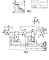
- FIG. 4 shows an embodiment illustrating the use for the voltage divider and for the battery of gain variation resistors with two integrated circuits LF 13006 from National Semiconductor.
- circuits essentially include a series of resistors between which one can connect thanks to 8 electronic switches controlled by a 3-bit decoder.
- the assembly can be followed by a low-pass filter F.
- FIG. 4 represents only a few power supplies + A and - A and omits to lighten the drawing a certain number of conventional components or connections not forming part of the invention.
- the output of amplifier A is also connected by a resistor R l to the input of filter F whose input + is grounded.
- On the input - of the filter F is also added via the resistor R 2 a negative voltage roughly adjusted by potentiometer P, which shifts up the signals at the output of F, ensuring that these signals will always be strictly positive, so that they can be effectively converted by the analog / digital converter.
- the resistors R 1 , R 2 and R 3 are chosen to be equal to each other and are taken from pins 13, 14 and 15 remaining available from the networks R G and D.
- the output of the filter F is connected to the analog / digital converter CA / N of FIG. 2 not shown in FIG. 4 which is followed by the microprocessor ⁇ P of FIG. 2 not shown in FIG. 4.
- the two integrated circuits are controlled by the microprocessor under the following conditions: their inputs 8, 9 and 10 receive the three selection bits D 0 , D 1 , D 2 , from the microprocessor, inputs 7 receiving the WR order gain (for R G ) or attenuation (for D V ) account the selection between gain or attenuation being controlled respectively by CS 1 or CS 2 .
- the beam WR, D 0 , D 1 , D 2 , CS 1 , CS 2 comes from the microprocessor ⁇ P.
- the PA preamplifier can be produced for example using a 3528 CM circuit from Burr-Brown, the amplifier A using a 547 KH and the filter F from an OP 07EH both from Analog Device.
- devices according to the invention find an application particularly well suited to the problems to be solved in the field of analysis by measuring the light transmission.
- the major difficulty resides in the measurement of the reactions of small amplitude, for which the absolute precision required on the ratio if between the signal i f delivered by the detector at i. end of reaction and the signal i i delivered by the start of reaction detector must be very good.
- any change in gain occurring during the course of the reaction is a source of error, even if the relationships between these gains are known, or have been measured beforehand, with the greatest possible accuracy.
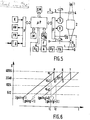
- FIG. 6 is an enlargement of FIG. 1 in a range of signals chosen by way of example.
- the initial value i i of the signal can in principle be measured on one or other of the three consecutive gains g i , g i + 1 , g i + 2 ' which would give respectively the three signal values S : a i , a i + 1 and a i + 2.
- the value a i measured on the gain g i gives in principle the best absolute measure of i. because the resolution on a i is better than a i + 1 and a i + 2 .
- the signal i f will be measured on the gain g i + 1 and will give the signal b i + 1 and the inevitable error due to the change in gain g i ⁇ g i + 1 will be reflected with a maximum effect maximum effect on the measure b i + 1 of the ratio i f. If by ai i if on the other hand care is taken to choose at the start the gain g i + 1 ' the value of S associated with i i will be a i + 1 and no error of gain change will affect the measurement b i + 1 from a i + 1 ratio i f . The case of an i must also be foreseen.
- the lamp 1 emits a light beam towards an optic 2, a disc 3 carrying filters 4 which, by rotation thanks to a motor 5, can insert a filter 4 on the beam path to ensure monochromatism or completely obscure the light beam in sight a measurement of black (from zero).
- the beam is concentrated on the analysis cell 6 and the unabsorbed light falls on the detector D followed by the preamplifier PA, the amplifier A and the other elements of FIG. 2.
- the cells 6 are shown on the rotor 7 driven by the motor 8, the assembly 6-7 can be placed in a thermostatically controlled enclosure 9.
- the microprocessor ⁇ P manages all of the operations: control of the rotation of the motor 8 of the rotor 7 and installation of the cells 6, control of the rotation of the motor 5 of the disc 3 and installation of the filters 4 for each cell, execution measurements with change in gain if the limit due to saturation or lack of resolution is reached ( Figure 6).
- the ⁇ P calculator can also select at regular intervals a particular position of the disc 3 which obscures the light beam and allows a periodic measurement of a black signal intended to correct by calculation a possible drift from zero.
- This ⁇ P microprocessor ensures in particular the calculation of concentrations from photometric measurements on the basis of Beer Lambert's law.
- the molecular extinction coefficients can moreover be in read-only or random-access memory.
- the temperature of the enclosure 9 is also controlled by the microprocessor ⁇ P thanks to the thermal probe 10 and to one or more sources of temperature readjustment.
- the appropriate interfaces are provided between the ⁇ P microprocessor and motors 5 and 8, probe 10 and temperature regulation devices.
- the microprocessor is connected to an internal memory IM, preferably partly dead (transformation logarithmic) and partly live (measurements and auto-calibration), as well as to an external EM read-only memory, for example a cassette, card or other medium of EPROM type, which contains the indications specific to the type of measurement to be carried out (disk 7 and cells 6, disk 3 and filters 4).
- IM preferably partly dead (transformation logarithmic) and partly live (measurements and auto-calibration)
- an external EM read-only memory for example a cassette, card or other medium of EPROM type, which contains the indications specific to the type of measurement to be carried out (disk 7 and cells 6, disk 3 and filters 4).
- the ⁇ P microprocessor is connected to various devices via IF interfaces: K input keyboard, AN alphanumeric display, PR printer, I / O input / output connection bus to other equipment.
Landscapes
- Physics & Mathematics (AREA)
- Theoretical Computer Science (AREA)
- Engineering & Computer Science (AREA)
- Biochemistry (AREA)
- General Physics & Mathematics (AREA)
- Spectroscopy & Molecular Physics (AREA)
- Health & Medical Sciences (AREA)
- Life Sciences & Earth Sciences (AREA)
- Chemical & Material Sciences (AREA)
- Analytical Chemistry (AREA)
- Nonlinear Science (AREA)
- General Health & Medical Sciences (AREA)
- Mathematical Physics (AREA)
- Immunology (AREA)
- Pathology (AREA)
- Investigating Or Analysing Materials By Optical Means (AREA)
- Analogue/Digital Conversion (AREA)
- Measurement Of The Respiration, Hearing Ability, Form, And Blood Characteristics Of Living Organisms (AREA)
- Investigating Or Analysing Biological Materials (AREA)
- Spectrometry And Color Measurement (AREA)
Priority Applications (1)
| Application Number | Priority Date | Filing Date | Title |
|---|---|---|---|
| AT86400943T ATE69680T1 (de) | 1985-05-06 | 1986-04-29 | Logarithmische wandler und ihre anwendung zur uebertragenen lichtmessung. |
Applications Claiming Priority (2)
| Application Number | Priority Date | Filing Date | Title |
|---|---|---|---|
| FR8506820A FR2581492B1 (fr) | 1985-05-06 | 1985-05-06 | Convertisseurs logarithmiques et leur application a la mesure de lumiere transmise |
| FR8506820 | 1985-05-06 |
Publications (2)
| Publication Number | Publication Date |
|---|---|
| EP0201415A1 true EP0201415A1 (de) | 1986-11-12 |
| EP0201415B1 EP0201415B1 (de) | 1991-11-21 |
Family
ID=9318972
Family Applications (1)
| Application Number | Title | Priority Date | Filing Date |
|---|---|---|---|
| EP86400943A Expired - Lifetime EP0201415B1 (de) | 1985-05-06 | 1986-04-29 | Logarithmische Wandler und ihre Anwendung zur übertragenen Lichtmessung |
Country Status (6)
| Country | Link |
|---|---|
| US (1) | US4905005A (de) |
| EP (1) | EP0201415B1 (de) |
| JP (1) | JPS6223623A (de) |
| AT (1) | ATE69680T1 (de) |
| DE (1) | DE3682530D1 (de) |
| FR (1) | FR2581492B1 (de) |
Cited By (3)
| Publication number | Priority date | Publication date | Assignee | Title |
|---|---|---|---|---|
| EP0350518A1 (de) * | 1988-07-12 | 1990-01-17 | Eppendorf-Netheler-Hinz Gmbh | Photometer |
| WO1992004775A1 (en) * | 1990-08-31 | 1992-03-19 | General Electric Company | Improved autozeroing apparatus and method for a computerized tomography data acquisition system |
| EP0495280A1 (de) * | 1991-01-18 | 1992-07-22 | International Business Machines Corporation | Analog-Digitalwandler mit Driftkompensation |
Families Citing this family (7)
| Publication number | Priority date | Publication date | Assignee | Title |
|---|---|---|---|---|
| TW234229B (de) * | 1992-10-26 | 1994-11-11 | Philips Electronics Nv | |
| US5724037A (en) * | 1995-05-23 | 1998-03-03 | Analog Devices, Inc. | Data acquisition system for computed tomography scanning and related applications |
| US5732002A (en) * | 1995-05-23 | 1998-03-24 | Analog Devices, Inc. | Multi-rate IIR decimation and interpolation filters |
| US5905398A (en) * | 1997-04-08 | 1999-05-18 | Burr-Brown Corporation | Capacitor array having user-adjustable, manufacturer-trimmable capacitance and method |
| US6331832B1 (en) * | 2000-04-03 | 2001-12-18 | Allen J. Rushing | Auto-ranging digital densitometer with lookup table |
| DE102005033919A1 (de) * | 2005-07-20 | 2007-01-25 | Conti Temic Microelectronic Gmbh | Verfahren und Vorrichtung Strommessung |
| CN111263885B (zh) * | 2017-09-19 | 2024-12-06 | 拜克门寇尔特公司 | 用于化学发光测量中的模拟光测量和光子计数的系统 |
Citations (8)
| Publication number | Priority date | Publication date | Assignee | Title |
|---|---|---|---|---|
| US3685047A (en) * | 1970-07-31 | 1972-08-15 | Sds Data Systems Inc | Seismic amplifiers |
| US3700871A (en) * | 1971-06-21 | 1972-10-24 | Shell Oil Co | Multiple multiplexer gain-ranging amplifier |
| FR2234709A1 (de) * | 1973-06-21 | 1975-01-17 | Sony Corp | |
| FR2378401A1 (fr) * | 1977-01-20 | 1978-08-18 | Cit Alcatel | Procede et dispositif pour adapter un signal analogique en vue de son codage numerique dans un codeur ayant une plage de codage donnee |
| US4300203A (en) * | 1979-10-19 | 1981-11-10 | Beckman Instruments, Inc. | Method and means for operating logarithmic circuits |
| GB2077537A (en) * | 1980-06-05 | 1981-12-16 | Avery Ltd W & T | Digitising circuitry |
| GB2116793A (en) * | 1982-03-03 | 1983-09-28 | Perkin Elmer Corp | Variable gain amplifier |
| EP0153719A2 (de) * | 1984-03-01 | 1985-09-04 | Honeywell Inc. | Verfahren und Gerät zur Verstärkungsregelung eines Verstärkersystems |
Family Cites Families (11)
| Publication number | Priority date | Publication date | Assignee | Title |
|---|---|---|---|---|
| US3530458A (en) * | 1965-10-28 | 1970-09-22 | Westinghouse Electric Corp | Analog to digital conversion system having improved accuracy |
| US3735393A (en) * | 1971-11-22 | 1973-05-22 | Bell Telephone Labor Inc | Self companding pulse code modulation systems |
| US3813609A (en) * | 1972-11-27 | 1974-05-28 | Petty Ray Geophysical Inc | Multiple stage sample normalizing amplifier with automatic gain prediction |
| DE7835541U1 (de) * | 1978-11-30 | 1979-03-29 | Alois Kober Kg, 8871 Koetz | Schräglenkerachsen für Fahrzeug-Anhänger, insbesondere für Wohnwagen |
| JPS5679946A (en) * | 1979-12-05 | 1981-06-30 | Dainippon Screen Mfg Co Ltd | Optical densitometer |
| JPS5737250A (en) * | 1980-08-18 | 1982-03-01 | Nippon Tectron Co Ltd | Colorimetric test method in clinical automatic chemical analysis |
| US4366469A (en) * | 1980-09-22 | 1982-12-28 | Ilc Data Device Corporation | Companding analog to digital converter |
| US4439038A (en) * | 1981-03-03 | 1984-03-27 | Sentrol Systems Ltd. | Method and apparatus for measuring and controlling the color of a moving web |
| US4467438A (en) * | 1982-01-18 | 1984-08-21 | Dset Laboratories, Inc. | Method and apparatus for determining spectral response and spectral response mismatch between photovoltaic devices |
| US4616329A (en) * | 1983-08-26 | 1986-10-07 | Bio-Rad Laboratories, Inc. | Self-calibrating adaptive ranging apparatus and method |
| US4616210A (en) * | 1984-09-14 | 1986-10-07 | The Perkin-Elmer Corporation | Spectrophotometers |
-
1985
- 1985-05-06 FR FR8506820A patent/FR2581492B1/fr not_active Expired - Lifetime
-
1986
- 1986-04-29 AT AT86400943T patent/ATE69680T1/de not_active IP Right Cessation
- 1986-04-29 DE DE8686400943T patent/DE3682530D1/de not_active Expired - Lifetime
- 1986-04-29 EP EP86400943A patent/EP0201415B1/de not_active Expired - Lifetime
- 1986-05-06 JP JP61103720A patent/JPS6223623A/ja active Pending
-
1988
- 1988-04-27 US US07/189,408 patent/US4905005A/en not_active Expired - Lifetime
Patent Citations (8)
| Publication number | Priority date | Publication date | Assignee | Title |
|---|---|---|---|---|
| US3685047A (en) * | 1970-07-31 | 1972-08-15 | Sds Data Systems Inc | Seismic amplifiers |
| US3700871A (en) * | 1971-06-21 | 1972-10-24 | Shell Oil Co | Multiple multiplexer gain-ranging amplifier |
| FR2234709A1 (de) * | 1973-06-21 | 1975-01-17 | Sony Corp | |
| FR2378401A1 (fr) * | 1977-01-20 | 1978-08-18 | Cit Alcatel | Procede et dispositif pour adapter un signal analogique en vue de son codage numerique dans un codeur ayant une plage de codage donnee |
| US4300203A (en) * | 1979-10-19 | 1981-11-10 | Beckman Instruments, Inc. | Method and means for operating logarithmic circuits |
| GB2077537A (en) * | 1980-06-05 | 1981-12-16 | Avery Ltd W & T | Digitising circuitry |
| GB2116793A (en) * | 1982-03-03 | 1983-09-28 | Perkin Elmer Corp | Variable gain amplifier |
| EP0153719A2 (de) * | 1984-03-01 | 1985-09-04 | Honeywell Inc. | Verfahren und Gerät zur Verstärkungsregelung eines Verstärkersystems |
Non-Patent Citations (2)
| Title |
|---|
| PATENTS ABSTRACTS OF JAPAN, vol. 5, no. 146 (P-80) [818], 16 septembre 1981; & JP - A - 56 79 946 (DAINIPPON SCREEN SEIZOU K.K.) 30-06-1981 * |
| PATENTS ABSTRACTS OF JAPAN, vol. 6, no. 104 (P-122) [982], 15 juin 1982, & JP - A - 57 37 250 (NIPPON TECTRON K.K.) 01-03-1982 * |
Cited By (5)
| Publication number | Priority date | Publication date | Assignee | Title |
|---|---|---|---|---|
| EP0350518A1 (de) * | 1988-07-12 | 1990-01-17 | Eppendorf-Netheler-Hinz Gmbh | Photometer |
| US5179379A (en) * | 1990-01-18 | 1993-01-12 | International Business Machines Corporation | Analog to digital convertor with drift compensation |
| WO1992004775A1 (en) * | 1990-08-31 | 1992-03-19 | General Electric Company | Improved autozeroing apparatus and method for a computerized tomography data acquisition system |
| US5177697A (en) * | 1990-08-31 | 1993-01-05 | General Electric Company | Autozeroing apparatus and method for a computerized tomography data acquisition system |
| EP0495280A1 (de) * | 1991-01-18 | 1992-07-22 | International Business Machines Corporation | Analog-Digitalwandler mit Driftkompensation |
Also Published As
| Publication number | Publication date |
|---|---|
| FR2581492B1 (fr) | 1990-02-23 |
| DE3682530D1 (de) | 1992-01-02 |
| US4905005A (en) | 1990-02-27 |
| EP0201415B1 (de) | 1991-11-21 |
| JPS6223623A (ja) | 1987-01-31 |
| ATE69680T1 (de) | 1991-12-15 |
| FR2581492A1 (fr) | 1986-11-07 |
Similar Documents
| Publication | Publication Date | Title |
|---|---|---|
| EP0201415B1 (de) | Logarithmische Wandler und ihre Anwendung zur übertragenen Lichtmessung | |
| Hernández | Fabry-perot interferometers | |
| US5014216A (en) | Concentration determination with multiple wavelength flash photometers | |
| EP0708317B1 (de) | Schnelles bichromatisches fiberoptisches Pyrometer | |
| EP0325499A1 (de) | Erfassungsgerät zur Digitalisierung von Hochdynamiksignalen | |
| Finkelstein et al. | Dust Extinction and metallicities of star-forming Lyα emitting galaxies at low redshift | |
| EP0762145B1 (de) | Pulsverarbeitungssystem für einen Gammateilchen-CdTe-Strahlungsdetektor | |
| WO1998019142A1 (fr) | Composant optique de modulation de polarisation, et son utilisation dans un polarimetre ou dans un ellipsometre | |
| FR2588656A1 (fr) | Appareil de spectro-colorimetrie a fibres optiques | |
| FR2474166A1 (fr) | Dispositif de mesure photometrique pour solutions complexes a bruit de fond variable | |
| Azadi et al. | The MOSDEF Survey: The Nature of Mid-infrared Excess Galaxies and a Comparison of IR and UV Star Formation Tracers at z∼ 2 | |
| WO2017220922A1 (fr) | Système de mesure et gyromètre comportant un tel système | |
| EP0406080A1 (de) | Verfahren und Gerät zur Erfassung und genauen Digitalisierung analoger Daten | |
| EP3019841A1 (de) | Vorrichtung zur kompensation des drifts einer phasenverschiebung einer vorrichtung zur modulierung des polarisationszustandes eines lichtstrahls | |
| FR2738928A1 (fr) | Amplificateur optique | |
| Peest et al. | Instrumentation-related uncertainty of reflectance and transmittance measurements with a two-channel spectrophotometer | |
| EP0921390A1 (de) | Verfahren zur Bestimmung der Konzentration eines Gases in einem Gasgemisch und Analysevorrichtung zur Durchführung dieses Verfahrens | |
| FR2951538A1 (fr) | Appareil de mesure spectrometrique de la diffusion inelastique de haute performance dans le domaine des basses frequences | |
| WO2020016259A1 (fr) | Méthode et dispositif de caractérisation de filtres optiques | |
| FR2525767A1 (fr) | Dispositif pour reduire des erreurs de mesure causees par lumiere parasite dans des spectrophotometres | |
| CN108680578B (zh) | 一种多光谱频分复用的检测系统及方法 | |
| FR2468917A1 (fr) | Dispositif variateur de niveau pour signaux numeriques | |
| Phan et al. | Circular multireflection cell for midinfrared laser spectroscopic trace gas analysis | |
| CN121761950A (zh) | 一种光学传感器检测量程的标定方法、装置、设备及介质 | |
| JP2000146693A (ja) | 光スペクトラム測定装置 |
Legal Events
| Date | Code | Title | Description |
|---|---|---|---|
| PUAI | Public reference made under article 153(3) epc to a published international application that has entered the european phase |
Free format text: ORIGINAL CODE: 0009012 |
|
| 17P | Request for examination filed |
Effective date: 19860505 |
|
| AK | Designated contracting states |
Kind code of ref document: A1 Designated state(s): AT BE CH DE GB IT LI LU NL SE |
|
| 17Q | First examination report despatched |
Effective date: 19891006 |
|
| GRAA | (expected) grant |
Free format text: ORIGINAL CODE: 0009210 |
|
| AK | Designated contracting states |
Kind code of ref document: B1 Designated state(s): AT BE CH DE GB IT LI LU NL SE |
|
| REF | Corresponds to: |
Ref document number: 69680 Country of ref document: AT Date of ref document: 19911215 Kind code of ref document: T |
|
| REF | Corresponds to: |
Ref document number: 3682530 Country of ref document: DE Date of ref document: 19920102 |
|
| ITF | It: translation for a ep patent filed | ||
| GBT | Gb: translation of ep patent filed (gb section 77(6)(a)/1977) | ||
| PLBE | No opposition filed within time limit |
Free format text: ORIGINAL CODE: 0009261 |
|
| STAA | Information on the status of an ep patent application or granted ep patent |
Free format text: STATUS: NO OPPOSITION FILED WITHIN TIME LIMIT |
|
| 26N | No opposition filed | ||
| EPTA | Lu: last paid annual fee | ||
| EAL | Se: european patent in force in sweden |
Ref document number: 86400943.6 |
|
| REG | Reference to a national code |
Ref country code: GB Ref legal event code: IF02 |
|
| PGFP | Annual fee paid to national office [announced via postgrant information from national office to epo] |
Ref country code: AT Payment date: 20050321 Year of fee payment: 20 |
|
| PGFP | Annual fee paid to national office [announced via postgrant information from national office to epo] |
Ref country code: SE Payment date: 20050323 Year of fee payment: 20 Ref country code: CH Payment date: 20050323 Year of fee payment: 20 |
|
| PGFP | Annual fee paid to national office [announced via postgrant information from national office to epo] |
Ref country code: NL Payment date: 20050325 Year of fee payment: 20 Ref country code: LU Payment date: 20050325 Year of fee payment: 20 Ref country code: GB Payment date: 20050325 Year of fee payment: 20 |
|
| PGFP | Annual fee paid to national office [announced via postgrant information from national office to epo] |
Ref country code: BE Payment date: 20050330 Year of fee payment: 20 |
|
| PGFP | Annual fee paid to national office [announced via postgrant information from national office to epo] |
Ref country code: DE Payment date: 20050401 Year of fee payment: 20 |
|
| PGFP | Annual fee paid to national office [announced via postgrant information from national office to epo] |
Ref country code: IT Payment date: 20050427 Year of fee payment: 20 |
|
| PG25 | Lapsed in a contracting state [announced via postgrant information from national office to epo] |
Ref country code: GB Free format text: LAPSE BECAUSE OF EXPIRATION OF PROTECTION Effective date: 20060428 |
|
| PG25 | Lapsed in a contracting state [announced via postgrant information from national office to epo] |
Ref country code: NL Free format text: LAPSE BECAUSE OF EXPIRATION OF PROTECTION Effective date: 20060429 |
|
| REG | Reference to a national code |
Ref country code: GB Ref legal event code: PE20 |
|
| REG | Reference to a national code |
Ref country code: CH Ref legal event code: PL |
|
| EUG | Se: european patent has lapsed | ||
| NLV7 | Nl: ceased due to reaching the maximum lifetime of a patent |
Effective date: 20060429 |
|
| BE20 | Be: patent expired |
Owner name: *INOVELF Effective date: 20060429 |