EP0201430A2 - Gasisolierter Leistungsschalter mit Lichtbogenbeblasung - Google Patents
Gasisolierter Leistungsschalter mit Lichtbogenbeblasung Download PDFInfo
- Publication number
- EP0201430A2 EP0201430A2 EP86400989A EP86400989A EP0201430A2 EP 0201430 A2 EP0201430 A2 EP 0201430A2 EP 86400989 A EP86400989 A EP 86400989A EP 86400989 A EP86400989 A EP 86400989A EP 0201430 A2 EP0201430 A2 EP 0201430A2
- Authority
- EP
- European Patent Office
- Prior art keywords
- blowing
- hollow part
- disjunction
- tube
- gas
- Prior art date
- Legal status (The legal status is an assumption and is not a legal conclusion. Google has not performed a legal analysis and makes no representation as to the accuracy of the status listed.)
- Withdrawn
Links
- 238000005422 blasting Methods 0.000 title 1
- 238000007664 blowing Methods 0.000 claims abstract description 27
- 238000004891 communication Methods 0.000 claims abstract description 8
- 238000010891 electric arc Methods 0.000 claims abstract description 3
- 238000000034 method Methods 0.000 description 2
- 238000005507 spraying Methods 0.000 description 2
- 230000005540 biological transmission Effects 0.000 description 1
- 230000006835 compression Effects 0.000 description 1
- 238000007906 compression Methods 0.000 description 1
- 230000017525 heat dissipation Effects 0.000 description 1
- 238000004519 manufacturing process Methods 0.000 description 1
- 230000009467 reduction Effects 0.000 description 1
Images

Classifications
-
- H—ELECTRICITY
- H01—ELECTRIC ELEMENTS
- H01H—ELECTRIC SWITCHES; RELAYS; SELECTORS; EMERGENCY PROTECTIVE DEVICES
- H01H33/00—High-tension or heavy-current switches with arc-extinguishing or arc-preventing means
- H01H33/60—Switches wherein the means for extinguishing or preventing the arc do not include separate means for obtaining or increasing flow of arc-extinguishing fluid
- H01H33/64—Switches wherein the means for extinguishing or preventing the arc do not include separate means for obtaining or increasing flow of arc-extinguishing fluid wherein the break is in gas
-
- H—ELECTRICITY
- H01—ELECTRIC ELEMENTS
- H01H—ELECTRIC SWITCHES; RELAYS; SELECTORS; EMERGENCY PROTECTIVE DEVICES
- H01H33/00—High-tension or heavy-current switches with arc-extinguishing or arc-preventing means
- H01H33/70—Switches with separate means for directing, obtaining, or increasing flow of arc-extinguishing fluid
- H01H33/88—Switches with separate means for directing, obtaining, or increasing flow of arc-extinguishing fluid the flow of arc-extinguishing fluid being produced or increased by movement of pistons or other pressure-producing parts
- H01H33/90—Switches with separate means for directing, obtaining, or increasing flow of arc-extinguishing fluid the flow of arc-extinguishing fluid being produced or increased by movement of pistons or other pressure-producing parts this movement being effected by or in conjunction with the contact-operating mechanism
- H01H33/901—Switches with separate means for directing, obtaining, or increasing flow of arc-extinguishing fluid the flow of arc-extinguishing fluid being produced or increased by movement of pistons or other pressure-producing parts this movement being effected by or in conjunction with the contact-operating mechanism making use of the energy of the arc or an auxiliary arc
-
- H—ELECTRICITY
- H01—ELECTRIC ELEMENTS
- H01H—ELECTRIC SWITCHES; RELAYS; SELECTORS; EMERGENCY PROTECTIVE DEVICES
- H01H33/00—High-tension or heavy-current switches with arc-extinguishing or arc-preventing means
- H01H33/70—Switches with separate means for directing, obtaining, or increasing flow of arc-extinguishing fluid
- H01H33/88—Switches with separate means for directing, obtaining, or increasing flow of arc-extinguishing fluid the flow of arc-extinguishing fluid being produced or increased by movement of pistons or other pressure-producing parts
Definitions
- the present invention relates to the breaking chamber of an arc blast gas circuit breaker.
- circuit breakers used in substations and in substations also require an increase in their circuit breaker capacity as well as high reliability.
- To increase the reliability of a circuit breaker it is important to reduce the number of spare parts and to simplify its mechanism. To this end, reductions in the number of switch points have been planned. Therefore, it is necessary to increase the breaking capacity of each of the points of the circuit breaker.
- the present invention aims, in view of the above considerations, to provide an arc blast gas circuit breaker which, by the efficient use of the heat energy of the arc released at the time of the tripping, allows obtain a high quality of disjunction, with a device of small size and a low motor energy.
- the present invention offers the characteristic of using, via the hollow part of the operating tube, the energy that the arc gives off at the start of the circuit breaker tripping operation, to introduce it into the blowing chamber and use it to reinforce the pressure rise in said chamber; in addition, at the end of the disjunction maneuver, use the hollow part of the maneuvering tube as a heat dissipation duct.
- An arc-blown gas circuit breaker comprising, in an insulating envelope of compressed gas, a fixed assembly and a movable assembly, a blast chamber placed in the movable assembly and constituted by a blowing piston and of a blowing cylinder compressing the gas which then passes through a nozzle and will cool and extinguish the electric arc produced between the fixed and movable arcing contacts, characterized in that orifices (5a) have been drilled in the hollow part (5b) of the operating tube (5) which actuates said cylinder (6), and put in communication, at the start of the disjunction maneuver, said blowing chamber (11) and the hollow part of said tube, and at the end of disjunction maneuver, they put said envelope into communication with the hollow part of the tube.
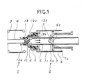
- 1 is the fixed contact assembly, consisting of a fixed arcing contact (4) and a fixed contact (which lets current flow through) - (3).
- 2 is the movable contact assembly composed of a hollow operating tube (5) to which a blowing cylinder (6) is fixed, a movable arcing contact (8), a movable arcing contact (which lets through the current) (9), an insulating nozzle (10).
- the blowing cylinder (6) of the movable assembly (2) forms, with the blowing piston (7) which is attached to the fixed part (invisible in the figure), the blowing (11).
- the orifices (5a) which connect the hollow part (5b) of the operating tube (5) and its external part, are made in such a way that, as shown in FIG. 1, they also put the interior (11) of the blowing chamber into communication with the hollow part (5b) of said tube (5), at the start of the disjunction maneuver.
- these orifices (5a) are formed so as to protrude, at the end of the disjunction maneuver, the head (7a) of the blowing piston (7) and thus to put the surrounding gas space in communication with the interior (5b) of the operating tube (5).
- a protuberance (5c) deflector
- Figure 1 shows the conditions at the start of the disjunction maneuver.
- the arc (13) produces great heat, but since the nozzle (10) is not yet sufficiently open, the capacity for tripping is zero.
- the orifices (5a) of the operating tube have not yet protruded from the head (7a) of the blowing piston (7), and they are in communication with the interior (11) of the blowing chamber.
- the orifices (5a) project beyond the head (7a) of the piston (7) and are in communication with the medium. Also there. is the hollow part (5b) of the operating tube (5) released in the surrounding gas and the heat emanating from the emitted arc. Under such conditions, the nozzle being already sufficiently open, the electric current can trip. As the heat trapped in the chamber (11) is almost uniformly dispersed in the cylinder, the rise in high pressure can continue until the end of the disjunction action. Consequently, the spraying, for a long time, of very rapid gas flow makes it possible to obtain a high quality of disjunction.
Landscapes
- Circuit Breakers (AREA)
Applications Claiming Priority (2)
| Application Number | Priority Date | Filing Date | Title |
|---|---|---|---|
| JP96001/85 | 1985-05-08 | ||
| JP9600185 | 1985-05-08 |
Publications (2)
| Publication Number | Publication Date |
|---|---|
| EP0201430A2 true EP0201430A2 (de) | 1986-12-17 |
| EP0201430A3 EP0201430A3 (de) | 1989-03-08 |
Family
ID=14152870
Family Applications (1)
| Application Number | Title | Priority Date | Filing Date |
|---|---|---|---|
| EP86400989A Withdrawn EP0201430A3 (de) | 1985-05-08 | 1986-05-07 | Gasisolierter Leistungsschalter mit Lichtbogenbeblasung |
Country Status (8)
| Country | Link |
|---|---|
| US (1) | US4665289A (de) |
| EP (1) | EP0201430A3 (de) |
| JP (1) | JPH0797466B2 (de) |
| KR (1) | KR890004057B1 (de) |
| DK (1) | DK213786A (de) |
| ES (1) | ES297033Y (de) |
| GR (1) | GR861187B (de) |
| PT (1) | PT82542B (de) |
Cited By (5)
| Publication number | Priority date | Publication date | Assignee | Title |
|---|---|---|---|---|
| DE4015179A1 (de) * | 1990-05-11 | 1991-11-14 | Licentia Gmbh | Kompressionsschalter |
| FR2763172A1 (fr) * | 1997-05-07 | 1998-11-13 | Gec Alsthom T & D Sa | Disjoncteur avec un systeme mecanique a tiroir pour chambre de coupure a course de compression reduite |
| RU2150764C1 (ru) * | 1999-08-23 | 2000-06-10 | Государственное унитарное предприятие "Всероссийский электротехнический институт им. В.И. Ленина" | Газовый выключатель |
| US8044318B2 (en) | 2007-10-03 | 2011-10-25 | Areva T&D Sa | Interrupting chamber of a circuit-breaker having two compression volumes |
| EP4492418A1 (de) * | 2023-07-10 | 2025-01-15 | Ampere SAS | Abschaltvorrichtung für einen elektrischen strom, batteriemodul mit einer solchen vorrichtung und kraftfahrzeug mit einem solchen batteriemodul |
Families Citing this family (11)
| Publication number | Priority date | Publication date | Assignee | Title |
|---|---|---|---|---|
| JPH03269924A (ja) * | 1990-03-19 | 1991-12-02 | Hitachi Ltd | ガス遮断器 |
| JP3281528B2 (ja) * | 1996-02-09 | 2002-05-13 | 株式会社日立製作所 | ガス遮断装置 |
| JP4660407B2 (ja) * | 2006-03-27 | 2011-03-30 | 株式会社東芝 | ガス絶縁開閉器 |
| JP6157824B2 (ja) | 2012-09-28 | 2017-07-05 | 株式会社東芝 | ガス遮断器 |
| JPWO2014171208A1 (ja) * | 2013-04-18 | 2017-02-16 | 株式会社日立製作所 | ガス遮断器 |
| JP6289856B2 (ja) | 2013-10-16 | 2018-03-07 | 株式会社東芝 | ガス遮断器 |
| KR101763451B1 (ko) * | 2014-04-09 | 2017-08-01 | 현대일렉트릭앤에너지시스템(주) | 아크열을 재이용하는 복합소호형 차단기 |
| KR101657454B1 (ko) * | 2014-09-25 | 2016-09-21 | 현대중공업 주식회사 | 가스절연 차단기 |
| EP3618088A1 (de) * | 2018-08-30 | 2020-03-04 | ABB Schweiz AG | Düse für hoch- oder mittelspannungsschalter |
| CN115206704A (zh) * | 2022-08-17 | 2022-10-18 | 中国南方电网有限责任公司超高压输电公司检修试验中心 | 灭弧室及直流高速开关 |
| CN120847572A (zh) * | 2025-09-11 | 2025-10-28 | 西安高压电器研究院股份有限公司 | 一种电弧试验装置及电弧试验方法 |
Family Cites Families (7)
| Publication number | Priority date | Publication date | Assignee | Title |
|---|---|---|---|---|
| JPS4844308A (de) * | 1971-10-08 | 1973-06-26 | ||
| CH645754A5 (en) * | 1979-06-14 | 1984-10-15 | Sprecher & Schuh Ag | Gas-blast circuit breaker |
| CH648432A5 (en) * | 1979-10-18 | 1985-03-15 | Sprecher & Schuh Ag | Gas-blast circuit breaker |
| JPS56159950U (de) * | 1980-04-30 | 1981-11-28 | ||
| DE8125211U1 (de) * | 1981-08-27 | 1985-03-21 | Siemens AG, 1000 Berlin und 8000 München | Elektrischer Schalter |
| US4440997A (en) * | 1982-05-28 | 1984-04-03 | Brown Boveri Electric Inc. | Puffer interrupter with arc energy assist |
| ATE32286T1 (de) * | 1983-11-15 | 1988-02-15 | Sprecher Energie Ag | Druckgasschalter. |
-
1986
- 1986-04-29 US US06/857,178 patent/US4665289A/en not_active Expired - Fee Related
- 1986-05-07 DK DK213786A patent/DK213786A/da not_active Application Discontinuation
- 1986-05-07 GR GR861187A patent/GR861187B/el unknown
- 1986-05-07 JP JP61103111A patent/JPH0797466B2/ja not_active Expired - Lifetime
- 1986-05-07 EP EP86400989A patent/EP0201430A3/de not_active Withdrawn
- 1986-05-07 KR KR8603545A patent/KR890004057B1/ko not_active Expired
- 1986-05-08 ES ES1986297033U patent/ES297033Y/es not_active Expired - Fee Related
- 1986-05-08 PT PT82542A patent/PT82542B/pt not_active IP Right Cessation
Cited By (6)
| Publication number | Priority date | Publication date | Assignee | Title |
|---|---|---|---|---|
| DE4015179A1 (de) * | 1990-05-11 | 1991-11-14 | Licentia Gmbh | Kompressionsschalter |
| FR2763172A1 (fr) * | 1997-05-07 | 1998-11-13 | Gec Alsthom T & D Sa | Disjoncteur avec un systeme mecanique a tiroir pour chambre de coupure a course de compression reduite |
| RU2150764C1 (ru) * | 1999-08-23 | 2000-06-10 | Государственное унитарное предприятие "Всероссийский электротехнический институт им. В.И. Ленина" | Газовый выключатель |
| US8044318B2 (en) | 2007-10-03 | 2011-10-25 | Areva T&D Sa | Interrupting chamber of a circuit-breaker having two compression volumes |
| EP4492418A1 (de) * | 2023-07-10 | 2025-01-15 | Ampere SAS | Abschaltvorrichtung für einen elektrischen strom, batteriemodul mit einer solchen vorrichtung und kraftfahrzeug mit einem solchen batteriemodul |
| FR3151131A1 (fr) * | 2023-07-10 | 2025-01-17 | Renault | Dispositif de coupure pour un courant électrique, module de batterie comprenant un tel dispositif et véhicule automobile muni d’un tel module |
Also Published As
| Publication number | Publication date |
|---|---|
| JPS62276717A (ja) | 1987-12-01 |
| DK213786A (da) | 1986-11-09 |
| PT82542A (fr) | 1986-06-01 |
| US4665289A (en) | 1987-05-12 |
| KR860009453A (ko) | 1986-12-23 |
| PT82542B (pt) | 1993-01-29 |
| ES297033Y (es) | 1990-03-16 |
| EP0201430A3 (de) | 1989-03-08 |
| JPH0797466B2 (ja) | 1995-10-18 |
| GR861187B (en) | 1986-09-09 |
| DK213786D0 (da) | 1986-05-07 |
| ES297033U (es) | 1989-09-01 |
| KR890004057B1 (en) | 1989-10-18 |
Similar Documents
| Publication | Publication Date | Title |
|---|---|---|
| EP0239068A1 (de) | Druckgasschalter | |
| EP0367072B1 (de) | Hochspannungsdruckgasschalter | |
| EP0591039B1 (de) | Hochspannung selbst-Blaslastscharter mit Schnittkammer mit reduzierter Gaskompression | |
| JPH0797466B2 (ja) | パッファ形ガスしゃ断器 | |
| EP0359224B1 (de) | Hochspannungsschalter mit gasförmigem Dielektrikum zum Beblasen | |
| CA2006934C (fr) | Disjoncteur a haute et moyenne tension a gaz de soufflage | |
| CA1099318A (en) | Circuit interrupter comprising arc-quenching fluid pressure boosting chamber | |
| EP0004213A1 (de) | Lichtbogenlöscheinrichtung mit pneumatischer und magnetischer Blasung | |
| US5155313A (en) | Medium tension circuit-breaker | |
| US4322591A (en) | Circuit breaker with means for producing a flow of arc-extinguishing gas | |
| JP2523480B2 (ja) | パツフア形ガスしや断器 | |
| FR2575323A1 (fr) | Disjoncteur a gaz comprime | |
| RU2091891C1 (ru) | Высоковольтный газовый выключатель с автогенерацией дугогасящего потока | |
| GB2332566A (en) | Electrical circuit breaker | |
| FR2623657A1 (fr) | Disjoncteur a autosoufflage par expansion de gaz isolant, equipe d'un ecran de repartition de champ electrique | |
| RU2153205C1 (ru) | Дугогасительное устройство высоковольтного газонаполненного автокомпрессионного выключателя | |
| FR2949170A1 (fr) | Chambre de coupure pour disjoncteur a moyenne ou haute tension a energie de manœuvre reduite | |
| JP2557363B2 (ja) | パツフア形ガス遮断器 | |
| JPH06196057A (ja) | ガス遮断器 | |
| JPH0367431A (ja) | パッファ形ガス遮断器 | |
| JPH0797468B2 (ja) | パツフア形ガス遮断器 | |
| EP0101371A1 (de) | Elektrischer Schalter mit rotierendem Lichtbogen | |
| JPH0750583B2 (ja) | パツフア形ガスしや断器 | |
| FR2460537A1 (fr) | Interrupteur a soufflage pneumatique de l'arc par expansion thermique des gaz de soufflage | |
| EP1139701A1 (de) | Plasmabrenner mit Elektrode/Düse-Kontaktstarter |
Legal Events
| Date | Code | Title | Description |
|---|---|---|---|
| PUAI | Public reference made under article 153(3) epc to a published international application that has entered the european phase |
Free format text: ORIGINAL CODE: 0009012 |
|
| AK | Designated contracting states |
Kind code of ref document: A2 Designated state(s): BE DE FR GB IT LU NL |
|
| PUAB | Information related to the publication of an a document modified or deleted |
Free format text: ORIGINAL CODE: 0009199EPPU |
|
| RA1 | Application published (corrected) |
Date of ref document: 19861217 Kind code of ref document: A2 |
|
| PUAL | Search report despatched |
Free format text: ORIGINAL CODE: 0009013 |
|
| AK | Designated contracting states |
Kind code of ref document: A3 Designated state(s): BE DE FR GB IT LU NL |
|
| RAP1 | Party data changed (applicant data changed or rights of an application transferred) |
Owner name: GEC ALSTHOM SA |
|
| STAA | Information on the status of an ep patent application or granted ep patent |
Free format text: STATUS: THE APPLICATION IS DEEMED TO BE WITHDRAWN |
|
| 18D | Application deemed to be withdrawn |
Effective date: 19891106 |
|
| RIN1 | Information on inventor provided before grant (corrected) |
Inventor name: YANABU, SATORU Inventor name: SUZUKI, KATSUMI Inventor name: MIZOGUCHI, HITOSHI Inventor name: IKEDA, HISATOSHI |