EP0201439B1 - Vorrichtung zur Belüftung eines Raums mit automatischer Veränderung des aus der Küche entnommenen Anteils - Google Patents
Vorrichtung zur Belüftung eines Raums mit automatischer Veränderung des aus der Küche entnommenen Anteils Download PDFInfo
- Publication number
- EP0201439B1 EP0201439B1 EP86420119A EP86420119A EP0201439B1 EP 0201439 B1 EP0201439 B1 EP 0201439B1 EP 86420119 A EP86420119 A EP 86420119A EP 86420119 A EP86420119 A EP 86420119A EP 0201439 B1 EP0201439 B1 EP 0201439B1
- Authority
- EP
- European Patent Office
- Prior art keywords
- shutter
- rod
- opening
- ventilator
- kitchen
- Prior art date
- Legal status (The legal status is an assumption and is not a legal conclusion. Google has not performed a legal analysis and makes no representation as to the accuracy of the status listed.)
- Expired
Links
- 238000009423 ventilation Methods 0.000 claims abstract description 7
- 238000000605 extraction Methods 0.000 claims description 15
- 238000010438 heat treatment Methods 0.000 claims description 4
- 230000004048 modification Effects 0.000 description 3
- 238000012986 modification Methods 0.000 description 3
- 238000004804 winding Methods 0.000 description 3
- 239000012141 concentrate Substances 0.000 description 2
- 238000012423 maintenance Methods 0.000 description 2
- 238000000034 method Methods 0.000 description 2
- 241001080024 Telles Species 0.000 description 1
- 230000000903 blocking effect Effects 0.000 description 1
- 239000003990 capacitor Substances 0.000 description 1
- 238000009833 condensation Methods 0.000 description 1
- 230000005494 condensation Effects 0.000 description 1
- 238000010276 construction Methods 0.000 description 1
- 239000003517 fume Substances 0.000 description 1
- 238000009413 insulation Methods 0.000 description 1
- 235000012054 meals Nutrition 0.000 description 1
- 230000007935 neutral effect Effects 0.000 description 1
- 235000019645 odor Nutrition 0.000 description 1
- 238000007789 sealing Methods 0.000 description 1
- XLYOFNOQVPJJNP-UHFFFAOYSA-N water Substances O XLYOFNOQVPJJNP-UHFFFAOYSA-N 0.000 description 1
Images


Classifications
-
- F—MECHANICAL ENGINEERING; LIGHTING; HEATING; WEAPONS; BLASTING
- F16—ENGINEERING ELEMENTS AND UNITS; GENERAL MEASURES FOR PRODUCING AND MAINTAINING EFFECTIVE FUNCTIONING OF MACHINES OR INSTALLATIONS; THERMAL INSULATION IN GENERAL
- F16K—VALVES; TAPS; COCKS; ACTUATING-FLOATS; DEVICES FOR VENTING OR AERATING
- F16K31/00—Actuating devices; Operating means; Releasing devices
- F16K31/44—Mechanical actuating means
- F16K31/52—Mechanical actuating means with crank, eccentric, or cam
- F16K31/524—Mechanical actuating means with crank, eccentric, or cam with a cam
- F16K31/52408—Mechanical actuating means with crank, eccentric, or cam with a cam comprising a lift valve
- F16K31/52441—Mechanical actuating means with crank, eccentric, or cam with a cam comprising a lift valve with a pivoted disc or flap
-
- F—MECHANICAL ENGINEERING; LIGHTING; HEATING; WEAPONS; BLASTING
- F24—HEATING; RANGES; VENTILATING
- F24F—AIR-CONDITIONING; AIR-HUMIDIFICATION; VENTILATION; USE OF AIR CURRENTS FOR SCREENING
- F24F11/00—Control or safety arrangements
- F24F11/70—Control systems characterised by their outputs; Constructional details thereof
- F24F11/72—Control systems characterised by their outputs; Constructional details thereof for controlling the supply of treated air, e.g. its pressure
- F24F11/74—Control systems characterised by their outputs; Constructional details thereof for controlling the supply of treated air, e.g. its pressure for controlling air flow rate or air velocity
- F24F11/745—Control systems characterised by their outputs; Constructional details thereof for controlling the supply of treated air, e.g. its pressure for controlling air flow rate or air velocity the air flow rate increasing with an increase of air-current or wind pressure
-
- F—MECHANICAL ENGINEERING; LIGHTING; HEATING; WEAPONS; BLASTING
- F24—HEATING; RANGES; VENTILATING
- F24F—AIR-CONDITIONING; AIR-HUMIDIFICATION; VENTILATION; USE OF AIR CURRENTS FOR SCREENING
- F24F7/00—Ventilation
- F24F7/04—Ventilation with ducting systems, e.g. by double walls; with natural circulation
- F24F7/06—Ventilation with ducting systems, e.g. by double walls; with natural circulation with forced air circulation, e.g. by fan positioning of a ventilator in or against a conduit
-
- F—MECHANICAL ENGINEERING; LIGHTING; HEATING; WEAPONS; BLASTING
- F24—HEATING; RANGES; VENTILATING
- F24F—AIR-CONDITIONING; AIR-HUMIDIFICATION; VENTILATION; USE OF AIR CURRENTS FOR SCREENING
- F24F7/00—Ventilation
- F24F2007/001—Ventilation with exhausting air ducts
- F24F2007/002—Junction box, e.g. for ducts from kitchen, toilet or bathroom
-
- F—MECHANICAL ENGINEERING; LIGHTING; HEATING; WEAPONS; BLASTING
- F24—HEATING; RANGES; VENTILATING
- F24F—AIR-CONDITIONING; AIR-HUMIDIFICATION; VENTILATION; USE OF AIR CURRENTS FOR SCREENING
- F24F13/00—Details common to, or for air-conditioning, air-humidification, ventilation or use of air currents for screening
- F24F13/08—Air-flow control members, e.g. louvres, grilles, flaps or guide plates
- F24F13/10—Air-flow control members, e.g. louvres, grilles, flaps or guide plates movable, e.g. dampers
- F24F13/14—Air-flow control members, e.g. louvres, grilles, flaps or guide plates movable, e.g. dampers built up of tilting members, e.g. louvre
- F24F2013/1493—Air-flow control members, e.g. louvres, grilles, flaps or guide plates movable, e.g. dampers built up of tilting members, e.g. louvre using an elastic membrane
Definitions
- the subject of the present invention is a device for ventilating premises, and in particular an individual dwelling house.
- a ventilation device generally comprises a motor-fan group placed in the attic of a house, making it possible to extract stale air from technical rooms, such as kitchens, bathrooms, WCs, in a permanent and constant manner, while the living and sleeping rooms are equipped with vents ensuring the admission of an outside air volume equal to the volume of air extracted in the technical rooms.
- a second solution consists in equipping the fan of a motor with a main sliding winding by using all or part of the winding to obtain the speed variation. If this device is cheaper than the previous one, the speed stability is much more random, especially when the supply voltage fluctuates.
- Another possibility is to have a motor at a speed with the possibility of reversing the direction of rotation to obtain two different curves, with an ambivalent wheel.
- the present invention aims to remedy these drawbacks by providing a device of simple design, reliable operation, economical construction, automatically allowing an increase in the flow rate extracted in the kitchen.
- the opening of the box intended for the connection of the tubing opening into the kitchen is equipped with a flap associated with elastic means tending to maneuver it towards its closed position, this flap being equipped with a member cooperating with a guide comprising two stops corresponding to the two values of opening of the shutter and two other stops offset relative to each other, both corresponding to the closed position of the shutter, the finger guide being shaped such that the flap being in the closed position and the finger pressing against the bottom of the first closing stop, the depression created by the fan tending to open the flap brings the finger in abutment against the first opening stop, the shutdown of the fan after which the shutter returns to the closed position brings the finger in abutment against the second closing abutment, the starting of the fan tending to open the flap brings the finger in abutment against the second
- the flap being in its position corresponding to the normal extraction regime, it suffices to switch to the maximum extraction regime in the kitchen, to stop the motor-fan then to restart it. The same maneuver makes it possible to return from the maximum extraction regime to the normal extraction regime.
- This technique is advantageous from an economic point of view, because if this device can operate with fans with two rotational speeds or with reverse direction, it can also operate with a fan with a single rotational speed.
- the means ensuring the maintenance of the flap, associated with the opening connected to the air extraction duct from the kitchen, in its two positions, and the passage from one position to the other are constituted by a lever located on the side of the inside or outside of the box, one end of which is articulated on the flap around an axis parallel to the axis of articulation of the flap and the l 'other end is equipped with a finger parallel to the axis of articulation thereof on the flap, engaged in a light forming a guide.
- the guide light of the shutter control finger is formed by an imprint of generally triangular shape, one of the sides substantially parallel to the plane of the opening intended to be closed by the shutter, comprises two separate recesses one of the 'other by a spout forming the two finger closing stops, the central part of the triangle having a rib inclined relative to the side in which the recesses are formed, one end of this rib being located opposite the first recess and the other end of the latter comprising a recess forming the pre first opening stop opening opposite the wall of the spout partly defining the second recess, the second opening stop being constituted by the third apex of the imprint.
- the finger Given the respective positions of the recesses forming stops and ramps, the finger can only move in the light, depending on the stops and starts of the fan, only according to a well-defined circuit.
- the shutter associated with the opening of the box connected to the kitchen is integral with a lever carrying shutters intended to come to close completely or partially the openings of the box connected to the other technical parts, when the shutter is in the open position. maximum.
- This arrangement makes it possible, by increasing the passage section of the extracted air in the kitchen and by reducing the passage section of the extracted air in the other technical rooms, to concentrate a large part of the extracted flow rate in the kitchen, this which is particularly advantageous because it allows the extraction of a large flow rate in the kitchen without the need for a motor-fan of high flow rate and power.
- the fan control means are such that the user does not have to stop, for a period of time which could be indefinite, the ventilation group.
- the electrical supply circuit of the fan motor comprises a contact blade which can be actuated on opening by a push button towards a position in which it is held in the open position by a bimetallic strip, associated with a resistance, the bimetallic strip ensuring the maintenance of the blade in the open position of the electrical contact as long as it has not reached a predetermined temperature supplied by heating the resistor.
- the user just has to press the push button.
- the electric current supply remains cut off as long as the bimetallic strip is not deformed, the heating time sufficient to ensure this deformation can be chosen to be of the order of 10 to 15 seconds.
- the shutter will occupy an opening position different from the position before the power cut, which allows a modification of the flow rate extracted in the kitchen.
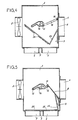
- Figure 1 shows a box (2) intended to be placed in the attic of a dwelling house, containing a motor not shown driving a fan (3).
- this box are formed three openings (4, 5 and 6) equipped with sleeves (7) allowing their connection to pipes, not shown, the other ends of which are connected to extraction outlets arranged respectively in the kitchen, a bathroom and toilet in the house.
- a shutter (8) articulated around a vertical axis constituted in the present case by an elastic blade (9) also ensuring the return function of the shutter (8 ) in the closed position.
- a lever (12) whose other end is equipped with a finger (13) also vertical, engaged in a light (14) formed in the bottom of the box (2) or in a member capable of being fixed on said bottom.
- the guide lumen (14) consists of a generally triangular imprint, one side (15) of which is substantially parallel to the plane of the opening (4) intended to be closed by the flap (8) comprises two recesses (16, 17) separated from each other by a spout (18).
- the angle of the triangle opposite the wall (15) forms a recess (19).
- the central part of the imprint is occupied by a rib (20) inclined relative to the side (15) of the triangle, so that it is closer to the recess (16) than to the recess ( 17), this rib (20) having one end located opposite the recess (16), and another end, having a recess (22) located behind the recess (17), and opening facing the wall (23) partly defining the recess (17).
- the flexible blade (9) tends to pivot the volume (8) towards its closed position, so that the finger (13) of the lever (12) is either in the recess (16), or in the recess (17).
- the flap (8) tends to open, and the finger (13) is supported either in a recess (19) or in a recess (22).
- the flap In normal operating conditions, the flap is in the position shown in Figure 2, the finger (13) being supported in the recess (22). To increase the flow rate extracted in the kitchen, the user just has to stop the fan motor first. Under the action of the return of the blade (9), the flap (8) closes, and the finger (13) bearing against the wall (23) comes into the bottom of the recess (17). When the fan is restarted, the finger (13) moves in the groove serving as a guide and comes to bear in the bottom of the recess (19), position in which the flap (8) occupies a maximum opening as shown in Figure 5.
- the shutter (8) carries a lever (24) fitted with shutters (25), shaped so that, when the shutter (8) is in the maximum open position, as shown in Figure 5, the shutters (25) close the openings (5, 6) in order to concentrate the extraction of the flow on the kitchen.
- FIGs 7 and 8 show a motor power control device (26) ensuring the drive of the fan (3).
- the phase and neutral wires are designated by the references (27) and (28) respectively.
- a supply contact (29) is closed by a blade (30) associated with a push button (32). Under the action of the push button, the blade (30) can actuate a bimetallic strip (33) hooked against the end of a resistor (34) ensuring that the contact blade remains in the open position, as shown in Figure 8.
- This solution is interesting because it allows the user to change the operating regime by simply pressing a push button.
- the invention brings a great improvement to the existing technique by providing a device of simple design, since requiring only one motor at a speed of rotation, of practical use for the user, and extremely efficient.
- the invention is not limited to the sole embodiment of this device, described above.
- the shape of the guide track of the finger mounted at one end of the shutter control lever could be different.
Landscapes
- Engineering & Computer Science (AREA)
- General Engineering & Computer Science (AREA)
- Mechanical Engineering (AREA)
- Physics & Mathematics (AREA)
- Fluid Mechanics (AREA)
- Chemical & Material Sciences (AREA)
- Combustion & Propulsion (AREA)
- Ventilation (AREA)
- Air-Flow Control Members (AREA)
- Structures Of Non-Positive Displacement Pumps (AREA)
Claims (10)
und dass die Führungsanordnung (14) des Fingers (13) so ausgebildet ist,
Priority Applications (1)
| Application Number | Priority Date | Filing Date | Title |
|---|---|---|---|
| AT86420119T ATE38281T1 (de) | 1985-05-07 | 1986-05-06 | Vorrichtung zur belueftung eines raums mit automatischer veraenderung des aus der kueche entnommenen anteils. |
Applications Claiming Priority (2)
| Application Number | Priority Date | Filing Date | Title |
|---|---|---|---|
| FR8507324 | 1985-05-07 | ||
| FR8507324A FR2581740B1 (fr) | 1985-05-07 | 1985-05-07 | Dispositif de ventilation d'un local, avec variation automatique du debit extrait dans la cuisine |
Publications (2)
| Publication Number | Publication Date |
|---|---|
| EP0201439A1 EP0201439A1 (de) | 1986-12-17 |
| EP0201439B1 true EP0201439B1 (de) | 1988-10-26 |
Family
ID=9319273
Family Applications (1)
| Application Number | Title | Priority Date | Filing Date |
|---|---|---|---|
| EP86420119A Expired EP0201439B1 (de) | 1985-05-07 | 1986-05-06 | Vorrichtung zur Belüftung eines Raums mit automatischer Veränderung des aus der Küche entnommenen Anteils |
Country Status (4)
| Country | Link |
|---|---|
| EP (1) | EP0201439B1 (de) |
| AT (1) | ATE38281T1 (de) |
| DE (1) | DE3661046D1 (de) |
| FR (1) | FR2581740B1 (de) |
Families Citing this family (13)
| Publication number | Priority date | Publication date | Assignee | Title |
|---|---|---|---|---|
| FR2682462B1 (fr) * | 1991-10-14 | 1993-12-03 | Michel Roussel | Dispositif de controle de la depression utile d'extraction d'une installation de ventilation mecanique controlee. |
| FR2685455B1 (fr) * | 1991-12-19 | 1997-04-11 | Claude Grandvuinet | Perfectionnements apportes aux appareils pour la ventilation mecanique des locaux. |
| FR2738329B1 (fr) * | 1995-09-01 | 1997-11-21 | Nather Diffusion | Groupe d'extraction d'air comportant au moins un organe de regulation et d'obturation |
| FR2754591B1 (fr) * | 1996-10-14 | 1998-12-11 | Cerga | Entree d'air pour dispositif de ventilation d'air d'un local |
| FR2828557B1 (fr) * | 2001-08-07 | 2003-10-10 | A C V I | Groupe de ventilation mecanique commande par pressostat |
| FR2850450B1 (fr) * | 2003-01-29 | 2005-04-29 | Atlantic C V I | Groupe de ventilation mecanique controlee |
| FR2855251A1 (fr) * | 2003-05-19 | 2004-11-26 | Atlantic C V I | Dispositif de repartition de debit pour ventilation mecanique controlee |
| FR2888304B1 (fr) * | 2005-07-08 | 2007-10-12 | Soler Et Palau | Piquage de ventilation et caisson de ventilation mecanique controle comportant un tel piquage |
| PL389227A1 (pl) * | 2009-10-08 | 2011-04-11 | Awenta E.W.A Chomka Spółka Jawna | Układ wentylacyjny |
| FR2955919A1 (fr) * | 2010-02-04 | 2011-08-05 | Atlantic Climatisation Et Ventilation | Dispositif de repartition d'un debit d'air, installation de ventilation et procede de regulation d'une telle installation |
| GB2530035A (en) * | 2014-09-09 | 2016-03-16 | Intelligent Energy Ltd | Microvalve |
| CN105841334B (zh) * | 2016-05-30 | 2022-03-15 | 上海洗尘环保科技有限公司 | 一种内外循环可控型空气净化器 |
| ES3000071T3 (en) * | 2022-04-27 | 2025-02-27 | Soler & Palau Res Sl | Controlled mechanical ventilation unit |
Family Cites Families (8)
| Publication number | Priority date | Publication date | Assignee | Title |
|---|---|---|---|---|
| FR1344040A (fr) * | 1963-01-09 | 1963-11-22 | Dispositif d'aération notamment pour fenêtres ou portes | |
| FR1417323A (fr) * | 1964-10-01 | 1965-11-12 | Cie Thermor | Perfectionnements aux aérateurs |
| FR1507329A (fr) * | 1966-11-17 | 1967-12-29 | Cepem | Aérateur perfectionné |
| DE2138538C2 (de) * | 1971-08-02 | 1973-10-04 | Maico Elektroapparate-Fabrik Gmbh, 7220 Schwenningen | Verschlußeinrichtung für Luft öffnungen oder dergleichen |
| FR2179517B1 (de) * | 1972-04-11 | 1976-06-11 | Etu Rech Ventilation | |
| FR2237133A1 (en) * | 1973-06-27 | 1975-02-07 | Tolerie Emaillerie Nantaise | Domestic ventilation system - solenoid opens flap in outlet duct for increased kitchen ventilation |
| DE2431066A1 (de) * | 1974-06-28 | 1976-01-15 | Maico Elektroapparate | Verschlusseinrichtung fuer lueftungskanaele oder dergleichen |
| US4372196A (en) * | 1981-03-30 | 1983-02-08 | Henderson Donald L | Insulating and draft preventing automatic shutter for attic and other exhaust type fans |
-
1985
- 1985-05-07 FR FR8507324A patent/FR2581740B1/fr not_active Expired
-
1986
- 1986-05-06 AT AT86420119T patent/ATE38281T1/de not_active IP Right Cessation
- 1986-05-06 EP EP86420119A patent/EP0201439B1/de not_active Expired
- 1986-05-06 DE DE8686420119T patent/DE3661046D1/de not_active Expired
Also Published As
| Publication number | Publication date |
|---|---|
| DE3661046D1 (en) | 1988-12-01 |
| FR2581740A1 (fr) | 1986-11-14 |
| FR2581740B1 (fr) | 1989-10-27 |
| ATE38281T1 (de) | 1988-11-15 |
| EP0201439A1 (de) | 1986-12-17 |
Similar Documents
| Publication | Publication Date | Title |
|---|---|---|
| EP0201439B1 (de) | Vorrichtung zur Belüftung eines Raums mit automatischer Veränderung des aus der Küche entnommenen Anteils | |
| FR2647510A1 (fr) | Dispositif de commande a distance pour installation d'aspiration centralisee | |
| FR2644053A2 (fr) | Bouilloire electrique perfectionnee | |
| FR2701202A1 (fr) | Dispositif pour commander l'évacuation de vapeur hors de la chambre de lavage d'un lave-vaisselle. | |
| FR2508606A1 (fr) | Procede de regulation de la ventilation d'un local et moyens pour sa mise en oeuvre | |
| CA2268810A1 (fr) | Appareil de cuisson electrique comportant un dispositif de condensation des vapeurs de cuisson | |
| FR2484692A1 (fr) | Dispositif pour couper automatiquement l'alimentation electrique d'un moteur et son utilisation | |
| EP0718861A1 (de) | Elektrischer Sicherheitsschalter | |
| CA2539352C (en) | Structure for connecting a dust collecting hose of a central vacuum cleaning system | |
| EP0011527A1 (de) | Konvektor | |
| EP0058933A1 (de) | Vorrichtung zur Temperatursteuerung und -regelung, insbesondere der Kühlflüssigkeit einer Brennkraftmaschine | |
| EP0867570B1 (de) | Einbauspülkasten zur Top- oder Frontbetätigung | |
| FR2931351A1 (fr) | Aspirateur | |
| EP1180648B1 (de) | Motorisierte Abzugshaube für Küchen | |
| FR2571477A1 (fr) | Installation de ventilation mecanique modulante | |
| FR2619438A3 (fr) | Dispositif de commande et de conduite de l'air sortant d'une installation de chauffage, d'aeration et de climatisation | |
| KR200294080Y1 (ko) | 양변기 자동배수장치 | |
| FR2595453A1 (fr) | Bouche de ventilation a debit variable | |
| FR2739116A1 (fr) | Reservoir de chasse a encastrer a commande par le dessus ou en facade | |
| CA1117256A (fr) | Bidet hygienique adaptable a un bol de toilette | |
| FR2590354A1 (fr) | Installation de ventilation perfectionnee | |
| CA1292103C (fr) | Cuvettes de cabinets d'aisance | |
| EP0269509B1 (de) | Gasventil mit integrierter Sicherheitsvorrichtung für Heisswassergerät ohne ständige Zündflamme | |
| EP0165175A2 (de) | Abzug und Lüftungsanlage, regelbar in Abhängigkeit von der Temperatur und dem Feuchtigkeitsgrad des Luftstroms | |
| FR2723889A1 (fr) | Commutateur de commande pour l'installation de chauffage et de climatisation d'un vehicule automobile |
Legal Events
| Date | Code | Title | Description |
|---|---|---|---|
| PUAI | Public reference made under article 153(3) epc to a published international application that has entered the european phase |
Free format text: ORIGINAL CODE: 0009012 |
|
| 17P | Request for examination filed |
Effective date: 19861006 |
|
| AK | Designated contracting states |
Kind code of ref document: A1 Designated state(s): AT BE CH DE GB IT LI LU NL SE |
|
| PUAB | Information related to the publication of an a document modified or deleted |
Free format text: ORIGINAL CODE: 0009199EPPU |
|
| PUAF | Information related to the publication of a search report (a3 document) modified or deleted |
Free format text: ORIGINAL CODE: 0009199SEPU |
|
| R17D | Deferred search report published (corrected) |
Effective date: 19861217 |
|
| RA1 | Application published (corrected) |
Date of ref document: 19861217 Kind code of ref document: A1 |
|
| 17Q | First examination report despatched |
Effective date: 19870402 |
|
| ITF | It: translation for a ep patent filed | ||
| GRAA | (expected) grant |
Free format text: ORIGINAL CODE: 0009210 |
|
| AK | Designated contracting states |
Kind code of ref document: B1 Designated state(s): AT BE CH DE GB IT LI LU NL SE |
|
| REF | Corresponds to: |
Ref document number: 38281 Country of ref document: AT Date of ref document: 19881115 Kind code of ref document: T |
|
| GBT | Gb: translation of ep patent filed (gb section 77(6)(a)/1977) | ||
| REF | Corresponds to: |
Ref document number: 3661046 Country of ref document: DE Date of ref document: 19881201 |
|
| PLBE | No opposition filed within time limit |
Free format text: ORIGINAL CODE: 0009261 |
|
| STAA | Information on the status of an ep patent application or granted ep patent |
Free format text: STATUS: NO OPPOSITION FILED WITHIN TIME LIMIT |
|
| 26N | No opposition filed | ||
| PGFP | Annual fee paid to national office [announced via postgrant information from national office to epo] |
Ref country code: SE Payment date: 19910320 Year of fee payment: 6 Ref country code: BE Payment date: 19910320 Year of fee payment: 6 |
|
| PGFP | Annual fee paid to national office [announced via postgrant information from national office to epo] |
Ref country code: LU Payment date: 19910404 Year of fee payment: 6 |
|
| PGFP | Annual fee paid to national office [announced via postgrant information from national office to epo] |
Ref country code: CH Payment date: 19910416 Year of fee payment: 6 |
|
| ITTA | It: last paid annual fee | ||
| PGFP | Annual fee paid to national office [announced via postgrant information from national office to epo] |
Ref country code: NL Payment date: 19910531 Year of fee payment: 6 Ref country code: AT Payment date: 19910531 Year of fee payment: 6 |
|
| EPTA | Lu: last paid annual fee | ||
| PG25 | Lapsed in a contracting state [announced via postgrant information from national office to epo] |
Ref country code: LU Free format text: LAPSE BECAUSE OF NON-PAYMENT OF DUE FEES Effective date: 19920506 Ref country code: AT Effective date: 19920506 |
|
| PG25 | Lapsed in a contracting state [announced via postgrant information from national office to epo] |
Ref country code: SE Effective date: 19920507 |
|
| PG25 | Lapsed in a contracting state [announced via postgrant information from national office to epo] |
Ref country code: LI Effective date: 19920531 Ref country code: CH Effective date: 19920531 Ref country code: BE Effective date: 19920531 |
|
| BERE | Be: lapsed |
Owner name: ALDES ATELIERS LYONNAIS D'EMBOUTISSAGE SPECIAL Effective date: 19920531 |
|
| PG25 | Lapsed in a contracting state [announced via postgrant information from national office to epo] |
Ref country code: NL Effective date: 19921201 |
|
| NLV4 | Nl: lapsed or anulled due to non-payment of the annual fee | ||
| REG | Reference to a national code |
Ref country code: CH Ref legal event code: PL |
|
| PGFP | Annual fee paid to national office [announced via postgrant information from national office to epo] |
Ref country code: GB Payment date: 19940505 Year of fee payment: 9 |
|
| PGFP | Annual fee paid to national office [announced via postgrant information from national office to epo] |
Ref country code: DE Payment date: 19940524 Year of fee payment: 9 |
|
| EUG | Se: european patent has lapsed |
Ref document number: 86420119.9 Effective date: 19921204 |
|
| PG25 | Lapsed in a contracting state [announced via postgrant information from national office to epo] |
Ref country code: GB Effective date: 19950506 |
|
| GBPC | Gb: european patent ceased through non-payment of renewal fee |
Effective date: 19950506 |
|
| PG25 | Lapsed in a contracting state [announced via postgrant information from national office to epo] |
Ref country code: DE Effective date: 19960201 |
|
| PG25 | Lapsed in a contracting state [announced via postgrant information from national office to epo] |
Ref country code: IT Free format text: LAPSE BECAUSE OF NON-PAYMENT OF DUE FEES;WARNING: LAPSES OF ITALIAN PATENTS WITH EFFECTIVE DATE BEFORE 2007 MAY HAVE OCCURRED AT ANY TIME BEFORE 2007. THE CORRECT EFFECTIVE DATE MAY BE DIFFERENT FROM THE ONE RECORDED. Effective date: 20050506 |