EP0201467A1 - Linearer Schrittmotor - Google Patents
Linearer Schrittmotor Download PDFInfo
- Publication number
- EP0201467A1 EP0201467A1 EP86850117A EP86850117A EP0201467A1 EP 0201467 A1 EP0201467 A1 EP 0201467A1 EP 86850117 A EP86850117 A EP 86850117A EP 86850117 A EP86850117 A EP 86850117A EP 0201467 A1 EP0201467 A1 EP 0201467A1
- Authority
- EP
- European Patent Office
- Prior art keywords
- armature
- stator
- elements
- stepping motor
- pole teeth
- Prior art date
- Legal status (The legal status is an assumption and is not a legal conclusion. Google has not performed a legal analysis and makes no representation as to the accuracy of the status listed.)
- Withdrawn
Links
- 230000004907 flux Effects 0.000 claims abstract description 6
- 238000004804 winding Methods 0.000 claims description 27
- 239000000696 magnetic material Substances 0.000 claims description 5
- 230000001133 acceleration Effects 0.000 description 4
- 238000006073 displacement reaction Methods 0.000 description 3
- 230000000694 effects Effects 0.000 description 2
- XEEYBQQBJWHFJM-UHFFFAOYSA-N Iron Chemical group [Fe] XEEYBQQBJWHFJM-UHFFFAOYSA-N 0.000 description 1
- 230000001154 acute effect Effects 0.000 description 1
- 239000004411 aluminium Substances 0.000 description 1
- XAGFODPZIPBFFR-UHFFFAOYSA-N aluminium Chemical compound [Al] XAGFODPZIPBFFR-UHFFFAOYSA-N 0.000 description 1
- 229910052782 aluminium Inorganic materials 0.000 description 1
- 238000005219 brazing Methods 0.000 description 1
- 239000004020 conductor Substances 0.000 description 1
- 238000010276 construction Methods 0.000 description 1
- 230000017525 heat dissipation Effects 0.000 description 1
- 238000001208 nuclear magnetic resonance pulse sequence Methods 0.000 description 1
- 229910001220 stainless steel Inorganic materials 0.000 description 1
- 239000010935 stainless steel Substances 0.000 description 1
Images
Classifications
-
- H—ELECTRICITY
- H02—GENERATION; CONVERSION OR DISTRIBUTION OF ELECTRIC POWER
- H02K—DYNAMO-ELECTRIC MACHINES
- H02K41/00—Propulsion systems in which a rigid body is moved along a path due to dynamo-electric interaction between the body and a magnetic field travelling along the path
- H02K41/02—Linear motors; Sectional motors
- H02K41/03—Synchronous motors; Motors moving step by step; Reluctance motors
Definitions
- the present invention relates to a linear stepping motor including an armature and a stator, relative to which the armature is movably mounted, the stator having at least two stator elements with pole teeth rows extending in the direction of travel of the armature, the armature having armature elements with pole teeth rows arranged along the pole teeth rows of the stator elements for closing, in coactions, magnetic flux paths transverse the direction of armature travel, said pole teeth rows being mutually displaced such that when the pole teeth of one armature element are in register with the pole teeth of the corresponding stator element the pole teeth of the remaining armature elements are displaced in the direction of armature travel relative the pole teeth of the stator element corresponding to the respective armature element.
- Stepping motors may be used for accurate and exact movement of movable parts in machine tools, printers and other apparatus.
- printers it is also known to use a linear stepping motor with an armatur provided with magnetising windings for the linear movement of the printing head, the armature being mounted on the same carriage as the printing head.
- the armature elements will be short with consequently weak power.
- Another problem is also the limitation which the printing head-carrying armature of the stepping motor signifies for the acceleration capacity of the printing head, due to the weight of the iron cores and windings carried by the armature and the current supplying conductors to the windings which must also be moved.
- a general object of the invention has been to achieve a new design principle for stepping motors, which permits a considerable increase of the runner's acceleration capacity (high quotient force/mass).
- a particular object of the invention has also been to achieve a stepping motor structure allowing the use of a small and light armature without magnetising windings and which is well suited to such as driving a printing head.
- each stator element may have a substantially groove-shaped space extending in the direction of armature travel, the defining side walls of the groove between them accomodating the pole teeth rows facing towards each other of the stator element, while the armature may have an armature element in each groove-shaped space with a tooth row on each side of the armature element facing towards a corresponding one of the pole teeth rows of the stator element, the armature element being carried by a common carrying body (carriage) of non-magnetic material.
- the construction in accordance with the invention also allows in a simple manner the disposition of freely dimensionable stator windings in the longitudinal direction of the stator under the path of travel of the armature.
- the invention signifies that with give dimensions of the apparatus considerably greater power than was as previously been possible may be transferred to the armature.
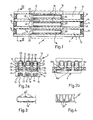
- the linear stepping motor illustrated in Figures 1 and 2a includes an armature generally denoted by 2, here designated runner, as well as a stator generally denoted by 4, relative to which the runner 2 is movably supported by the intermediary of suitable bearing means not illustrated in the Figures.
- these bearing means may comprise sliding bearings between the runner 2 and stator 4, but ball bearings are also conceivable, of course. The more specific embodiment of these bearing means will be easily understood by one skilled in the art.
- the stator 4 is built up from three magnetising elements 6, 8 and 10, which are arranged mutually parallel and are essentially U-shaped in cross section.
- the legs of the intermediate magnetising element 8 are made integral with the respective adjacent legs of the elements 6 and 10 so that the total cross-sectional shape is obtained which may be clearly perceived from Figure 2a.
- the stator may comprise separate elements joined to each other side by side. From the free ends of the legs and approximately down to half their height there extend pole teeth on the inside of the legs, these teeth denoted by 12 in all three mangetising elements 6-10.
- the legs may thus suitably be projecting further out than the cross pieces 13, so that the windings 14 at the ends of the stator are recessed, as appears clearly from Figure 1.
- the windings 14 are also recessed on the underside of the stator in longitudinally extending grooves 15 in the stator or in a body, made from such as aluminium, fastened to the underside of the stator.
- the longitudinal portions of the windings 14 have been excluded from Figure 1.
- FIG. 2b An alternative arrangement of windings 14 is illustrated in Figure 2b. Two of the windings 14a and 14c are surrounding each one leg of the stator while the third winding 14b is surrounding two legs. This arrangement simplifies the assembling of the stator and its windings.
- Runner 2 contains a flat carrying body 16 of a non-magnetic material such as stainless steel, on the underside of which there are recessed three bar-like armature elements 18 of magnetic material, e.g. fastend by brazing.
- the carrying plate 16 is merely indicated by a dashed line in Figure 1 for the sake of clarity.
- the armature elements 18 are dimentioned such that transversely they extend with some play in the respective upper groove 19 of the stator 4 and thrust into the groove 19 to depth substantially corresponding to the width of the pole teeth 12.
- pole tooth width is intened here the dimension in the depth direction of the groove 19.
- the pole teeth 12 and 20 are made with the same pitch, although the pole teeth 12 of the magnetising elements 6, 8, 10 are successively displaced relative each other by one third of a tooth pitch from the stator element 6 to the stator element 8 to the stator element 10. Alternatively, there may be such a displacement between the armature elements, of course.
- the pole teeth 12 and 20 may have the same straight shape with the flanks extending at right angles to the travelling direction of the runner, but according to an alternative illutstrated in Figure 3 the pole teeth 20 of the anchor elements 18 may be helically cut so that their flanks extend in an acute angle to those of the pole teeth 12. In this way there is achieved in operation of the stepping motor an effect of the kind more closely described in the Swedish specification 7408952-5 in relative movement between the tooth rows 12 and 20. The same effect is achieved even if the flanks of the teeth 20 are at right angles to the travelling direction and the teeth 12 are helically cut.
- the windings 14 of the respective magnetising elements 6, 8, 10 have applied to them a magnetising current via drive pulses in a suitable sequency, so that a magnetic flux, indicated by closed freehand lines 22, occurs in the elements 6, 8, 10 one after the other.
- a magnetic force is thus induced alternatingly between the respective magnetising elements and the armature bars 18 running therein, thetinct of this force in the travelling direction of the runner causing it to move stepwise.
- the drive pulse sequences shall be suitably displaced a third of a period in relation to each other in correspondence to the above described displacement between the tooth rows 12.
- the armature or runner speed is reduced and increased by respectively reducing and increasing the drive pulse frequency and the runner direction of travel is determined by the commutation sequence.
- the present invention solves in an extremely advantageous way the problem of achieving a high acceleration and low weight of the runner combined with long travel. Furthermore, there is achieved good heat dissipation from the windings via the stator to the structure attached thereto, such as a fastening plate, d ue to the short heat conduction path.
- a stepping motor in accordance with the invention may vary considerably.
- a length of about 50 cm of the stator could be used, the modular implementation of the apparatus according to Figures 1 and 2 could thus be utilised, as necessary, to amount two or more such modules in register with each other for driving a common armature.
- Magnetising windings 14 lying in line with each other are then connected in series between the different modules. Parallel connection is also possible, but series connection gives an automatic voltage concentration to the module where the armature is, due to arising inductance conditions.
- the inactive modules i.e. those where the armature does not happen to be, then only take up the voltage corresponding to the respective leakage inductance and resistive voltage drop.
- the lengths of the modules may have an order of magnitude of several meters, with corresponding up-scaling of remaining dimensions.
- Such embodiments may be used for such as machine tools as of different sizes, apparatus for moving door members, etc.
Landscapes
- Engineering & Computer Science (AREA)
- Physics & Mathematics (AREA)
- Chemical & Material Sciences (AREA)
- Combustion & Propulsion (AREA)
- Electromagnetism (AREA)
- Power Engineering (AREA)
- Linear Motors (AREA)
Applications Claiming Priority (2)
| Application Number | Priority Date | Filing Date | Title |
|---|---|---|---|
| SE8502066A SE457043B (sv) | 1985-04-29 | 1985-04-29 | Linjaer stegmotor |
| SE8502066 | 1985-04-29 |
Publications (1)
| Publication Number | Publication Date |
|---|---|
| EP0201467A1 true EP0201467A1 (de) | 1986-11-12 |
Family
ID=20360002
Family Applications (1)
| Application Number | Title | Priority Date | Filing Date |
|---|---|---|---|
| EP86850117A Withdrawn EP0201467A1 (de) | 1985-04-29 | 1986-04-08 | Linearer Schrittmotor |
Country Status (4)
| Country | Link |
|---|---|
| US (1) | US4721873A (de) |
| EP (1) | EP0201467A1 (de) |
| JP (1) | JPS61254063A (de) |
| SE (1) | SE457043B (de) |
Families Citing this family (5)
| Publication number | Priority date | Publication date | Assignee | Title |
|---|---|---|---|---|
| US4864169A (en) * | 1985-09-27 | 1989-09-05 | Centre National De La Recherche Scientifique | Polyphase variable reluctance motor |
| US5389844A (en) * | 1990-11-06 | 1995-02-14 | Clever Fellows Innovation Consortium, Inc. | Linear electrodynamic machine |
| FR2785733B1 (fr) * | 1998-06-12 | 2004-07-02 | Toyoda Automatic Loom Works | Moteur lineaire |
| JP4708093B2 (ja) * | 2005-06-01 | 2011-06-22 | 山洋電気株式会社 | リニアモータ |
| US10560011B2 (en) * | 2015-05-07 | 2020-02-11 | Sikorsky Aircraft Corporation | Linear electromechanical actuators |
Citations (10)
| Publication number | Priority date | Publication date | Assignee | Title |
|---|---|---|---|---|
| CH283885A (de) * | 1948-12-01 | 1952-06-30 | Siemens Ag | Mechanisch regelbare Drehfeldasynchronmaschine mit ausgeprägten, tangential verstellbaren Polen und konzentrierten Polwicklungen. |
| FR2026353A1 (de) * | 1968-12-17 | 1970-09-18 | Nat Res Dev | |
| DE1613758A1 (de) * | 1967-01-25 | 1971-04-29 | Maurice Barthalon | Eine mechanische Wirkung ausuebende elektromagnetische Vorrichtung |
| US3699365A (en) * | 1970-08-12 | 1972-10-17 | Siemens Ag | Electrodynamic linear motor |
| US3881139A (en) * | 1973-11-16 | 1975-04-29 | Fujitsu Ltd | 3-Axis pulse operated linear motor |
| SE388738B (sv) * | 1970-03-11 | 1976-10-11 | Fujitsu Ltd | Linjer elektrisk stegmotor |
| SE390779B (sv) * | 1974-07-08 | 1977-01-17 | Facit Ab | Stegmotor, omfattande minst tva efter varandra, utefter en axel anordnade stator-rotorpar |
| US4075539A (en) * | 1975-08-15 | 1978-02-21 | Kokusai Denshin Denwa Kabushiki Kaisha | Step-by-step reciprocating mechanism |
| DE2826940A1 (de) * | 1977-06-24 | 1979-01-18 | Exxon Research Engineering Co | Hochleistungsschrittmotor |
| EP0134827A1 (de) * | 1983-09-08 | 1985-03-27 | Ibm Deutschland Gmbh | Elektromagnetischer Antrieb für fortlaufende und schrittweise Linear- oder Drehbewegungen |
Family Cites Families (5)
| Publication number | Priority date | Publication date | Assignee | Title |
|---|---|---|---|---|
| US3268747A (en) * | 1964-02-28 | 1966-08-23 | Superior Electric Co | Linear electric motor |
| DE2623234A1 (de) * | 1976-05-24 | 1977-12-01 | Alberto Kling | Elektromagnetische antriebsvorrichtung |
| JPS5725151A (en) * | 1980-07-22 | 1982-02-09 | Matsushita Electric Ind Co Ltd | Linear motor |
| US4504750A (en) * | 1982-04-21 | 1985-03-12 | Matsushita Electric Industrial Co., Ltd. | Linear motor |
| US4581553A (en) * | 1984-04-16 | 1986-04-08 | Helmut Moczala | Brushless DC motor, especially linear motor, having an increased force-to-velocity ratio |
-
1985
- 1985-04-29 SE SE8502066A patent/SE457043B/sv not_active IP Right Cessation
-
1986
- 1986-04-08 EP EP86850117A patent/EP0201467A1/de not_active Withdrawn
- 1986-04-16 US US06/852,636 patent/US4721873A/en not_active Expired - Fee Related
- 1986-04-28 JP JP61097006A patent/JPS61254063A/ja active Pending
Patent Citations (10)
| Publication number | Priority date | Publication date | Assignee | Title |
|---|---|---|---|---|
| CH283885A (de) * | 1948-12-01 | 1952-06-30 | Siemens Ag | Mechanisch regelbare Drehfeldasynchronmaschine mit ausgeprägten, tangential verstellbaren Polen und konzentrierten Polwicklungen. |
| DE1613758A1 (de) * | 1967-01-25 | 1971-04-29 | Maurice Barthalon | Eine mechanische Wirkung ausuebende elektromagnetische Vorrichtung |
| FR2026353A1 (de) * | 1968-12-17 | 1970-09-18 | Nat Res Dev | |
| SE388738B (sv) * | 1970-03-11 | 1976-10-11 | Fujitsu Ltd | Linjer elektrisk stegmotor |
| US3699365A (en) * | 1970-08-12 | 1972-10-17 | Siemens Ag | Electrodynamic linear motor |
| US3881139A (en) * | 1973-11-16 | 1975-04-29 | Fujitsu Ltd | 3-Axis pulse operated linear motor |
| SE390779B (sv) * | 1974-07-08 | 1977-01-17 | Facit Ab | Stegmotor, omfattande minst tva efter varandra, utefter en axel anordnade stator-rotorpar |
| US4075539A (en) * | 1975-08-15 | 1978-02-21 | Kokusai Denshin Denwa Kabushiki Kaisha | Step-by-step reciprocating mechanism |
| DE2826940A1 (de) * | 1977-06-24 | 1979-01-18 | Exxon Research Engineering Co | Hochleistungsschrittmotor |
| EP0134827A1 (de) * | 1983-09-08 | 1985-03-27 | Ibm Deutschland Gmbh | Elektromagnetischer Antrieb für fortlaufende und schrittweise Linear- oder Drehbewegungen |
Non-Patent Citations (1)
| Title |
|---|
| IBM TECHNICAL DISCLOSURE BULLETIN, vol 25, no 10 March 1983, pages 5177-5178, D.E. BOYD et al: "Printhead motor" * |
Also Published As
| Publication number | Publication date |
|---|---|
| SE8502066D0 (sv) | 1985-04-29 |
| SE457043B (sv) | 1988-11-21 |
| SE8502066L (sv) | 1986-10-30 |
| JPS61254063A (ja) | 1986-11-11 |
| US4721873A (en) | 1988-01-26 |
Similar Documents
| Publication | Publication Date | Title |
|---|---|---|
| US4839543A (en) | Linear motor | |
| KR101023564B1 (ko) | 리니어 모터 액튜에이터 | |
| US4788477A (en) | Linear motor-driven X-Y table | |
| US8067862B2 (en) | Linear motor actuator | |
| US6705408B2 (en) | Power tool with a linear motor | |
| GB1604267A (en) | Stepper motor | |
| IE50533B1 (en) | Linear dc permanent magnet motor | |
| JP3695542B2 (ja) | リニア電磁アクチュエータを具備したxy駆動装置 | |
| JPH0349554A (ja) | リニアモータ | |
| US5959415A (en) | Linear motor with improved coil design and heat removal | |
| US4721873A (en) | Linear stepping motor | |
| US4794284A (en) | Linear D.C. motor with non-ferrous stator core | |
| CN101278467B (zh) | 线性同步电动机以及线性电动机促动器 | |
| CN208489786U (zh) | 一种竖装平板直线电机 | |
| JPS5857066B2 (ja) | リニアモ−タ | |
| US20050140213A1 (en) | Linear motor armature and linear motor | |
| KR102120569B1 (ko) | 횡자속 리니어모터 | |
| KR0183284B1 (ko) | 무 브러시 직류 선형 구동 제어 시스템 | |
| ATE222421T1 (de) | Antriebsmittel für eine linearbewegung insbesondere kontinuierliche linearbewegung und langstator-linearmotor | |
| SU743135A1 (ru) | Линейный асинхронный двигатель | |
| JP2007082352A (ja) | リニアアクチュエータ | |
| SU1343511A1 (ru) | Линейный двигатель посто нного тока | |
| SU868942A1 (ru) | Линейный асинхронный двигатель | |
| US20090127941A1 (en) | Linear drive with a moving, reduced-mass and laterally guided passive unit | |
| SU1504748A1 (ru) | Линейный электродвигатель посто нного тока |
Legal Events
| Date | Code | Title | Description |
|---|---|---|---|
| PUAI | Public reference made under article 153(3) epc to a published international application that has entered the european phase |
Free format text: ORIGINAL CODE: 0009012 |
|
| AK | Designated contracting states |
Kind code of ref document: A1 Designated state(s): CH DE FR GB IT LI NL SE |
|
| 17P | Request for examination filed |
Effective date: 19861201 |
|
| RAP1 | Party data changed (applicant data changed or rights of an application transferred) |
Owner name: FACIT AKTIEBOLAG |
|
| 17Q | First examination report despatched |
Effective date: 19890609 |
|
| STAA | Information on the status of an ep patent application or granted ep patent |
Free format text: STATUS: THE APPLICATION IS DEEMED TO BE WITHDRAWN |
|
| 18D | Application deemed to be withdrawn |
Effective date: 19891020 |
|
| RIN1 | Information on inventor provided before grant (corrected) |
Inventor name: STENUDD, SVEN GUNNAR WALTER |