EP0201736A2 - Dispositif pour distribuer de l'engrais - Google Patents
Dispositif pour distribuer de l'engrais Download PDFInfo
- Publication number
- EP0201736A2 EP0201736A2 EP86105047A EP86105047A EP0201736A2 EP 0201736 A2 EP0201736 A2 EP 0201736A2 EP 86105047 A EP86105047 A EP 86105047A EP 86105047 A EP86105047 A EP 86105047A EP 0201736 A2 EP0201736 A2 EP 0201736A2
- Authority
- EP
- European Patent Office
- Prior art keywords
- vehicle
- fan
- blower
- axis
- hydraulic
- Prior art date
- Legal status (The legal status is an assumption and is not a legal conclusion. Google has not performed a legal analysis and makes no representation as to the accuracy of the status listed.)
- Granted
Links
Images


Classifications
-
- A—HUMAN NECESSITIES
- A01—AGRICULTURE; FORESTRY; ANIMAL HUSBANDRY; HUNTING; TRAPPING; FISHING
- A01M—CATCHING, TRAPPING OR SCARING OF ANIMALS; APPARATUS FOR THE DESTRUCTION OF NOXIOUS ANIMALS OR NOXIOUS PLANTS
- A01M9/00—Special adaptations or arrangements of powder-spraying apparatus for purposes covered by this subclass
- A01M9/0007—Pneumatic dusters
- A01M9/003—Pneumatic field dusters, e.g. self-propelled, drawn or tractor-mounted
-
- A—HUMAN NECESSITIES
- A01—AGRICULTURE; FORESTRY; ANIMAL HUSBANDRY; HUNTING; TRAPPING; FISHING
- A01C—PLANTING; SOWING; FERTILISING
- A01C15/00—Fertiliser distributors
- A01C15/04—Fertiliser distributors using blowers
-
- A—HUMAN NECESSITIES
- A01—AGRICULTURE; FORESTRY; ANIMAL HUSBANDRY; HUNTING; TRAPPING; FISHING
- A01C—PLANTING; SOWING; FERTILISING
- A01C19/00—Arrangements for driving working parts of fertilisers or seeders
- A01C19/02—Arrangements for driving working parts of fertilisers or seeders by a motor
Definitions
- the invention relates to a device for spreading fertilizer, consisting of a vehicle, for. B. a tractor, with a PTO shaft and a saddled or attached spreading unit, which has a storage container with outlet openings, dosing devices arranged underneath and a plurality of adjoining these with inlet openings, extending to both sides and perpendicular to the longitudinal axis of the vehicle, connected to a blower, that end at different distances from the vehicle's longitudinal axis at scattering openings with distributor elements.
- blower spreaders are used in particular for the large-scale spreading of fertilizers or similar bulk goods-like agricultural products. They can be used with large working widths of up to 18 m and more. For smaller to medium working widths, the complete spreader unit can be attached to the three-point linkage, for example of a tractor coupled, while with larger working widths, which also require larger storage containers,. this is separated from the spreading unit and saddled directly on the vehicle, while all other components of the spreading unit are coupled to the three-point linkage of the tractor (DE-PS 34 29.042.7). Instead, it is also possible to arrange the entire spreading unit with a large-volume storage container on a trailer (FR-OS 77 06 437).
- blower spreaders of this type require a maximum payload of fertilizer and, on the other hand, a short construction so that the steering ability and building accessibility of the vehicle do not suffer because the center of gravity of the spreading unit is too far back.
- These requirements in turn lead to the shortest possible construction and thus to extremely limited space, so that the coupling of the spreading unit and the inspection and maintenance of the components of the transmission chain is cumbersome and time-consuming.
- the invention has for its object to reduce the construction and maintenance costs for devices of the aforementioned construction and by reducing the weight Possibility of increasing the payload. Starting from the device mentioned at the outset, this object is achieved by a hydraulic motor which is seated directly on the axis of the fan rotor.
- the invention frees itself from the principle of coupling the spreader unit to the power take-off, which was customary in fan spreader systems, and instead proposes a hydraulic self-drive for the fan.
- Such hydraulic drives are characterized by lower construction costs and low weight. All components of the usual transmission chain between the PTO shaft and the axis of the fan rotor are omitted. This can significantly reduce the weight. Maintenance-intensive parts, such as shaft bearings, V-belts etc. and the associated source of interference are eliminated by the invention.
- the space requirement of a hydraulic motor is considerably less than that of the conventional drive, so that the space saved for increasing the payload is available. The cumbersome coupling to the PTO is no longer necessary.
- the hydraulic motor is connected via a line to a hydraulic pump, which in turn is coupled to the PTO shaft.
- the hydraulic motor is advantageously equipped with a return suction device which allows the fan rotor to run out when the PTO shaft is still. Furthermore, a control device for keeping the speed of the hydraulic motor constant can be provided independently of the PTO speed.
- the blower rotor is preferably made of plastic.
- the design of the drive according to the invention enables the fan to be arranged transversely to the direction of travel. Such a design is not possible in the conventional PTO drive or is only possible at an unacceptably high cost, (DE-OS 21 60 751), since this would require a Minkelgetriebc with appropriate bracket and additional space.
- the blower can be arranged upright (narrow design) or lying (flat, low-lying design). This results in the advantage that only little space is required in the direction of construction, ie in the width or height of the spreading unit, and the space saving is available for increasing the payload, while in the conventional arrangement the complete diameter of the blower is lost for the wide use of the storage container .
- the aforementioned embodiment also opens up the possibility that the blower can have a single pressure port which is connected to two air distributors, one of which is connected to the stray lines on one side of the vehicle's longitudinal axis.
- This results in a more favorable air distribution and space utilization in the commonly used tangential blowers, since only a single pressure port lying in the direction of travel is necessary, from which the air can be distributed to the scatter lines on both sides.
- the blower has two pressure ports, each with an air distributor for the stray lines on each side. In the conventional design, two pressure sockets and a long air deflection are necessary for at least one side for reasons of space saving and the streamlined air flow.
- the storage container has a floor that slopes down from the longitudinal axis of the vehicle to the outlet openings.
- the fan arranged with its axis transverse to the direction of travel, as is known per se, is arranged below the roof-shaped floor.
- the fan extends with its larger extension in the diameter direction either in the direction of travel or it is horizontally and transversely at the lowest possible point, so that the space below the floor remains largely free and the angle of inclination of the floor surfaces is correspondingly flatter and thus the payload in the storage container can be correspondingly larger.
- the design according to the invention with its smaller space requirement also gives the possibility of providing a blower for the scatter lines on each side of the longitudinal axis of the vehicle in order to avoid flow losses due to necessary deflections and to achieve the largest possible spread with the lowest possible hydraulic power.
- both fans can have a common axis on which the hydraulic motor is seated or can be provided with one hydraulic motor each, in which case both hydraulic motors run synchronously and ensure the same spreading power on both sides.
- both hydraulic motors run synchronously and ensure the same spreading power on both sides.
- Two identical blowers can be used, which are only installed the other way round, in order to obtain an opposite direction of rotation.
- the hydraulic motor can sit on the axis of only one fan rotor and the other can be driven via a spur gear, possibly with a reversal of the direction of rotation.
- the storage container with an outlet opening on both sides of the vehicle and dosing devices arranged underneath for the stray lines on each side of the vehicle, sits on the vehicle itself, while the remaining components of the spreader unit, in particular the stray lines and the blower, are on one Frame are arranged, which in turn to the three-point linkage of the vehicle is coupled.
- a lifting frame can be arranged on the frame.
- a further pressure line leads under the reservoir on the vehicle and via air distributors to the metering elements around the fertilizer escaping, each via a pneumatic delivery line to a stray line feed the lifting frame.
- the blower is not only used to distribute the fertilizer, but also for intermediate conveying and must therefore provide a large conveying capacity with the appropriate size.
- the pressure line (s) for the intermediate conveyance must have a length and also guide means in order to bridge the distance between the storage container and the blower and, moreover, to be able to follow the relative movement between these (lifting movement of the three-point linkage and the lifting frame).
- this structure can be considerably simplified in that a separate conveying fan is provided for the pneumatic conveying lines, which is hydraulically driven and arranged on the vehicle.
- the spreading fan follows the movements of the spreading unit so that the air flow and the spreading power always remain the same regardless of the height of the spreading unit.
- the weight of the spreading unit seated on the three-point linkage is considerably reduced and thus the overall center of gravity is favorably forward shifted.
- the blower spreader described above has the outlet connection of the blower or the rear blower near the innermost distribution elements on the scattering lines, so that, not least because of the high suction power, there is a risk that the escaping fertilizer particles, whirled up dust etc. will also be sucked in will. In the design according to the invention, this can easily be avoided by the smaller space requirement and the greater freedom of movement in the arrangement of the spreading fan.
- the conveying fan can be connected to the hydraulic network of the vehicle, since it can have a relatively low power consumption, which only has to be sufficient to convey the fertilizer straight into the scatter lines, where it can arrive with relatively low kinetic energy.
- a conveying blower with hydraulic drive or connection can be provided for the pneumatic conveying lines on each side of the vehicle.
- separately controllable hydraulic circuits can be provided for the conveying fan (s) and also for the scatter fan (s).
- a tachometer is expediently provided at least for the blowers for the scatter lines and a tachometer is arranged on the vehicle. This is particularly advantageous when the speed of the hydraulic motor is adjustable, for example to adapt the blower output to different spreading widths.
- a pressure display instrument can be arranged on the vehicle as a control device and behind the hydraulic pump a pressure relief valve as a speed limitation and safety device.
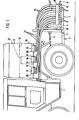
- FIGS. 1 and 2 The device shown in FIGS. 1 and 2 is largely the subject of the unpublished patent application P 34 29 042 and is therefore described below:
- a large-volume storage container 2 On the bed of a vehicle 1, for. B. a system tractor, a large-volume storage container 2 is saddled, which receives the grit.
- the system tractor also has a three-point linkage 3 consisting of two lower links 4 and one.
- the spreading unit 7 consists in a conventional manner of a plurality of scatter lines 8 arranged in parallel next to one another, which extend in bundles from the longitudinal axis of the vehicle and open out at distribution points 9 at different distances.
- These distribution elements consist, for example, of baffle plates, which are arranged in front of the openings of the scatter lines bent backwards.
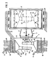
- the spreading unit also has a blower 11 (FIG. 2) on whose axis 12 running in the direction of travel sits a hydraulic motor 17 which is coupled to a hydraulic pump 15 on the PTO shaft (not shown) of the system tractor or to its hydraulic network.
- the blower 11 has a pressure connection 13 which leads to an air distributor 14 which extends over the entire width of the scatter lines 8 on a vehicle side and distributes the air to the individual scatter lines.
- a further fan 11a sits in parallel, which works via a pressure connection 13a and an air distributor 14a on the stray lines 8 on the other side of the vehicle.
- the blower 11a can have its own hydraulic motor 17a.
- the scatter lines 8 each have an injector (not shown), above which a box 16, which is guided over all lines, is arranged for the purpose of the spreading material.
- the stray lines 8 can be folded up about an axis (not shown) into a transport position and at the same time folded into shorter packages with a relatively low height.
- the saddle tank 2 saddled on the system tractor has a floor 29 (FIG. 1) sloping roof-shaped on both sides of the longitudinal axis of the vehicle and outlet openings arranged in each case near the side boundary of the storage tank, in the area of which metering elements 18 are mounted in the form of axially parallel cam wheels. Below the metering elements 18, metering bowls 19 are arranged under resilient contact with the metering elements, via which the metered spreading material arrives in collecting bowls 20.
- Each drip tray 20 belongs to a pneumatic delivery line 21, the number of delivery lines corresponding to the number of scatter lines 8. So it is the delivery lines 21 of each container side, as from Figures 2 and 3 can be seen, assigned to the scatter lines 8 of the scattering unit 7 on the corresponding vehicle side. In the exemplary embodiment shown, three delivery lines are assigned to each metering element, which accordingly lead to three stray lines.
- the delivery lines each have an injector (not shown) in the area of the collecting trays 20, an air distributor 23 being connected upstream of all the injectors on one side of the vehicle and connected to the pressure port 24 of a delivery blower 25 with a drive 22 (see FIG. 2) . Otherwise, the delivery lines 21, as shown in FIG. 1, are guided to the rear of the spreading unit 7. There they have a downwardly curved section 26 bridging the level difference and adjoining vertical sections 27 which then open into the feed box 16 above the injectors at the scatter lines 8.
- the frame 6 of the spreading unit 7 is connected to a crossbar of the three-point linkage 3 via a self-aligning bearing 28 arranged in the longitudinal axis of the vehicle, so that the entire spreading unit 7 can oscillate around the bearing 28. If a higher lifting height of the spreading unit than is possible with the three-point linkage 3 is desired for late fertilization, then a lifting frame can be assigned to the frame 6, which can be shifted in height with the spreading unit 7.
- the storage container 2 and the spreading unit 7 can also be used in the same way in conjunction with a self-propelled vehicle or a trailer, provided that the trailer has appropriate coupling options with lifting devices. When saddling onto a trailer, it can be fitted with maintenance tires (large diameter, narrow width).
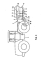
- FIGS. 3 to 9 show an embodiment of the device in several modifications, which is intended in particular for small to medium spreads.
- the reservoir 2 has, as in. 1 and 2, a floor 29 sloping downward from the longitudinal axis of the vehicle and having outlet openings at the deepest point, including metering elements and below, in turn, inlet openings, as is similar with reference to FIG. 1 in connection with the one placed there Storage containers 2 have been described.
- two scatter blowers 11, 11a are in turn arranged on a common axis 12 lying in the direction of travel, on which the hydraulic motor 17 is seated, which in the exemplary embodiment according to FIG. 3 is operated by a hydraulic pump 15 coupled to the PTO shaft 30.
- the line 31 is used to connect the hydraulic pump 15 to the hydraulic motor 17, while the return line 32 opens into a hydraulic tank 33 from which the hydraulic fluid is sucked in by the hydraulic pump 15 via the line 34.
- the hydraulic tank 33 is 7-mounted on the frame 6 of the spreading unit.
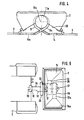
- Fig. 4 shows the arrangement from the front side, from which it is particularly clear that the pressure ports 13, 13a can be arranged in fluidically and in terms of space most favorable training and the space below the roof-shaped floor 29 is not obstructed, so that there is good accessibility .
- Fig. 5 shows a modified embodiment in which two fans 35, 36 are arranged one behind the other, the rotor of which are seated on aligned axes.
- the hydraulic motor 17 is assigned to the blower 35, while the blower 36 located behind in the direction of travel has its own hydraulic motor 37, which is also connected to the hydraulic pump 15.
- These blowers 35, 36 work via a respective pressure connection 13, 13a, to an air distributor 14, 14a, to which the stray lines 8 on one side of the vehicle are connected.
- blowers 11, 11a - similar to the embodiment according to FIG. 3 - are arranged in the vehicle axle and a hydraulic motor 17, 17a is placed on each of their axles.
- the blowers 11, 11a in turn each have a pressure connection 13, 13a, which goes out to one side, to which an air distributor 14 14a is connected.
- the hydraulic motors 17, 17a are connected directly to the local hydraulic network of the vehicle 1 via one or each via a pressure line 38 and a return line 39. In this case, the PTO 30 of the vehicle 1 remains free.
- the outlet connections 40, 41 are also indicated. Both fans are absolutely identical and are only set against each other so that the fan rotors rotate in opposite directions.
- Figure 7 shows an embodiment in which the rotor of both fans is arranged transversely to the direction of travel, in this case with a vertical axis 42, so that the fan rotor and the fan housing lie with their diametrical dimension in a horizontal plane.
- the blower can be arranged at the lowest possible point of the spreading unit, so that the roof-shaped floor can run as flat as the angle of repose of the spreading material allows.
- the pressure ports 13, 13a are attached at approximately opposite points, to which in turn an air distributor 14, 14a connects.
- On the blower axis 42 as in the previously described embodiments, there is one or each hydraulic motor 17, which in this embodiment is also connected directly to the hydraulic system of the vehicle 1 via a pressure line 38 and a return line 39.
- a single blower 11 is provided, which is arranged below the roof-shaped bottom of the storage container 2.
- the fan rotor sits on a horizontal axis 12 running transversely to the direction of travel, so that the fan housing and the fan rotor extend with their largest diametrical dimension in the direction of travel, whereby the space below the roof-shaped floor is best utilized.
- the blower has only a short pressure port, not recognizable in FIG. 8, to which an air distributor 1 4 is connected on each side.
- a single blower 11 - similar to the embodiment according to FIG. 3 - is arranged in the vehicle axis and the hydraulic motor 17 is placed on the blower axis.
- the blower 11 has outgoing pressure connections 13 on both sides, to each of which an air distributor 14 connects.
- the hydraulic motor 17 is connected directly to the local hydraulic network of the vehicle 1 via a pressure line 38 and a return line 39.
- the PTO 30 of the vehicle 1 remains free.
- the axis of the blower arranged horizontally and transversely to the direction of travel, as in the embodiments shown, it is also possible to arrange only one blower transversely or both blowers with different transverse axes (horizontal and vertical).
Landscapes
- Life Sciences & Earth Sciences (AREA)
- Environmental Sciences (AREA)
- Soil Sciences (AREA)
- Engineering & Computer Science (AREA)
- Insects & Arthropods (AREA)
- Pest Control & Pesticides (AREA)
- Wood Science & Technology (AREA)
- Zoology (AREA)
- Fertilizing (AREA)
Applications Claiming Priority (4)
| Application Number | Priority Date | Filing Date | Title |
|---|---|---|---|
| DE3513739 | 1985-04-17 | ||
| DE3513737 | 1985-04-17 | ||
| DE19853513737 DE3513737A1 (de) | 1985-04-17 | 1985-04-17 | Vorrichtung zum streuen von duenger |
| DE19853513739 DE3513739A1 (de) | 1985-04-17 | 1985-04-17 | Vorrichtung zum streuen von duenger |
Publications (4)
| Publication Number | Publication Date |
|---|---|
| EP0201736A2 true EP0201736A2 (fr) | 1986-11-20 |
| EP0201736A3 EP0201736A3 (en) | 1986-12-10 |
| EP0201736B1 EP0201736B1 (fr) | 1990-10-10 |
| EP0201736B2 EP0201736B2 (fr) | 1994-01-19 |
Family
ID=25831412
Family Applications (1)
| Application Number | Title | Priority Date | Filing Date |
|---|---|---|---|
| EP86105047A Expired - Lifetime EP0201736B2 (fr) | 1985-04-17 | 1986-04-12 | Dispositif pour distribuer de l'engrais |
Country Status (2)
| Country | Link |
|---|---|
| EP (1) | EP0201736B2 (fr) |
| DE (1) | DE3674832D1 (fr) |
Cited By (1)
| Publication number | Priority date | Publication date | Assignee | Title |
|---|---|---|---|---|
| EP0282812A3 (fr) * | 1987-03-11 | 1988-12-28 | Amazonen-Werke H. Dreyer GmbH & Co. KG | Système hydraulique pour entraíner un épandeur |
Family Cites Families (6)
| Publication number | Priority date | Publication date | Assignee | Title |
|---|---|---|---|---|
| DE2226605A1 (de) * | 1972-05-31 | 1973-12-13 | Josef Gail | Mischwerk fuer duengemittel |
| US3911650A (en) * | 1974-01-02 | 1975-10-14 | Donald F Johnson | Hay loading apparatus |
| DE2425091A1 (de) * | 1974-05-24 | 1975-11-27 | Leo L Tompkins | Druckmittelmotor |
| FR2382171A1 (fr) * | 1977-03-04 | 1978-09-29 | Nodet Gougis | Epandeur pneumatique a rampes d'epandage pivotantes |
| JPS5877905A (ja) * | 1981-09-02 | 1983-05-11 | プル−テク・リミテツド | 液圧制御弁 |
| DE3325430C2 (de) * | 1983-07-14 | 1987-03-26 | Rauch Landmaschinenfabrik GmbH, 7573 Sinzheim | Vorrichtung zum Streuen von schüttfähigem Gut |
-
1986
- 1986-04-12 DE DE8686105047T patent/DE3674832D1/de not_active Expired - Lifetime
- 1986-04-12 EP EP86105047A patent/EP0201736B2/fr not_active Expired - Lifetime
Cited By (1)
| Publication number | Priority date | Publication date | Assignee | Title |
|---|---|---|---|---|
| EP0282812A3 (fr) * | 1987-03-11 | 1988-12-28 | Amazonen-Werke H. Dreyer GmbH & Co. KG | Système hydraulique pour entraíner un épandeur |
Also Published As
| Publication number | Publication date |
|---|---|
| EP0201736B1 (fr) | 1990-10-10 |
| DE3674832D1 (de) | 1990-11-15 |
| EP0201736A3 (en) | 1986-12-10 |
| EP0201736B2 (fr) | 1994-01-19 |
Similar Documents
| Publication | Publication Date | Title |
|---|---|---|
| DE102004030240B4 (de) | Pneumatischer Streuer zum Verteilen von Streugut, insbesondere Dünger, Saatgut oder dergleichen | |
| DE6930657U (de) | Vorrichtung zum verteilen oder ausstreuen pulveriger oder gekoernter stoffe | |
| EP0956757B1 (fr) | Epandeur pneumatique avec coudes tubulaires plats | |
| DE1950497A1 (de) | Schlepper | |
| EP1685756A1 (fr) | Moissonneuse agricole automotrice | |
| EP0917819B1 (fr) | Moissonneuse-batteuse équipée d'un hache-paille | |
| EP0170911B1 (fr) | Machine pour l'épandage de matériaux, en particulier d'engrais | |
| DE2609686C3 (de) | Maschine zum pneumatischen Ausbringen von körnigem Material | |
| DE2107575C2 (de) | Anordnung einer Aufbereitungseinrichtung an einem selbstfahrenden Schwadmäher | |
| DE2760411C2 (fr) | ||
| DE3513739A1 (de) | Vorrichtung zum streuen von duenger | |
| DE3227487C2 (de) | Maschine zum pneumatischen Ausbringen von körnigem Material | |
| EP2022315B1 (fr) | Ramasseuse-hacheuse automobile | |
| EP0201048B1 (fr) | Combinaison fermée d'instruments agricoles | |
| EP0201736A2 (fr) | Dispositif pour distribuer de l'engrais | |
| EP0175056B1 (fr) | Dispositif de transport pneumatique de flocons de fibres | |
| EP0246346B1 (fr) | Dispositif pour injecter en continu du lisier dans le sol | |
| DE3539754C1 (de) | Vorrichtung zum Streuen von Dünger oder dergleichen | |
| EP0775437B1 (fr) | Dispositif agricole pour la récolte des plantes à tige | |
| DE2262617C3 (de) | Erntemaschine, insbesondere für Wurzelfrüchte | |
| DE3513737A1 (de) | Vorrichtung zum streuen von duenger | |
| EP0208909B1 (fr) | Dispositif pour distribuer des engrais | |
| EP0436817A1 (fr) | Dispositif injecteur pour introduire continuellement des liquides dans le sol | |
| EP0202462B1 (fr) | Dispositif pour distribuer de l'engrais ou un produit similaire | |
| DE3325430C2 (de) | Vorrichtung zum Streuen von schüttfähigem Gut |
Legal Events
| Date | Code | Title | Description |
|---|---|---|---|
| PUAI | Public reference made under article 153(3) epc to a published international application that has entered the european phase |
Free format text: ORIGINAL CODE: 0009012 |
|
| PUAL | Search report despatched |
Free format text: ORIGINAL CODE: 0009013 |
|
| AK | Designated contracting states |
Kind code of ref document: A2 Designated state(s): DE FR GB NL SE |
|
| AK | Designated contracting states |
Kind code of ref document: A3 Designated state(s): DE FR GB NL SE |
|
| 17P | Request for examination filed |
Effective date: 19870306 |
|
| 17Q | First examination report despatched |
Effective date: 19881229 |
|
| GRAA | (expected) grant |
Free format text: ORIGINAL CODE: 0009210 |
|
| AK | Designated contracting states |
Kind code of ref document: B1 Designated state(s): DE FR GB NL SE |
|
| PG25 | Lapsed in a contracting state [announced via postgrant information from national office to epo] |
Ref country code: SE Effective date: 19901010 Ref country code: NL Effective date: 19901010 Ref country code: GB Effective date: 19901010 |
|
| REF | Corresponds to: |
Ref document number: 3674832 Country of ref document: DE Date of ref document: 19901115 |
|
| ET | Fr: translation filed | ||
| GBT | Gb: translation of ep patent filed (gb section 77(6)(a)/1977) | ||
| NLV1 | Nl: lapsed or annulled due to failure to fulfill the requirements of art. 29p and 29m of the patents act | ||
| PLBI | Opposition filed |
Free format text: ORIGINAL CODE: 0009260 |
|
| 26 | Opposition filed |
Opponent name: AMAZONEN-WERKE H. DREYER GMBH & CO.KG Effective date: 19910710 |
|
| PGFP | Annual fee paid to national office [announced via postgrant information from national office to epo] |
Ref country code: GB Payment date: 19930331 Year of fee payment: 8 |
|
| PUAH | Patent maintained in amended form |
Free format text: ORIGINAL CODE: 0009272 |
|
| STAA | Information on the status of an ep patent application or granted ep patent |
Free format text: STATUS: PATENT MAINTAINED AS AMENDED |
|
| 27A | Patent maintained in amended form |
Effective date: 19940119 |
|
| AK | Designated contracting states |
Kind code of ref document: B2 Designated state(s): DE FR GB NL SE |
|
| ET3 | Fr: translation filed ** decision concerning opposition | ||
| GBV | Gb: ep patent (uk) treated as always having been void in accordance with gb section 77(7)/1977 [no translation filed] |
Effective date: 19901010 |
|
| PGFP | Annual fee paid to national office [announced via postgrant information from national office to epo] |
Ref country code: DE Payment date: 19950427 Year of fee payment: 10 |
|
| PGFP | Annual fee paid to national office [announced via postgrant information from national office to epo] |
Ref country code: FR Payment date: 19950428 Year of fee payment: 10 |
|
| PG25 | Lapsed in a contracting state [announced via postgrant information from national office to epo] |
Ref country code: FR Effective date: 19961227 |
|
| PG25 | Lapsed in a contracting state [announced via postgrant information from national office to epo] |
Ref country code: DE Effective date: 19970101 |
|
| REG | Reference to a national code |
Ref country code: FR Ref legal event code: ST |