EP0201736B2 - Dispositif pour distribuer de l'engrais - Google Patents
Dispositif pour distribuer de l'engrais Download PDFInfo
- Publication number
- EP0201736B2 EP0201736B2 EP86105047A EP86105047A EP0201736B2 EP 0201736 B2 EP0201736 B2 EP 0201736B2 EP 86105047 A EP86105047 A EP 86105047A EP 86105047 A EP86105047 A EP 86105047A EP 0201736 B2 EP0201736 B2 EP 0201736B2
- Authority
- EP
- European Patent Office
- Prior art keywords
- blower
- spreading
- vehicle
- hydraulic motor
- lines
- Prior art date
- Legal status (The legal status is an assumption and is not a legal conclusion. Google has not performed a legal analysis and makes no representation as to the accuracy of the status listed.)
- Expired - Lifetime
Links
- 239000003337 fertilizer Substances 0.000 title claims description 4
- 230000001105 regulatory effect Effects 0.000 claims 1
- 238000010276 construction Methods 0.000 description 5
- 230000004720 fertilization Effects 0.000 description 4
- 230000005540 biological transmission Effects 0.000 description 3
- 230000008878 coupling Effects 0.000 description 2
- 238000010168 coupling process Methods 0.000 description 2
- 238000005859 coupling reaction Methods 0.000 description 2
- 230000005484 gravity Effects 0.000 description 2
- 238000012423 maintenance Methods 0.000 description 2
- 239000000463 material Substances 0.000 description 2
- 230000004308 accommodation Effects 0.000 description 1
- 230000001419 dependent effect Effects 0.000 description 1
- 238000007689 inspection Methods 0.000 description 1
- 239000013585 weight reducing agent Substances 0.000 description 1
Images
Classifications
-
- A—HUMAN NECESSITIES
- A01—AGRICULTURE; FORESTRY; ANIMAL HUSBANDRY; HUNTING; TRAPPING; FISHING
- A01M—CATCHING, TRAPPING OR SCARING OF ANIMALS; APPARATUS FOR THE DESTRUCTION OF NOXIOUS ANIMALS OR NOXIOUS PLANTS
- A01M9/00—Special adaptations or arrangements of powder-spraying apparatus for purposes covered by this subclass
- A01M9/0007—Pneumatic dusters
- A01M9/003—Pneumatic field dusters, e.g. self-propelled, drawn or tractor-mounted
-
- A—HUMAN NECESSITIES
- A01—AGRICULTURE; FORESTRY; ANIMAL HUSBANDRY; HUNTING; TRAPPING; FISHING
- A01C—PLANTING; SOWING; FERTILISING
- A01C15/00—Fertiliser distributors
- A01C15/04—Fertiliser distributors using blowers
-
- A—HUMAN NECESSITIES
- A01—AGRICULTURE; FORESTRY; ANIMAL HUSBANDRY; HUNTING; TRAPPING; FISHING
- A01C—PLANTING; SOWING; FERTILISING
- A01C19/00—Arrangements for driving working parts of fertilisers or seeders
- A01C19/02—Arrangements for driving working parts of fertilisers or seeders by a motor
Definitions
- the invention relates to a device with the features of the preamble of claim 1.
- blower spreaders are used in particular for large-area spreading of fertilizers or similar bulk goods-like agricultural products. They can be used with large working widths of up to 18 m and more. With smaller to medium working widths, the complete spreading unit is coupled as a unit, for example, to the three-point linkage of a tractor (DE-A-33 25 430), while with larger working widths that also require larger storage containers, this is separated from the spreading unit and saddled directly onto the vehicle is coupled to all three components of the spreader unit on the three-point linkage of the tractor (DE-C-34 29 042.7). Instead, it is also possible to arrange the entire spreading unit with a large-volume storage container on a trailer (FR-A-77 06 437).
- this type of blower spreader requires a maximum payload of fertilizer and, on the other hand - especially in the case of semi-mounted devices - a short construction so that the steering ability and off-road capability of the vehicle do not suffer from the center of gravity of the spreading unit, which is too far back.
- These requirements force the shortest possible design and consequently lead to extremely limited space, so that the coupling of the spreading unit and the inspection and maintenance of the components of the transmission chain is cumbersome and time-consuming.
- the fan is arranged below the roof-shaped floor (DE-A-33 25 430)
- the storage container must be recessed accordingly, so that the payload is lost, or the container must be set higher, which in turn leads to an unfavorably high center of gravity.
- the invention has for its object to reduce the construction and maintenance costs for devices with the three-point linkage spreading unit, and to create the possibility of increasing the payload by reducing weight.
- hydraulic drives are characterized by less construction effort and less weight. All components of the usual transmission chain between the PTO shaft and the axis of the fan rotor are omitted. This allows the weight to be reduced considerably. Maintenance-intensive parts such as shaft bearings, V-belts etc. as well as the associated sources of interference have been eliminated.
- the space requirement of a hydraulic motor is significantly less than that of the conventional drive, so that the space saved for increasing the payload is available.
- the cumbersome coupling to the PTO is no longer necessary. It is only necessary to ensure a connection between the hydraulic motor and the hydraulic system of the tractor, which - since it is not tied to a specific location - can be produced with less effort.
- the mobility of the spreading unit relative to the vehicle is in no way hindered due to the lack of shaft connections, so that a high lift for late fertilization is possible. This only requires a correspondingly long and flexible hydraulic line.
- the blower can no longer be arranged in a structurally mandatory relation to the PTO drive, but at any point.
- the arrangement and design of the blower is not dependent on the predetermined direction of rotation of the PTO. It is also a simple regulation and keeping the speed constant, which is not possible with a PTO drive with fluctuating and in some operating states too low speed or only with considerable effort.
- the blower can be arranged below the roof-shaped floor, so that this necessary dead space is used well without loss of volume in the container.
- the vertical axis results in a flat, low-lying construction under the roof-shaped floor and the advantage that in the direction of construction, i.e. only little space is required in the width of the spreading unit and space is available to increase the payload.
- the invention further opens up the possibility that the blower has two pressure ports, each with an air distributor for the stray lines on each side with respect to the longitudinal axis of the vehicle and the axis of rotation of the blower.
- two pressure ports and a long air deflection are necessary for at least one side for reasons of space saving and the streamlined air flow. This can result in different scattering capacities for the stray lines on both sides due to the different airways, and the space requirement is correspondingly large.
- With a horizontal arrangement of the fan however, as permitted by the invention, even with two pressure ports, there is a uniform scattering power on both sides with nevertheless inexpensive accommodation.
- the hydraulic motor is connected via a line to a hydraulic pump, which in turn is coupled to the PTO shaft.
- the hydraulic motor is advantageously equipped with a suction device which allows the fan rotor to run out when the PTO shaft is at a standstill. Furthermore, a control device for keeping the speed of the hydraulic motor constant can be provided independently of the PTO speed.
- the fan rotor is preferably made of plastic.
- a tachometer is expediently provided for the fans for the scatter lines and a tachometer is arranged on the vehicle. This is particularly advantageous when the speed of the hydraulic motor is adjustable, for example to adapt the blower output to different spreading widths.
- a pressure display instrument can be arranged on the vehicle as a control device and behind the hydraulic pump a pressure relief valve as a speed limitation and safety device.
- a vehicle 1 e.g. a system tractor is shown, which has a three-point linkage 3 from two lower links 4 and an upper link 5, to which the frame 6 of a spreading unit 7 is coupled.
- the spreading unit 7 consists in a conventional manner of a plurality of scatter lines 8 arranged in parallel next to one another, which extend from the longitudinal axis of the vehicle in bundles to the outside and open out at different distances from distribution elements (not shown).
- distribution elements consist, for example, of baffle plates, which are arranged in front of the openings of the scatter lines bent backwards.
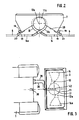
- the known spreading unit shown in Figures 1 and 2 has two fans 11, 11a, the axis 12 of which extends in the direction of travel.
- the blowers 11, 11a each have a pressure connection 13, 13a, which lead to an air distributor 14, 14a, which extends over the entire width of the scatter lines 8 on one side of the vehicle and distributes the air to the individual scatter lines.
- the stray lines 8 Immediately behind the air distributors 14, 14a, the stray lines 8 each have an injector (not shown).
- the stray lines 8 can be folded up about an axis (not shown) into a transport position and at the same time folded into shorter packages with a relatively low height.
- the storage container 2 has a floor 29 (FIG. 2) which slopes down like a roof on both sides of the longitudinal axis of the vehicle and outlet openings arranged near the side boundary of the storage container, in the area of which metering elements 18 are mounted in the form of cam wheels arranged parallel to the axis. Below the metering elements 18, metering bowls 19 are arranged under resilient contact with the metering elements, via which the metered spreading material arrives in collecting bowls 20, which are arranged on the injectors of the scatter lines 8.
- the axis of the blowers 11, 11a runs in the direction of travel.
- the necessary size of the blower therefore requires corresponding cutouts in the region of the apex of the roof-shaped floor 29, as a result of which the container volume and thus the payload are lost.
- the blowers are coupled to the PTO shaft 30 of the tractor 1 via a propshaft (not shown), which drives the blowers.
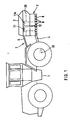
- Figure 3 shows an embodiment of the device according to the invention, in which the rotor of the blower 11 (11a) is arranged transversely to the direction of travel with a vertical axis 42, so that the blower rotor and the blower housing lie with their diametrical dimensions in a horizontal plane.
- the blower can be arranged at the lowest possible point of the spreading unit, so that the roof-shaped floor can run as flat as the angle of repose of the spreading material allows.
- the pressure ports 13, 13a are attached at approximately opposite points, to which in turn an air distributor 14, 14a connects.
- a hydraulic motor 17 sits on the blower axis 42 and is directly connected to the hydraulic vehicle electrical system of the vehicle 1 via a pressure line 38 and a return suction line 39. Instead, the hydraulic motor 42 can also be driven by a hydraulic pump mounted on the PTO shaft 30.
Landscapes
- Life Sciences & Earth Sciences (AREA)
- Environmental Sciences (AREA)
- Soil Sciences (AREA)
- Engineering & Computer Science (AREA)
- Insects & Arthropods (AREA)
- Pest Control & Pesticides (AREA)
- Wood Science & Technology (AREA)
- Zoology (AREA)
- Fertilizing (AREA)
Claims (7)
- Dispositif pour distribuer de l'engrais sur des surfaces étendues, comprenant un véhicule (1), par exemple un tracteur, avec une prise de force (30) et un attelage à trois points, et un groupe de distribution (7) accouplé audit véhicule et comportant un réservoir (2) avec un fond (29) descendant en forme de toit vers des ouvertures de sortie, des organes de dosage (18) disposés au-dessus des ouvertures de sortie ainsi qu'une pluralité de conduites de distribution (8) qui se raccordent à ces derniers avec des ouvertures d'entrée (20), s'étendent vers les deux cotés et perpendiculairement à l'axe longitudinal du véhicule, les conduites de distribution (8) à chaque côté étant par un diffuseur d'air (14,14a) et un tuyau de refoulement (13,13a) à une soufflante (11) disposée sous le fond (29) en forme de toit, lesquelles conduites de distribution se terminent, à des distances variables de l'axe longitudinal du véhicule, par des ouvertures de distribution munies d'organes distributeurs (9), caractérisé en ce que la soufflante (11) est disposée avec son axe orienté verticalement et transversalement à la direction de la marche et entraînée au moyen d'un moteur hydraulique (17) monté directement sur l'axe (12) du rotor de la soufflante (11) et en ce que la soufflante (11) comprend les tuyaux de refoulement (13,13a) et les diffuseurs d'air pour les conduites de distribution sur chaque côté relativement à l'axe longitudinal du véhicule et à l'axe tournent de la soufflante à des côtés opposés.
- Dispositif selon la revendication 1, caractérisé en ce que le moteur hydraulique (17) est couplé, par l'intermédiaire d'une conduite (31,34), avec une pompe hydraulique (15) laquelle est accouplée à son tour à la prise de force (30).
- Dispositif selon l'une des revendications 1 ou 2, caractérisé en ce que le moteur hydraulique (17) est muni d'un dispositif de recirculation.
- Dispositif selon l'une des revendications 1 à 3, caractérisé en ce qu'il comprend un dispositif de réglage pour la stabilisation de la vitesse de rotation du moteur hydraulique (17).
- Dispositif selon l'une des revendications 1 à 4, caractérisé en ce que le rotor de la soufflante (11) est réalisé en matière plastique.
- Dispositif selon l'une des revendications 1 à 5, caractérisé en ce qu'un tachymètre est prévu pour la et respectivement les soufflante(s) (11,11a) pour les conduites de distribution (8) et qu'un compte-tours est monté sur le véhicule (1).
- Dispositif selon l'une des revendications 1 à 6, caractérisé en ce qu'un indicateur de pression est monté sur le véhicule (1) et qu'un limiteur de pression est disposé en aval de la pompe hydraulique (15).
Applications Claiming Priority (4)
| Application Number | Priority Date | Filing Date | Title |
|---|---|---|---|
| DE3513739 | 1985-04-17 | ||
| DE19853513737 DE3513737A1 (de) | 1985-04-17 | 1985-04-17 | Vorrichtung zum streuen von duenger |
| DE3513737 | 1985-04-17 | ||
| DE19853513739 DE3513739A1 (de) | 1985-04-17 | 1985-04-17 | Vorrichtung zum streuen von duenger |
Publications (4)
| Publication Number | Publication Date |
|---|---|
| EP0201736A2 EP0201736A2 (fr) | 1986-11-20 |
| EP0201736A3 EP0201736A3 (en) | 1986-12-10 |
| EP0201736B1 EP0201736B1 (fr) | 1990-10-10 |
| EP0201736B2 true EP0201736B2 (fr) | 1994-01-19 |
Family
ID=25831412
Family Applications (1)
| Application Number | Title | Priority Date | Filing Date |
|---|---|---|---|
| EP86105047A Expired - Lifetime EP0201736B2 (fr) | 1985-04-17 | 1986-04-12 | Dispositif pour distribuer de l'engrais |
Country Status (2)
| Country | Link |
|---|---|
| EP (1) | EP0201736B2 (fr) |
| DE (1) | DE3674832D1 (fr) |
Families Citing this family (1)
| Publication number | Priority date | Publication date | Assignee | Title |
|---|---|---|---|---|
| DE3707739A1 (de) * | 1987-03-11 | 1988-09-22 | Amazonen Werke Dreyer H | Hydraulikanlage fuer den antrieb eines streugeraetes |
Family Cites Families (6)
| Publication number | Priority date | Publication date | Assignee | Title |
|---|---|---|---|---|
| DE2226605A1 (de) * | 1972-05-31 | 1973-12-13 | Josef Gail | Mischwerk fuer duengemittel |
| US3911650A (en) * | 1974-01-02 | 1975-10-14 | Donald F Johnson | Hay loading apparatus |
| DE2425091A1 (de) * | 1974-05-24 | 1975-11-27 | Leo L Tompkins | Druckmittelmotor |
| FR2382171A1 (fr) * | 1977-03-04 | 1978-09-29 | Nodet Gougis | Epandeur pneumatique a rampes d'epandage pivotantes |
| JPS5877905A (ja) * | 1981-09-02 | 1983-05-11 | プル−テク・リミテツド | 液圧制御弁 |
| DE3325430C2 (de) * | 1983-07-14 | 1987-03-26 | Rauch Landmaschinenfabrik GmbH, 7573 Sinzheim | Vorrichtung zum Streuen von schüttfähigem Gut |
-
1986
- 1986-04-12 DE DE8686105047T patent/DE3674832D1/de not_active Expired - Lifetime
- 1986-04-12 EP EP86105047A patent/EP0201736B2/fr not_active Expired - Lifetime
Also Published As
| Publication number | Publication date |
|---|---|
| EP0201736A3 (en) | 1986-12-10 |
| EP0201736B1 (fr) | 1990-10-10 |
| DE3674832D1 (de) | 1990-11-15 |
| EP0201736A2 (fr) | 1986-11-20 |
Similar Documents
| Publication | Publication Date | Title |
|---|---|---|
| DE69623295T2 (de) | Saat-messmethode und vorrichtung | |
| DE6930657U (de) | Vorrichtung zum verteilen oder ausstreuen pulveriger oder gekoernter stoffe | |
| DE102004030240B4 (de) | Pneumatischer Streuer zum Verteilen von Streugut, insbesondere Dünger, Saatgut oder dergleichen | |
| DE60105703T2 (de) | Fahrstuhl für Schüttgut und zugehörende Apparate | |
| EP0917819B1 (fr) | Moissonneuse-batteuse équipée d'un hache-paille | |
| DE69725773T2 (de) | Streuer mit Gewichtsmessung | |
| EP0170911B1 (fr) | Machine pour l'épandage de matériaux, en particulier d'engrais | |
| EP0201736B1 (fr) | Dispositif pour distribuer de l'engrais | |
| DE102019007686A1 (de) | Förderanordnung für Wirtschaftsdünger sowei Computerprogrammprodukt und Verfahren zum Ausbringen von Wirtschaftsdünger | |
| DE2760411C2 (fr) | ||
| DE2107575C2 (de) | Anordnung einer Aufbereitungseinrichtung an einem selbstfahrenden Schwadmäher | |
| DE3513739A1 (de) | Vorrichtung zum streuen von duenger | |
| EP2022315B1 (fr) | Ramasseuse-hacheuse automobile | |
| EP0201048B1 (fr) | Combinaison fermée d'instruments agricoles | |
| EP0175056B1 (fr) | Dispositif de transport pneumatique de flocons de fibres | |
| EP0496285B1 (fr) | Epandeur centrifuge | |
| EP0775437B1 (fr) | Dispositif agricole pour la récolte des plantes à tige | |
| CH677058A5 (en) | Hopper for granular material e.g. seeds - has attached electric blower to distribute material along pipes | |
| DE3513737A1 (de) | Vorrichtung zum streuen von duenger | |
| CH657883A5 (de) | Salzstreugeraet mit streugutbefeuchtungseinrichtung fuer ein fahrzeug. | |
| DE19814235C1 (de) | Mobile Mischanlage zur Bereitstellung von Tierfutter | |
| DE894472C (de) | Fahrbarer Stallmiststreuer | |
| EP0202462B1 (fr) | Dispositif pour distribuer de l'engrais ou un produit similaire | |
| DE3325430C2 (de) | Vorrichtung zum Streuen von schüttfähigem Gut | |
| DE102018100305A1 (de) | Anordnung zum Ausbringen von Streugut auf landwirtschaftlichen Flächen |
Legal Events
| Date | Code | Title | Description |
|---|---|---|---|
| PUAI | Public reference made under article 153(3) epc to a published international application that has entered the european phase |
Free format text: ORIGINAL CODE: 0009012 |
|
| PUAL | Search report despatched |
Free format text: ORIGINAL CODE: 0009013 |
|
| AK | Designated contracting states |
Kind code of ref document: A2 Designated state(s): DE FR GB NL SE |
|
| AK | Designated contracting states |
Kind code of ref document: A3 Designated state(s): DE FR GB NL SE |
|
| 17P | Request for examination filed |
Effective date: 19870306 |
|
| 17Q | First examination report despatched |
Effective date: 19881229 |
|
| GRAA | (expected) grant |
Free format text: ORIGINAL CODE: 0009210 |
|
| AK | Designated contracting states |
Kind code of ref document: B1 Designated state(s): DE FR GB NL SE |
|
| PG25 | Lapsed in a contracting state [announced via postgrant information from national office to epo] |
Ref country code: SE Effective date: 19901010 Ref country code: NL Effective date: 19901010 Ref country code: GB Effective date: 19901010 |
|
| REF | Corresponds to: |
Ref document number: 3674832 Country of ref document: DE Date of ref document: 19901115 |
|
| ET | Fr: translation filed | ||
| GBT | Gb: translation of ep patent filed (gb section 77(6)(a)/1977) | ||
| NLV1 | Nl: lapsed or annulled due to failure to fulfill the requirements of art. 29p and 29m of the patents act | ||
| PLBI | Opposition filed |
Free format text: ORIGINAL CODE: 0009260 |
|
| 26 | Opposition filed |
Opponent name: AMAZONEN-WERKE H. DREYER GMBH & CO.KG Effective date: 19910710 |
|
| PGFP | Annual fee paid to national office [announced via postgrant information from national office to epo] |
Ref country code: GB Payment date: 19930331 Year of fee payment: 8 |
|
| PUAH | Patent maintained in amended form |
Free format text: ORIGINAL CODE: 0009272 |
|
| STAA | Information on the status of an ep patent application or granted ep patent |
Free format text: STATUS: PATENT MAINTAINED AS AMENDED |
|
| 27A | Patent maintained in amended form |
Effective date: 19940119 |
|
| AK | Designated contracting states |
Kind code of ref document: B2 Designated state(s): DE FR GB NL SE |
|
| ET3 | Fr: translation filed ** decision concerning opposition | ||
| GBV | Gb: ep patent (uk) treated as always having been void in accordance with gb section 77(7)/1977 [no translation filed] |
Effective date: 19901010 |
|
| PGFP | Annual fee paid to national office [announced via postgrant information from national office to epo] |
Ref country code: DE Payment date: 19950427 Year of fee payment: 10 |
|
| PGFP | Annual fee paid to national office [announced via postgrant information from national office to epo] |
Ref country code: FR Payment date: 19950428 Year of fee payment: 10 |
|
| PG25 | Lapsed in a contracting state [announced via postgrant information from national office to epo] |
Ref country code: FR Effective date: 19961227 |
|
| PG25 | Lapsed in a contracting state [announced via postgrant information from national office to epo] |
Ref country code: DE Effective date: 19970101 |
|
| REG | Reference to a national code |
Ref country code: FR Ref legal event code: ST |