EP0201756A2 - Pointeau de centrage - Google Patents
Pointeau de centrage Download PDFInfo
- Publication number
- EP0201756A2 EP0201756A2 EP86105394A EP86105394A EP0201756A2 EP 0201756 A2 EP0201756 A2 EP 0201756A2 EP 86105394 A EP86105394 A EP 86105394A EP 86105394 A EP86105394 A EP 86105394A EP 0201756 A2 EP0201756 A2 EP 0201756A2
- Authority
- EP
- European Patent Office
- Prior art keywords
- pressure plate
- driver according
- face driver
- bolts
- elastically deformable
- Prior art date
- Legal status (The legal status is an assumption and is not a legal conclusion. Google has not performed a legal analysis and makes no representation as to the accuracy of the status listed.)
- Withdrawn
Links
- 238000010276 construction Methods 0.000 abstract description 3
- 230000001771 impaired effect Effects 0.000 description 2
- 230000004323 axial length Effects 0.000 description 1
- 230000007547 defect Effects 0.000 description 1
- 238000003754 machining Methods 0.000 description 1
- 230000036316 preload Effects 0.000 description 1
Images



Classifications
-
- B—PERFORMING OPERATIONS; TRANSPORTING
- B23—MACHINE TOOLS; METAL-WORKING NOT OTHERWISE PROVIDED FOR
- B23B—TURNING; BORING
- B23B33/00—Drivers; Driving centres, Nose clutches, e.g. lathe dogs
- B23B33/005—Drivers with driving pins or the like
-
- Y—GENERAL TAGGING OF NEW TECHNOLOGICAL DEVELOPMENTS; GENERAL TAGGING OF CROSS-SECTIONAL TECHNOLOGIES SPANNING OVER SEVERAL SECTIONS OF THE IPC; TECHNICAL SUBJECTS COVERED BY FORMER USPC CROSS-REFERENCE ART COLLECTIONS [XRACs] AND DIGESTS
- Y10—TECHNICAL SUBJECTS COVERED BY FORMER USPC
- Y10T—TECHNICAL SUBJECTS COVERED BY FORMER US CLASSIFICATION
- Y10T279/00—Chucks or sockets
- Y10T279/25—Compensation for eccentricity
-
- Y—GENERAL TAGGING OF NEW TECHNOLOGICAL DEVELOPMENTS; GENERAL TAGGING OF CROSS-SECTIONAL TECHNOLOGIES SPANNING OVER SEVERAL SECTIONS OF THE IPC; TECHNICAL SUBJECTS COVERED BY FORMER USPC CROSS-REFERENCE ART COLLECTIONS [XRACs] AND DIGESTS
- Y10—TECHNICAL SUBJECTS COVERED BY FORMER USPC
- Y10T—TECHNICAL SUBJECTS COVERED BY FORMER US CLASSIFICATION
- Y10T82/00—Turning
- Y10T82/26—Work driver
Definitions
- the invention relates to a face driver for centering and driving workpieces clamped on a lathe, which consists of a carrier connected to the latter, a center point supported on it and a plurality of driver bolts arranged uniformly distributed over the circumference, which are slidably inserted in the carrier and by means of a can be pressed centrally against the workpiece to be clamped by a pressure member.
- a face driver of this type is known from DE-OS 34 00 082.
- the pressure plate is designed as a rigid component and clamped between a piston rod of an actuating piston arranged in a hydraulic cylinder and the driving pin. Since the end of the piston rod which bears against the pressure plate is convexly curved and each restoring pin is assigned a restoring spring which is supported on the pressure plate and the carrier, the pressure plate, provided that the carrier has only two or three driver bolts is fitted, tilt so that the flat surface errors of the workpiece, although this is not the task of this known face driver, have to be compensated for to a limited extent.
- the object of the invention is therefore to improve the face driver of the aforementioned type in such a way that, regardless of the number of driver bolts inserted in the carrier, an automatic compensation of flat surface tolerances of the workpiece to be clamped is to be carried out.
- the construction effort required for this should be kept low, but it should nevertheless be ensured that the clamping force introduced via the pressure member can be transferred to the workpiece without a decrease in clamping force and that reliable clamping can always be carried out.
- this is achieved in that the pressure plate is kept swinging in the axial direction of the carrier and in that the parts of the pressure plate assigned to the driving pins are designed to be elastically deformable.
- the pressure plate can also additionally or separately be connected centrally via a ball joint to the pressure member, where the ball joint should consist of a ball head molded onto the pressure member and a dome-shaped recess incorporated into the pressure plate, in which the ball head is held.
- the elastically deformable parts of the Drsok plate can be formed in a simple embodiment by arms projecting radially outward from the hub, but it is also possible to form these parts as resilient segments in the axial direction, in which slots directed radially into the pressure plate between the contact surfaces of the driving pins or savings are included.
- the elastically deformable parts of the pressure plate can also be formed by an insert made of hyaroplastic material inserted therein, the insert in the areas assigned to the individual driving bolts in the end face machined recesses in the pressure plate or in a side of the pressure plate facing the driving bolt incorporated circumferential recess is to be used, which are sealed by means of a cover plate and balls or bolts held in this as intermediate members.
- the driver pins can also be supported on the elastically deformable parts of the pressure plate via an intermediate member.
- the intermediate links should each be designed as a ball or as a bolt provided with ball heads formed on the ends.
- the pressure plate with elastically deformable parts arranged axially one behind the other in two planes, which are arranged offset with respect to one another, and to equip the driving pins with an elastically deformable intermediate piece inserted therein.
- driver bolts which are inserted into the carrier at different diameters, it is appropriate to support them on the common thrust washer by means of a compensating element and an intermediate element designed as a ball.
- the face driver designed according to the invention makes it possible, in a simple manner, to automatically also allow larger flat surface tolerances of a workpiece, which are inevitably, for. B. result in sawing to compensate, regardless of the number of driving bolts used in a carrier. If the pressure plate is held in an oscillating manner and its parts assigned to the driving pins are designed to be elastically deformable, each driving pin can thus perform a compensating movement if necessary. Even workpieces with uneven or inclined end faces can therefore be reliably clamped with the end driver designed according to the proposal without having to be machined beforehand.
- the face driver shown in FIG. 1 and designated 11 serves for centering and non-rotatably clamping between tips of a workpiece 4 on a lathe 1 and consists of a support 12 fastened to it by means of screws 17, a bore 13 inserted in a central conical bore 13 and attached the center point 14 supported on the carrier 12 as well as a plurality of driver bolts 16 arranged axially displaceably in bores 15 and distributed uniformly over the circumference and a pressure plate 21 arranged in a recess 18 of the carrier 12.
- the provided with centering holes 5 and 6 workpiece 4 is rotatably held on a tip 2 used in a bearing housing 3 as a counter bearing and is rotated by the face driver 11 so that machining of the workpiece 4 over its entire axial length is possible in one operation is.
- the pressure plate 21 is kept swinging in the axial direction A of the lathe 1.
- the end of the pressure member 19 is designed as a spherical head 20 and a dome-shaped recess 23 which accommodates it is machined into the pressure plate 21, so that a ball joint is formed.
- the outer lateral surface 22 of the pressure plate 21 is convexly curved and lies against the cylindrical inner surface of the recess 18, the pressure plate 21 can thus oscillate around the center of the ball head 20.
- the pressure plate 21 is elastically deformable in the parts assigned to the driving pins 16 educated.
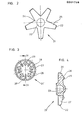
- arms 25 projecting radially outwards are formed on a hub 24, against which the driving pins 16 bear with a convex curved surface 35 worked on them.
- the driving pin 16 can thus perform axial movements independently of one another, so that in this way, since the arms 25 of the pressure plate 21 can move back more or less, plane surface errors of the workpiece 4 can be compensated for automatically without the clamping thereof being impaired.
- the pressure plate 21 is guided centrally and in its outer area, so tilting is excluded. Also, when the arms 25 are pivoted, the contact of the driving pins 16 with them is not impaired, since these are equipped with a convexly curved contact surface 35, but rather pivot movements are also compensated for.
- the individual driving bolts 16 become independent of one another, since the arms 25 of the pressure plate 21 are elastically deformable and can thus deflect, correspondingly pushed back, plane surface defects of the workpiece 4 are thereby avoided without the End face 7 must be processed, balanced.
- elastically deformable segments 26 are provided, which cooperate with the driving pins 16.
- the segments 26 resilient in the axial direction A are created here by radially directed slots 27, which are worked into the pressure plate 21 'between the contact surfaces 29 of the driving pins 16.
- convexly curved cams 28 are formed on the pressure plate 21 ', thus forming curved contact surfaces 29.
- 16 recesses 31 are machined into the pressure plate 21 "in accordance with the arrangement of the driving pins, which are filled with an insert 30 made of hydroplastic material as elastically deformable parts of the pressure plate 21".
- the recesses 31 are closed by means of a cover plate 32 and a ball 33 held in this as intermediate members.
- bolts 34 are provided as intermediate members, which have ball heads 36 and 37 on the pressure plate 21 'or segments provided with segments 2S. rest against the pressure plate 21 ′′ equipped with an insert 30 ′ made of hydroplastic material and the driving pins 16 ′.
- the insert 30 ' is here made in a circumferential recess 31' which is closed by an annular plate 32 'and the bolts 34,
- the face driver 11 ' is equipped with a pressure plate 21 "which is provided with elastically deformable segments 26' and 26" which are axially arranged one behind the other in two planes and which are offset with respect to one another.
- the segments 26 ', 26 can be made large, or a plurality of driver bolts 16, 16" can be provided.
- an intermediate piece 38 is inserted in each of the driving bolts 16 ′′ as an energy store in order to be able to maintain the contact pressure in the event of a possible drop in the clamping force.
- the driver bolts 16 ′′ are arranged on different diameters, so that different center points 14 and 14 ′ can be used and workpieces of different diameters can also be clamped
- Driving pins 16 ′′ ′′ against a workpiece to be clamped by a common pressure plate 21 ′′ are inserted into bores 40 of the carrier 12 compensating elements 39, on which the balls 33 held in the cover plate 32 act.
- an insert 30 or 30 "made of hydroplastic material is provided as elastically deformable parts of the pressure plate 21", which is inserted in the differently shaped recesses 31 or 31 ".
Landscapes
- Engineering & Computer Science (AREA)
- Mechanical Engineering (AREA)
- Jigs For Machine Tools (AREA)
- Gripping On Spindles (AREA)
Applications Claiming Priority (2)
| Application Number | Priority Date | Filing Date | Title |
|---|---|---|---|
| DE19853517633 DE3517633A1 (de) | 1985-05-15 | 1985-05-15 | Stirnmitnehmer |
| DE3517633 | 1985-05-15 |
Publications (2)
| Publication Number | Publication Date |
|---|---|
| EP0201756A2 true EP0201756A2 (fr) | 1986-11-20 |
| EP0201756A3 EP0201756A3 (fr) | 1988-07-27 |
Family
ID=6270879
Family Applications (1)
| Application Number | Title | Priority Date | Filing Date |
|---|---|---|---|
| EP86105394A Withdrawn EP0201756A3 (fr) | 1985-05-15 | 1986-04-18 | Pointeau de centrage |
Country Status (5)
| Country | Link |
|---|---|
| US (1) | US4677885A (fr) |
| EP (1) | EP0201756A3 (fr) |
| JP (1) | JPS61260904A (fr) |
| DE (1) | DE3517633A1 (fr) |
| ES (1) | ES8704775A1 (fr) |
Cited By (3)
| Publication number | Priority date | Publication date | Assignee | Title |
|---|---|---|---|---|
| EP1759794A3 (fr) * | 2005-09-01 | 2009-06-17 | Zwiesel Kristallglas AG | Mandrin avec équilibrage des forces |
| EP2444183A1 (fr) * | 2010-10-22 | 2012-04-25 | Röhm GmbH | Douille d'accouplement avant |
| CN107249795A (zh) * | 2015-02-18 | 2017-10-13 | 格里森工场 | 补偿装置及装配有这种类型的补偿装置的工件的夹持装置 |
Families Citing this family (17)
| Publication number | Priority date | Publication date | Assignee | Title |
|---|---|---|---|---|
| US4989887A (en) * | 1990-06-15 | 1991-02-05 | Jacobs Chuck Technology Corporation | Methods and apparatus for adjusting the center of a collet |
| US5243885A (en) * | 1991-05-16 | 1993-09-14 | Dana Corporation | Face driving center assembly for lathe |
| DE4123859C2 (de) * | 1991-07-18 | 1994-05-05 | Heller Geb Gmbh Maschf | Verfahren zur spanenden Bearbeitung von Werkstücken mit rotationssymmetrischen Flächen, vorzugsweise von Kurbelwellen, und Vorrichtung zur Durchführung eines solchen Verfahrens |
| US5193825A (en) * | 1991-10-03 | 1993-03-16 | Jacobs Chuck Technology Corporation | Apparatus for adjusting the center of a collet |
| KR950008007A (ko) * | 1993-09-07 | 1995-04-15 | 수우 에이 그리핀 | 공작물을 기계가공하도록 회전시키는 장치 및 기계 가공에 의한 제품 형성 방법 |
| US5752706A (en) * | 1996-07-18 | 1998-05-19 | Hodges; Lyndon W. | Adjustable tool holder for machine tools |
| US6374713B1 (en) | 2000-04-10 | 2002-04-23 | Kevin J. Bissett | Facedriver with fully-adaptable workpiece engagement and enhanced centerpoint force |
| DE50009428D1 (de) * | 2000-09-21 | 2005-03-10 | Illinois Tool Works | Verfahren zur Bearbeitung eines Werkstückes und Futter mit Zentrierdorn zu seiner Durchführung |
| DE10059116A1 (de) * | 2000-11-28 | 2002-06-06 | Reishauer Ag | Vorrichtung zur stirnseitigen Mitnahme verzahnter Werkstücke |
| WO2007098489A2 (fr) * | 2006-02-22 | 2007-08-30 | Kneebusch William C | Procédé et appareil d'alimentation en barres d'un tour à découper |
| JP4756174B2 (ja) * | 2006-03-15 | 2011-08-24 | コマツNtc株式会社 | ワーク加工方法 |
| CN100566901C (zh) * | 2007-01-29 | 2009-12-09 | 陶波 | 制齿机床送料机构 |
| US9446453B2 (en) | 2013-07-03 | 2016-09-20 | Big Tree Tools, Llc | Drive center with guard |
| CN104551266A (zh) * | 2014-12-31 | 2015-04-29 | 陈仁杰 | 磨齿机工件定位旋转装置 |
| RU2693667C1 (ru) * | 2019-02-15 | 2019-07-03 | Федеральное государственное бюджетное образовательное учреждение высшего образования "Тверской государственный технический университет" | Патрон кулачковый механизированный |
| RU2714361C1 (ru) * | 2019-02-15 | 2020-02-14 | Федеральное государственное бюджетное образовательное учреждение высшего образования "Тверской государственный технический университет" | Способ установки заготовки на центрах токарного станка |
| WO2025100627A1 (fr) * | 2023-11-08 | 2025-05-15 | (주)포인트텍 | Dispositif d'entraînement frontal d'une machine-outil |
Family Cites Families (6)
| Publication number | Priority date | Publication date | Assignee | Title |
|---|---|---|---|---|
| BE521923A (fr) * | 1953-04-04 | |||
| DE1204498B (de) * | 1962-09-14 | 1965-11-04 | Kosta Maschinenwerkzeuge Spann | Mitnehmerspitze fuer Werkzeugmaschinen |
| DE1902314U (de) * | 1964-07-25 | 1964-10-15 | Monforts Fa A | Mitnehmerkoerner fuer drehbaenke. |
| DE2741777A1 (de) * | 1977-09-16 | 1979-03-29 | Schmid Kosta Kg | Stirnseitenmitnehmer |
| US4604923A (en) * | 1983-01-18 | 1986-08-12 | Index-Werke Komm. Ges. Hahn & Tessky | Method of machining a workpiece between centers and a clamping device for performing this method |
| DE3400082A1 (de) * | 1983-01-18 | 1984-07-19 | Index-Werke Kg Hahn & Tessky, 7300 Esslingen | Verfahren zur bearbeitung eines werkstuecks in einer drehmaschine zwischen spitzen sowie spannvorrichtung zur durchfuehrung dieses verfahrens |
-
1985
- 1985-05-15 DE DE19853517633 patent/DE3517633A1/de not_active Withdrawn
-
1986
- 1986-04-18 EP EP86105394A patent/EP0201756A3/fr not_active Withdrawn
- 1986-05-14 JP JP61108758A patent/JPS61260904A/ja active Pending
- 1986-05-14 ES ES554952A patent/ES8704775A1/es not_active Expired
- 1986-05-15 US US06/863,611 patent/US4677885A/en not_active Expired - Fee Related
Cited By (4)
| Publication number | Priority date | Publication date | Assignee | Title |
|---|---|---|---|---|
| EP1759794A3 (fr) * | 2005-09-01 | 2009-06-17 | Zwiesel Kristallglas AG | Mandrin avec équilibrage des forces |
| EP2444183A1 (fr) * | 2010-10-22 | 2012-04-25 | Röhm GmbH | Douille d'accouplement avant |
| CN107249795A (zh) * | 2015-02-18 | 2017-10-13 | 格里森工场 | 补偿装置及装配有这种类型的补偿装置的工件的夹持装置 |
| CN107249795B (zh) * | 2015-02-18 | 2019-08-06 | 格里森工场 | 补偿装置及装配有这种类型的补偿装置的工件的夹持装置 |
Also Published As
| Publication number | Publication date |
|---|---|
| EP0201756A3 (fr) | 1988-07-27 |
| ES8704775A1 (es) | 1987-04-16 |
| ES554952A0 (es) | 1987-04-16 |
| US4677885A (en) | 1987-07-07 |
| JPS61260904A (ja) | 1986-11-19 |
| DE3517633A1 (de) | 1986-11-20 |
Similar Documents
| Publication | Publication Date | Title |
|---|---|---|
| EP0201756A2 (fr) | Pointeau de centrage | |
| DE4022579A1 (de) | Werkzeug fuer den einsatz in werkzeugmaschinen | |
| DE3879756T2 (de) | Spannfutter, insbesondere fuer werkzeugmaschine. | |
| EP3456448B1 (fr) | Dispositif d'accouplement | |
| DE102015005951A1 (de) | Werkstückspannvorrichtung mit Stirnseitenmitnehmer | |
| WO2003013769A2 (fr) | Outil rotatif a plusieurs tranchants | |
| DE4104474C1 (fr) | ||
| DE3914552A1 (de) | Waelzlagerung | |
| EP0307550A1 (fr) | Support d'outil interchangeable et pivotant pour robot | |
| DE1752621A1 (de) | Huelsenspannfutter | |
| EP1837108B1 (fr) | Mandrin à diaphragme | |
| DE4441820B4 (de) | Bohr- und/oder Schlaghammer | |
| EP1757392B1 (fr) | Mandrin à diaphragme | |
| EP3292932B1 (fr) | Ensemble à ressort permettant de générer la force de serrage d'un dispositif de serrage et dispositif de serrage pourvu d'un tel ensemble à ressort | |
| EP1101554A1 (fr) | Mandrin pour machines-outils | |
| DE2753284C2 (de) | Schmitzringanordnung zwischen zwei Druckwerkszylindern | |
| DE1075921B (de) | Bohrstange | |
| DE202017100117U1 (de) | Sonderausstattung zur Änderung einer CNC-Drehmaschine in ein horizontales Bearbeitungszentrum | |
| DE2715234A1 (de) | Selbstabhebender werkzeugspanner | |
| DE3730516A1 (de) | Auswechselbare werkzeugaufnahme | |
| DD284631A5 (de) | Mitnehmerelemente zur uebertragung eines drehmomentes von einem werkzeughalter auf einen werkzeugkopf | |
| EP0017967A1 (fr) | Outil d'alésage comportant un outil de tournage | |
| DE2557248A1 (de) | Vorrichtung zum indexieren von maschinenteilen zueinander | |
| DE1605099C (de) | Drehzapfenlagerung für Schienenfahrzeuge | |
| DE2840184A1 (de) | Stirnmitnehmer zum zentrieren und mitnehmen von werkstuecken fuer die arbeitsspindel einer drehmaschine |
Legal Events
| Date | Code | Title | Description |
|---|---|---|---|
| PUAI | Public reference made under article 153(3) epc to a published international application that has entered the european phase |
Free format text: ORIGINAL CODE: 0009012 |
|
| AK | Designated contracting states |
Kind code of ref document: A2 Designated state(s): CH DE FR GB IT LI SE |
|
| PUAL | Search report despatched |
Free format text: ORIGINAL CODE: 0009013 |
|
| AK | Designated contracting states |
Kind code of ref document: A3 Designated state(s): CH DE FR GB IT LI SE |
|
| STAA | Information on the status of an ep patent application or granted ep patent |
Free format text: STATUS: THE APPLICATION IS DEEMED TO BE WITHDRAWN |
|
| 18D | Application deemed to be withdrawn |
Effective date: 19890128 |
|
| RIN1 | Information on inventor provided before grant (corrected) |
Inventor name: SCHMID, HERBERT, ING. GRAD. Inventor name: HIESTAND, KARL |