EP0201769B1 - Dévidoir pour tuyaux d'aspiration - Google Patents
Dévidoir pour tuyaux d'aspiration Download PDFInfo
- Publication number
- EP0201769B1 EP0201769B1 EP86105560A EP86105560A EP0201769B1 EP 0201769 B1 EP0201769 B1 EP 0201769B1 EP 86105560 A EP86105560 A EP 86105560A EP 86105560 A EP86105560 A EP 86105560A EP 0201769 B1 EP0201769 B1 EP 0201769B1
- Authority
- EP
- European Patent Office
- Prior art keywords
- hose
- reel
- reel body
- suction
- extraction
- Prior art date
- Legal status (The legal status is an assumption and is not a legal conclusion. Google has not performed a legal analysis and makes no representation as to the accuracy of the status listed.)
- Expired - Lifetime
Links
- 230000000284 resting effect Effects 0.000 abstract 1
- 238000005096 rolling process Methods 0.000 abstract 1
- 239000007789 gas Substances 0.000 description 2
- 238000004519 manufacturing process Methods 0.000 description 2
- 238000004804 winding Methods 0.000 description 2
- 230000006978 adaptation Effects 0.000 description 1
- 238000005452 bending Methods 0.000 description 1
- 231100000206 health hazard Toxicity 0.000 description 1
- XLYOFNOQVPJJNP-UHFFFAOYSA-N water Substances O XLYOFNOQVPJJNP-UHFFFAOYSA-N 0.000 description 1
Images


Classifications
-
- B—PERFORMING OPERATIONS; TRANSPORTING
- B08—CLEANING
- B08B—CLEANING IN GENERAL; PREVENTION OF FOULING IN GENERAL
- B08B15/00—Preventing escape of dirt or fumes from the area where they are produced; Collecting or removing dirt or fumes from that area
- B08B15/002—Preventing escape of dirt or fumes from the area where they are produced; Collecting or removing dirt or fumes from that area using a central suction system, e.g. for collecting exhaust gases in workshops
-
- B—PERFORMING OPERATIONS; TRANSPORTING
- B65—CONVEYING; PACKING; STORING; HANDLING THIN OR FILAMENTARY MATERIAL
- B65H—HANDLING THIN OR FILAMENTARY MATERIAL, e.g. SHEETS, WEBS, CABLES
- B65H75/00—Storing webs, tapes, or filamentary material, e.g. on reels
- B65H75/02—Cores, formers, supports, or holders for coiled, wound, or folded material, e.g. reels, spindles, bobbins, cop tubes, cans, mandrels or chucks
- B65H75/18—Constructional details
- B65H75/20—Skeleton construction, e.g. formed of wire
-
- B—PERFORMING OPERATIONS; TRANSPORTING
- B65—CONVEYING; PACKING; STORING; HANDLING THIN OR FILAMENTARY MATERIAL
- B65H—HANDLING THIN OR FILAMENTARY MATERIAL, e.g. SHEETS, WEBS, CABLES
- B65H75/00—Storing webs, tapes, or filamentary material, e.g. on reels
- B65H75/02—Cores, formers, supports, or holders for coiled, wound, or folded material, e.g. reels, spindles, bobbins, cop tubes, cans, mandrels or chucks
- B65H75/34—Cores, formers, supports, or holders for coiled, wound, or folded material, e.g. reels, spindles, bobbins, cop tubes, cans, mandrels or chucks specially adapted or mounted for storing and repeatedly paying-out and re-storing lengths of material provided for particular purposes, e.g. anchored hoses, power cables
- B65H75/38—Cores, formers, supports, or holders for coiled, wound, or folded material, e.g. reels, spindles, bobbins, cop tubes, cans, mandrels or chucks specially adapted or mounted for storing and repeatedly paying-out and re-storing lengths of material provided for particular purposes, e.g. anchored hoses, power cables involving the use of a core or former internal to, and supporting, a stored package of material
-
- B—PERFORMING OPERATIONS; TRANSPORTING
- B65—CONVEYING; PACKING; STORING; HANDLING THIN OR FILAMENTARY MATERIAL
- B65H—HANDLING THIN OR FILAMENTARY MATERIAL, e.g. SHEETS, WEBS, CABLES
- B65H2701/00—Handled material; Storage means
- B65H2701/30—Handled filamentary material
- B65H2701/33—Hollow or hose-like material
Definitions
- the invention relates to a hose drum for suction hoses.
- suction hoses When repairing and servicing motor vehicles, the exhaust gases that occur must be extracted using suction hoses. So that these suction hoses do not interfere when not in use, it is known from FR-A-2 180 983 to roll them up on hose reels mounted above the work station. These known hose drums have a smooth cylindrical drum shell, but it is not guaranteed that the suction hose will be rolled up close together. Much more gaps can form between the hose turns or the hose ruptures and is thereby crushed and damaged. This creates cracks in the hose through which the exhaust gases can escape and thus pose a health hazard to the workplace.
- hose drums for water or compressed air hoses are known, which are designed as a closed shell, which have helically extending grooves on their surface.
- Such known hose drums must be made relatively heavy and stable so that they are not deformed or damaged by the rigid hoses to be wound up.
- the object of the present invention is therefore to create a hose reel of the type mentioned at the outset, which can be produced in a simple and economical manner and in which a relatively soft suction hose with a large diameter can be rolled up without deformation.
- the structure of wires allows economical production and perfect adaptation to the desired outer shape, resulting in a particularly stable structure.
- a helically wound guide basket is used, through which the hose is guided in a continuous curve from an opening of the drum shell to the suction line in the axis of the drum body.
- a hose drum 2 is rotatably mounted on a frame 1.
- the lateral surface 3 has part-circular grooves 4 which run around the lateral surface 3 in a helical manner and to which the windings of the suction hose 5 closely abut.
- a plug-in motor 7 arranged in its axis, the axis 8 of which is firmly connected to the frame 1 and the circumferential jacket of which drives the drum body via pins 9.
- a sleeve 10 is rotatably mounted in the frame 1, to which a suction line 11 is connected. This leads to a suction device, not shown.
- the sleeve 10 is connected to one end of the suction hose 5, which is guided into the interior of the drum body via an opening 12 in the lateral surface 3.
- a helically wound guide basket 13 is provided which leads inwards from the lateral surface 3 and which allows the suction hose to be continuously introduced to the sleeve 10.
- the drum body 6 is formed from wires which can be bent into the desired shape in a particularly economical manner and ensure a stable structure of the drum body.
- the drum body 6 consists of an outer basket 14 and the associated axle sleeves 15 and 16.
- Outer basket 14 consists of axially extending wires 17, which are bent from a straight wire in the middle into the part-circular grooves. Their ends are bent by 90 ° and later form the end faces 18 of the drum body 6. The helical course of the grooves over the outer surface 3 can be easily achieved by bending the wires at changing distances from their ends.
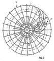
- the two axle sleeves 15 and 16 are also formed from axially extending wires 19 and 20, the ends of which are bent at right angles and extend in the end faces 18 between the ends of the wires 17 from the outer basket 14. (See Fig. 3) Both the wire ends 17 and 19 are welded together in the end face 18 by wire rings 21.
- the outer surface 3 is also helically wrapped by a wire 22, so that the drum body 6 is extremely stable.
Landscapes
- Storing, Repeated Paying-Out, And Re-Storing Of Elongated Articles (AREA)
- Rigid Pipes And Flexible Pipes (AREA)
- Storage Of Web-Like Or Filamentary Materials (AREA)
- External Artificial Organs (AREA)
Claims (5)
Priority Applications (1)
| Application Number | Priority Date | Filing Date | Title |
|---|---|---|---|
| AT86105560T ATE60565T1 (de) | 1985-05-11 | 1986-04-22 | Schlauchtrommel fuer absaugschlaeuche. |
Applications Claiming Priority (2)
| Application Number | Priority Date | Filing Date | Title |
|---|---|---|---|
| DE19853517150 DE3517150A1 (de) | 1985-05-11 | 1985-05-11 | Schlauchtrommel fuer absaugschlaeuche |
| DE3517150 | 1985-05-11 |
Publications (3)
| Publication Number | Publication Date |
|---|---|
| EP0201769A2 EP0201769A2 (fr) | 1986-11-20 |
| EP0201769A3 EP0201769A3 (en) | 1987-12-09 |
| EP0201769B1 true EP0201769B1 (fr) | 1991-01-30 |
Family
ID=6270588
Family Applications (1)
| Application Number | Title | Priority Date | Filing Date |
|---|---|---|---|
| EP86105560A Expired - Lifetime EP0201769B1 (fr) | 1985-05-11 | 1986-04-22 | Dévidoir pour tuyaux d'aspiration |
Country Status (4)
| Country | Link |
|---|---|
| EP (1) | EP0201769B1 (fr) |
| JP (1) | JPS6256273A (fr) |
| AT (1) | ATE60565T1 (fr) |
| DE (2) | DE3517150A1 (fr) |
Families Citing this family (2)
| Publication number | Priority date | Publication date | Assignee | Title |
|---|---|---|---|---|
| DE59106552D1 (de) * | 1991-08-27 | 1995-10-26 | Carsten Bardehle | Saugschlauchtrommel. |
| CN110014011B (zh) * | 2019-04-20 | 2020-07-24 | 杭州富阳和翔模具有限公司 | 一种用于收集粉尘的可自动分类的多功能设备 |
Family Cites Families (7)
| Publication number | Priority date | Publication date | Assignee | Title |
|---|---|---|---|---|
| DE492617C (de) * | 1928-11-01 | 1930-02-26 | Gustav Menzel | Schlauchhaspel mit selbsttaetiger Aufwickelvorrichtung |
| US2478540A (en) * | 1948-05-17 | 1949-08-09 | Universal Properties Inc | Take-up hose reeling equipment |
| US3011201A (en) * | 1959-03-31 | 1961-12-05 | Cymara Hermann Karl | Vacuum dust pan and reel |
| GB1138393A (en) * | 1966-02-01 | 1969-01-01 | Gkn Group Services Ltd | Improvements relating to reels, drums, and the like for holding or containing an article or articles |
| GB1104000A (en) * | 1966-02-24 | 1968-02-21 | Andrew George Philip Haselden | Improvements in or relating to hose reels |
| SE353242B (fr) * | 1972-04-18 | 1973-01-29 | B Nederman | |
| DE2823024A1 (de) * | 1978-05-26 | 1979-11-29 | Grimm Willi J | Wasserschlauchtrommel |
-
1985
- 1985-05-11 DE DE19853517150 patent/DE3517150A1/de not_active Withdrawn
-
1986
- 1986-04-22 AT AT86105560T patent/ATE60565T1/de not_active IP Right Cessation
- 1986-04-22 EP EP86105560A patent/EP0201769B1/fr not_active Expired - Lifetime
- 1986-04-22 DE DE8686105560T patent/DE3677252D1/de not_active Expired - Lifetime
- 1986-05-09 JP JP61104716A patent/JPS6256273A/ja active Pending
Also Published As
| Publication number | Publication date |
|---|---|
| DE3677252D1 (de) | 1991-03-07 |
| EP0201769A3 (en) | 1987-12-09 |
| DE3517150A1 (de) | 1986-11-13 |
| EP0201769A2 (fr) | 1986-11-20 |
| ATE60565T1 (de) | 1991-02-15 |
| JPS6256273A (ja) | 1987-03-11 |
Similar Documents
| Publication | Publication Date | Title |
|---|---|---|
| DE68908266T2 (de) | Auf- und Abwickelvorrichtung für faseroptische Kabel. | |
| DE2357047C2 (de) | Verfahren zum Kürzen einer Bewehrung vor dem Befestigen einer flexiblen Leitung an einem steifen Kupplungsstück | |
| DE2255851B2 (de) | Elastisch aufgehängter Hohlleiter | |
| DE2848366C2 (de) | Verfahren zum Herstellen eines Spleißes zum Verbinden zweier Seillängen | |
| DE2758463B2 (de) | Endoskop mit flexiblem Endabschnitt und Krümmungseinrichtung dafür | |
| DE1775881C3 (de) | Verfahren zum Herstellen einer Drahtwendel für einen flexiblen Schlauch | |
| DE1685829A1 (de) | Drahtstrang sowie ein Verfahren und eine Vorrichtung zu seiner Herstellung | |
| DE1125025B (de) | Verfahren zur Herstellung einer dehnbaren elektrischen Leitungsschnur | |
| DE634552C (de) | Radiale Leitungszufuehrung zu einem gegenueber einem festen Traggestell drehbaren und starken Verdrehungen ausgesetzten Drehgestell | |
| DE2062418B2 (de) | Saugschlauch und verfahren zu seiner herstellung | |
| DE2219816A1 (fr) | ||
| DE3722520C2 (fr) | ||
| EP0201769B1 (fr) | Dévidoir pour tuyaux d'aspiration | |
| DE487800C (de) | Kabeltrommel | |
| DE2913519B2 (de) | Flexible Rohrleitung | |
| DE2042183C3 (fr) | ||
| DE3410637C2 (fr) | ||
| DE2805585C2 (de) | Schutzschlauch für Lichtleitkabel | |
| DE2042183B2 (de) | Biegsamer schlauch | |
| EP2535303A1 (fr) | Dispositif pour dérouler et enrouler un ou plusieurs câbles | |
| DE3100698C2 (de) | Aufrolleinrichtung für einen flexiblen Schlauch oder dergleichen | |
| DE2519208C3 (de) | Elektrische Drosselspule mit einem ringförmigen Blechkern aus radial geschichteten Blechen | |
| DE2505741C3 (de) | Wulstkern für Fahrzeugluftreifen | |
| DE885738C (de) | Elektrisches Rohrkabel zur UEbertragung magnetischer Wellen | |
| DE2501935C2 (de) | Dauer- oder wasserwellwickel |
Legal Events
| Date | Code | Title | Description |
|---|---|---|---|
| PUAI | Public reference made under article 153(3) epc to a published international application that has entered the european phase |
Free format text: ORIGINAL CODE: 0009012 |
|
| AK | Designated contracting states |
Kind code of ref document: A2 Designated state(s): AT CH DE FR GB IT LI NL SE |
|
| PUAL | Search report despatched |
Free format text: ORIGINAL CODE: 0009013 |
|
| AK | Designated contracting states |
Kind code of ref document: A3 Designated state(s): AT CH DE FR GB IT LI NL SE |
|
| 17P | Request for examination filed |
Effective date: 19880415 |
|
| 17Q | First examination report despatched |
Effective date: 19891107 |
|
| RAP3 | Party data changed (applicant data changed or rights of an application transferred) |
Owner name: CHRISTIAN O. GRUHL GMBH & CO. |
|
| RIN1 | Information on inventor provided before grant (corrected) |
Inventor name: GRUHL, CHRISTIAN O. |
|
| GRAA | (expected) grant |
Free format text: ORIGINAL CODE: 0009210 |
|
| AK | Designated contracting states |
Kind code of ref document: B1 Designated state(s): AT CH DE FR GB IT LI NL SE |
|
| PG25 | Lapsed in a contracting state [announced via postgrant information from national office to epo] |
Ref country code: NL Effective date: 19910130 Ref country code: IT Free format text: LAPSE BECAUSE OF FAILURE TO SUBMIT A TRANSLATION OF THE DESCRIPTION OR TO PAY THE FEE WITHIN THE PRE;WARNING: LAPSES OF ITALIAN PATENTS WITH EFFECTIVE DATE BEFORE 2007 MAY HAVE OCCURRED AT ANY TIME BEFORE 2007. THE CORRECT EFFECTIVE DATE MAY BE DIFFERENT FROM THE ONE RECORDED.SCRIBED TIME-LIMIT Effective date: 19910130 Ref country code: FR Effective date: 19910130 Ref country code: SE Effective date: 19910130 Ref country code: GB Effective date: 19910130 |
|
| REF | Corresponds to: |
Ref document number: 60565 Country of ref document: AT Date of ref document: 19910215 Kind code of ref document: T |
|
| REF | Corresponds to: |
Ref document number: 3677252 Country of ref document: DE Date of ref document: 19910307 |
|
| PG25 | Lapsed in a contracting state [announced via postgrant information from national office to epo] |
Ref country code: AT Effective date: 19910422 |
|
| PG25 | Lapsed in a contracting state [announced via postgrant information from national office to epo] |
Ref country code: LI Effective date: 19910430 Ref country code: CH Effective date: 19910430 |
|
| EN | Fr: translation not filed | ||
| NLV1 | Nl: lapsed or annulled due to failure to fulfill the requirements of art. 29p and 29m of the patents act | ||
| GBV | Gb: ep patent (uk) treated as always having been void in accordance with gb section 77(7)/1977 [no translation filed] | ||
| PLBE | No opposition filed within time limit |
Free format text: ORIGINAL CODE: 0009261 |
|
| STAA | Information on the status of an ep patent application or granted ep patent |
Free format text: STATUS: NO OPPOSITION FILED WITHIN TIME LIMIT |
|
| REG | Reference to a national code |
Ref country code: CH Ref legal event code: PL |
|
| 26N | No opposition filed | ||
| PGFP | Annual fee paid to national office [announced via postgrant information from national office to epo] |
Ref country code: DE Payment date: 19970916 Year of fee payment: 12 |
|
| PG25 | Lapsed in a contracting state [announced via postgrant information from national office to epo] |
Ref country code: DE Free format text: LAPSE BECAUSE OF NON-PAYMENT OF DUE FEES Effective date: 19980430 |