EP0201810A2 - Device for grinding a semi-finished product - Google Patents
Device for grinding a semi-finished product Download PDFInfo
- Publication number
- EP0201810A2 EP0201810A2 EP86105987A EP86105987A EP0201810A2 EP 0201810 A2 EP0201810 A2 EP 0201810A2 EP 86105987 A EP86105987 A EP 86105987A EP 86105987 A EP86105987 A EP 86105987A EP 0201810 A2 EP0201810 A2 EP 0201810A2
- Authority
- EP
- European Patent Office
- Prior art keywords
- grinding wheel
- semi
- segment
- stop
- grinding
- Prior art date
- Legal status (The legal status is an assumption and is not a legal conclusion. Google has not performed a legal analysis and makes no representation as to the accuracy of the status listed.)
- Granted
Links
Images

Classifications
-
- B—PERFORMING OPERATIONS; TRANSPORTING
- B24—GRINDING; POLISHING
- B24B—MACHINES, DEVICES, OR PROCESSES FOR GRINDING OR POLISHING; DRESSING OR CONDITIONING OF ABRADING SURFACES; FEEDING OF GRINDING, POLISHING, OR LAPPING AGENTS
- B24B7/00—Machines or devices designed for grinding plane surfaces on work, including polishing plane glass surfaces; Accessories therefor
- B24B7/10—Single-purpose machines or devices
- B24B7/12—Single-purpose machines or devices for grinding travelling elongated stock, e.g. strip-shaped work
-
- B—PERFORMING OPERATIONS; TRANSPORTING
- B24—GRINDING; POLISHING
- B24B—MACHINES, DEVICES, OR PROCESSES FOR GRINDING OR POLISHING; DRESSING OR CONDITIONING OF ABRADING SURFACES; FEEDING OF GRINDING, POLISHING, OR LAPPING AGENTS
- B24B49/00—Measuring or gauging equipment for controlling the feed movement of the grinding tool or work; Arrangements of indicating or measuring equipment, e.g. for indicating the start of the grinding operation
- B24B49/02—Measuring or gauging equipment for controlling the feed movement of the grinding tool or work; Arrangements of indicating or measuring equipment, e.g. for indicating the start of the grinding operation according to the instantaneous size and required size of the workpiece acted upon, the measuring or gauging being continuous or intermittent
-
- Y—GENERAL TAGGING OF NEW TECHNOLOGICAL DEVELOPMENTS; GENERAL TAGGING OF CROSS-SECTIONAL TECHNOLOGIES SPANNING OVER SEVERAL SECTIONS OF THE IPC; TECHNICAL SUBJECTS COVERED BY FORMER USPC CROSS-REFERENCE ART COLLECTIONS [XRACs] AND DIGESTS
- Y10—TECHNICAL SUBJECTS COVERED BY FORMER USPC
- Y10T—TECHNICAL SUBJECTS COVERED BY FORMER US CLASSIFICATION
- Y10T409/00—Gear cutting, milling, or planing
- Y10T409/30—Milling
- Y10T409/3042—Means to remove scale or raised surface imperfection
-
- Y—GENERAL TAGGING OF NEW TECHNOLOGICAL DEVELOPMENTS; GENERAL TAGGING OF CROSS-SECTIONAL TECHNOLOGIES SPANNING OVER SEVERAL SECTIONS OF THE IPC; TECHNICAL SUBJECTS COVERED BY FORMER USPC CROSS-REFERENCE ART COLLECTIONS [XRACs] AND DIGESTS
- Y10—TECHNICAL SUBJECTS COVERED BY FORMER USPC
- Y10T—TECHNICAL SUBJECTS COVERED BY FORMER US CLASSIFICATION
- Y10T74/00—Machine element or mechanism
- Y10T74/19—Gearing
- Y10T74/19555—Varying speed ratio
-
- Y—GENERAL TAGGING OF NEW TECHNOLOGICAL DEVELOPMENTS; GENERAL TAGGING OF CROSS-SECTIONAL TECHNOLOGIES SPANNING OVER SEVERAL SECTIONS OF THE IPC; TECHNICAL SUBJECTS COVERED BY FORMER USPC CROSS-REFERENCE ART COLLECTIONS [XRACs] AND DIGESTS
- Y10—TECHNICAL SUBJECTS COVERED BY FORMER USPC
- Y10T—TECHNICAL SUBJECTS COVERED BY FORMER US CLASSIFICATION
- Y10T74/00—Machine element or mechanism
- Y10T74/19—Gearing
- Y10T74/1987—Rotary bodies
- Y10T74/19884—Irregular teeth and bodies
Definitions
- the invention relates to a device for grinding semi-finished products made of steel, in particular in the form of billets, in which material has to be removed to the depth of penetration of cracks near the surface, consisting of a grinding wheel which is movable in terms of its height relative to the semi-finished product and which has its axis in is arranged substantially parallel to the longitudinal axis of the semifinished product, while the semifinished product is simultaneously advanced in the direction of its longitudinal axis and rotated about the latter, and its respective height is detected by a stop and is brought to bear on the grinding wheel in such a way that one is uniform over the entire circumference Removal results, with a height-adjustable stop in the form of a segment of approximately the same curvature as the grinding wheel, lying directly on the not yet finished semi-finished product surface, with respect to the grinding wheel axis a distance from its support point that is smaller by the depth of penetration than d he grinding wheel.
- Such a device is known from US-PS 23 47 639.
- a bow-shaped stop shoe is height-adjustable by means of a screw spindle on an arm, which in turn is attached to a carrier.
- the carrier in turn engages a lever that supports the bearing of the grinding wheel.
- This grinding pressure control is designed in such a way that the contact pressure is reduced near the edges, so that a compensation is created in accordance with the longer dwell time there.
- the intended compensation will only be partially achieved.
- the specific grinding pressure largely depends on the material composition.
- FR-PS 966 400 it is known, when grinding billets, to reduce the edge pressure of the grinding wheel by means of a hydraulic control, which in turn is subject to the action of a hydraulic actuator which is acted upon by a roller which rests on a template rotating around the billet .
- a hydraulic actuator which is acted upon by a roller which rests on a template rotating around the billet .
- the actual billet dimensions are not recorded here.
- the grinding pressure control is subject to the actions already described above.
- the invention is based on the object of making a structurally particularly reliable and simple arrangement with reduced transmission errors for the extension of the residence time of the grinding wheel in the edge region of the billet when rotating, which should be easy to adjust in order to also take into account the removal of the abrasive from the grinding wheel.
- the depth of penetration of material removal should also be different strength of the material must be uniform.
- a corresponding feature of the invention is that the height adjustability of the segment designed as a stop is not caused by a vertical longitudinal displacement of the same, but on the basis of a pivotability by the pivot bearing in the immediate vicinity the grinding wheel axis or even coaxial to the latter is provided.
- the position of the segment forming the stop is transferred directly or with as little play as possible to the bearing of the grinding wheel, so that the latter carries out with high precision the material removal that was specified by setting the segment.
- the penetration depth is therefore also achieved with different material strengths due to fluctuations in the composition or the heat treatment.
- the segment can be adjusted so that the height difference is about 1 mm.
- the movement of the semi-finished product in the longitudinal direction on the one hand and around the longitudinal axis on the other hand leads to a slightly spiral grinding track in which the respective grinding width overlaps.
- the design of the stop in the form of a circular segment is technically particularly easy to implement.
- the embodiment in the form of a spiral segment has the advantage of also being able to detect larger differences in altitude.
- the wear of the segment itself can be reduced by running the template with an overlying roller.
- the pivotable setting and fixing of the template can be carried out in different ways. In particular, it is also accessible to automation by, for example, a constant readjustment per meter stick length when the abrasive is removed.
- at least one screw spindle acts on the template, for which a threaded bracket is provided on the component carrying the grinding wheel bearing. The screw spindle can then be adjusted in the desired manner by hand.
- a piston-cylinder unit can be used, one part of which engages the template and the other part of which engages the component carrying the grinding wheel bearing.
- the grinding wheel normally has a cylindrical machining surface. Since the removal is to take place in one plane, it is accordingly necessary that the longitudinal axis of the semi-finished product and the grinding wheel axis run parallel to one another.
- the contact points of the grinding wheel on the one hand and the template on the other hand can, however, not go under unfavorable circumstances Sufficiently firm arrangement of the components supporting the grinding wheel bearing give rise to a slight inclination of the grinding wheel axis. This can be avoided if a template is also provided on the machined side of the grinding wheel lying on the finished semi-finished product surface, which, however, then rests on the grinding wheel at the same height relative to the grinding wheel axis.
- the invention further provides for the use of means for detecting the rotational position of the semi-finished product.
- Their mode of operation can be directly influenced by the design of the stop if a position transmitter is provided on the component bearing the grinding wheel, on which a contact transmitter can be set.
- the arrangement can in particular be made such that the position transmitter reaches the contact transmitter when the height of the segment has increased by more than 2%, starting from its lowest position.
- the lowest position is considered to be the one in which the segment lies in the middle of the semi-finished product between two edges.
- the increase of more than 2% corresponds to an average rotation range of approximately 20 ° and a rotation range covering the corners of approximately 70 °.
- a switching cross can also be used in a known manner, which rotates with the semi-finished product, switches on a switch after every 90 ° rotation and keeps it switched on for less than 90 ° rotation.
- the contactor or the switch keeps the speed of rotation of the semi-finished product in the rotating range of approximately 35 °, starting from each corner of the semi-finished product, 3 times as fast as in the subsequent 20 ° rotating range in the middle of the semi-finished product.
- the stop can be adjusted in height as a function of the angle of rotation of the semi-finished product, with the proviso that the grinding wheel lifts somewhat in the region of the corners of the semi-finished product.
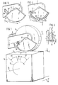
- the grinding wheel 2 can be seen, the axis 1 of which is arranged in an elongated component 3 consisting of two parallel arms.
- drives for the grinding wheel 2 are provided in the form of a belt pulley, not shown, via which a drive belt rotates, which mediates the drive of a motor located at the other end of the component 3.
- the grinding wheel 2 thus rotates about the grinding wheel axis 5, which runs parallel to the longitudinal axis 16 of the billet 14 to be machined.
- the stick 14 is displaced in the feed direction and rotated about its longitudinal axis 16 in the direction of the arrow 17 during this movement. This leads to the grinding wheel 2 machining the semifinished product surface 4, the penetration depth 6 of the machined semifinished product surface 4 being sufficient to prevent any cracks originally originating from the surface 4 from appearing.
- a segment 9 of a spiral forming the template is arranged on the grinding wheel bearing 10 on the side of the semi-finished surface 4 that has not yet been machined and can therefore be pivoted coaxially to the grinding wheel axis.
- a screw spindle 18 engages in the segment 9, for which a threaded block 12 is fastened to the component 3.
- the segment 9 can be set and determined in such a different way that the intended difference in height of the contact point 7 of the segment 9 with respect to the contact point of the grinding wheel 2 is maintained.
- the template 9 is on the opposite side.
- a further template 19 is provided on the side, in which the support point 13 lies on the already processed semi-finished surface 11 at the same height as for the grinding wheel 2. This results in an equally high support of the two-armed component 3 on both sides of the grinding wheel bearing 10 by means of the template 9 or 19 on the semifinished product surface 4 or 11.
- the further template 19 shown in Fig. 2 further allows that in an end position of the semi-finished product, when its feed is almost fully extended, there is also a support for the grinding wheel 2 when the opposite template is no longer on.
- the proposed height adjustability of the template can advantageously be controlled such that a change in distance occurs as a function of the angle of rotation, as a result of which the grinding wheel is raised in the corner area.
- a piston-cylinder unit 19, 20 is provided for the adjustability of the segment 9 designed as a stop.
- the cylinder is connected to a hydraulic control.
- the segment 9 is equipped with a roller 21.
- the circle segment is in this case of a somewhat smaller radius. It has an undercut groove track 29, indicated in the drawing, in which a screw nut, which cannot be seen in the drawing, is guided, so that the bearing bolt 30, which supports the roller 21, can be screwed in and tightened.
- the bearing roller 21 is fixed in a position as can be used for a limited height adjustment range of the segment 9.
- the segment 9 can be that of a circle and that of a spiral.
- the center of the circle 31 according to FIG. 1 lies at a short distance from the pivot bearing 32 of the segment passing through the grinding wheel axis 5, so that, based on the pivot point of the grinding wheel going through the grinding wheel axis 5 2, results in an eccentricity.
- the pivot bearing 32 can also be understood as the center of a spiral, of which the segment 9 represents a section. In this case, maintaining an eccentricity between the spiral center and the grinding wheel axis 5 is not indicated.
- the circumferential path of the segment 9 is largely identical in the drawing, as in the other case, so that a differentiated drawing has been dispensed with.
- the component 3 carrying the grinding wheel bearing is in turn pivotable in the fixed bearing block 33, so that the longitudinal center line 34 can assume different inclinations.
- the guide 35 has a scale for the purpose of setting a contact transmitter 23, which can be adjusted to a counter contact of the position transmitter 22.
- the highest and lowest position during the rotation of a stick can be read more easily on the position transmitter 22, so that, starting from the lowest position, the contact transmitter 23 can be adjusted to a certain altitude.
- the contactor is set to an altitude that is 2% above the lowest position.
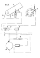
- a signal current leads directly from the contactor 23 to a switching switch 36 AND circuit 37.
- a signal current which flows via the switch 26 also leads to this switching switch 36.
- This switch 26 is under the influence of a switching cross 24 rotating with the stick 14, which moves a switch lever into its contact position during the rotation in the manner already described.
- the arrangement is expedient in such a way that there is a different switching state in the middle rotation region 28 by 20 ° than in the rotation region 27 of 35 ° which adjoins on both sides and extends to the corner.
- the two rotation regions 27, 28 mentioned are shown in FIG. 1.
- the AND circuit 37 allows either the contactor 23 or the switch 26 or both elements to be processed as an input signal by the switching switch 36 being set accordingly.
- the arithmetic amplifier 38 processes the received signal in such a way that, depending on the output of the arithmetic switch 38, the field controller 39 of a direct current bypass machine can be set to two different values such that the rotational speed of the drive motor 25 in the rotating range 27 is three times as large as in the rotating range 28 .
- FIG. 6 An optional arrangement for the semi-finished product to be driven at an uneven speed is shown in FIG. 6. Accordingly, there is an elliptical gear mechanism 40 which is connected via the gearwheel 41 to a drive motor rotating at the same speed. Together with the gearwheel 41, the toothed ellipse 42 rotates around its one focal point 43. It is in toothed engagement with the toothed ellipse 44 of the same size, which rotates around its one focal point 45. There is also a fixed connection between it and the driven gearwheel 46 . The latter drives the semi-finished gear 48, which has a fourfold circumference, so that four times the speed increases periodically when the latter rotates.
- the semi-finished product is in firm connection with the latter gear 48 in such a way that it is in the f turning regions 27 of the semi-finished product corners in relation to the rotating regions 28 ! r the middle of the semi-finished product comes to an increased speed 1 shows these areas.
- the extent of the non-uniformity can be selected by the choice of the eccentricity e and the large axis a of the two congruent elliptical gears, so that a correspondingly higher speed can be produced for the corner area than in the center area of the semi-finished product.
Landscapes
- Engineering & Computer Science (AREA)
- Mechanical Engineering (AREA)
- Grinding Of Cylindrical And Plane Surfaces (AREA)
- Grinding And Polishing Of Tertiary Curved Surfaces And Surfaces With Complex Shapes (AREA)
- Finish Polishing, Edge Sharpening, And Grinding By Specific Grinding Devices (AREA)
- Mechanical Treatment Of Semiconductor (AREA)
- Encapsulation Of And Coatings For Semiconductor Or Solid State Devices (AREA)
- Disintegrating Or Milling (AREA)
Abstract
Die Erfindung bezieht sich auf eine Vomcntung zum Schleifen von Halbzeug aus Stahl, insbesondere in Form von Knüppeln 14. Wenn die Knuppel 14 nicht nur in Längsrichtung zum Zwecke des Schleifens vorgeschoben werden, sondern darüber hinaus auch in ihrer Langsachse 16 gedreht werden, besteht die Gefahr, daß der Kantenbereich wegen der dort verlangerten Verweilzeit der Schleifscheibe 2 übermäßig stark abgetragen wird. Bekannte Ausgleichsverfahren tragen örtlichen Festigkeitsunterschieden im Werkstoff des Halbzeuges nicht hinreichend Rechnung Weiterhin finden in bekannter Weise mehrgliednge Anschlage Anwendung, welche keine genügend spielfreie Ubertragung eingestellter Eindringtiefen 6 gestatten. Um letztere auch bei Vorgabe niedriger Werte, die etwa 1 mm betragen, prazise mit einer konstruktiv einfachen und im Betrieb leicnt einstellbaren und zu wartenden Vorrichtung zu gewahrleisten, sieht die Erfindung für einen Anschlag in Form eines Segmentes 9 eines Kreises oder einer Spirale eine exzentrische bzw. koaxiale Lagerung zur Schleifscheibenachse vor, um welche das Segment 9 verschwenkbar ist, so daß es sich ein- und feststellen läßt. Dies führt zu einer Formsteuerung, die unmittelbar auf die Schleifscheibenachse 5 einwirkt, so daß die vorgegebene Eindringtiefe 6 genau einzuhalten ist.
Description
Die Erfindung bezieht sich auf eine Vorrichtung zum Schleifen von Halbzeug aus Stahl, insbesondere in Form von Knüppeln, bei denen eine Materialabtragung bis zur Eindringtiefe von oberflächennahen Rissen vorzunehmen ist, bestehend aus einer in ihrer Höhenläge relativ zum Halbzeug beweglichen Schleifscheibe, die mit ihrer Achse im wesentlichen parallel zur Längsachse des Halbzeuges angeordnet ist, während das Halbzeug zugleich in Richtung seiner Längsachse vorgeschoben und um letztere gedreht wird, und seine jeweilige Höhenlage von einem Anschlag erfaßt sowie auf die Schleifscheibe derart zur Einwirkung gebracht wird, daß sich eine über den gesamten Umfang vergleichmässigte Abtragung ergibt, wobei ein unmittelbar auf der noch nicht bearbeiteten Halbzeugoberfläche aufliegender, höhenverstellbarer Anschlag in Form eines Segmentes von etwa gleicher Krümmung wie die Schleifscheibe bezüglich der Schleifscheibenachse einen um die Eindringtiefe geringeren Abstand von seiner Auflagestelle als die Schleifscheibe aufweist.The invention relates to a device for grinding semi-finished products made of steel, in particular in the form of billets, in which material has to be removed to the depth of penetration of cracks near the surface, consisting of a grinding wheel which is movable in terms of its height relative to the semi-finished product and which has its axis in is arranged substantially parallel to the longitudinal axis of the semifinished product, while the semifinished product is simultaneously advanced in the direction of its longitudinal axis and rotated about the latter, and its respective height is detected by a stop and is brought to bear on the grinding wheel in such a way that one is uniform over the entire circumference Removal results, with a height-adjustable stop in the form of a segment of approximately the same curvature as the grinding wheel, lying directly on the not yet finished semi-finished product surface, with respect to the grinding wheel axis a distance from its support point that is smaller by the depth of penetration than d he grinding wheel.
Eine derartige Vorrichtung ist nach der US-PS 23 47 639 bekannt. Dabei ist ein bogenförmiger Anschlagschuh mittels einer Schraubspindel an einem Arm höhenverstellbar, der seinerseits an einem Träger befestigt ist. Der Träger greift wiederum an einem Hebel an, der das Lager der Schleifscheibe trägt. Eine derart mehrgliedrige Befestigung führt in der Praxis nicht nur zu einem aufwendigen konstruktiven Aufbau, sondern auch zu beträchtlichen übertragungsfehlern infolge der Maßabweichungen der einzelnen Glieder von ihren Sollwerten sowie bei ihrem zunehmenden Verschleiß, der unter den rauhen Betriebsbedingungen des Schleifens von Halbzeug aus Stahl beträchtlich ist.Such a device is known from US-
Auch ist nach der US-PS 25 58 943 eine ähnliche Vorrichtung zum Schleifen von Halbzeug aus Stahl bekannt. Hierbei befinden sich beidseitig von durchlaufenden, zu schleifenden Knüppeln aus Stahl Schalthebel, an welchen die Knüppelkanten beim Drehen zur Anlage kommen, und welche Schalter von Schaltkreisen auslösen, die mittels weiterer Schalter, für welche ein von auf den Flächen der Knüppel aufliegenden Tastfingern gesteuerter Nocken mit einer Betätigungsvorrichtung vorgesehen ist, die die Druckluftzufuhr zu Pneumatikzylindern steuern. Letztere sind mit ihrem einen Teil am Maschinenrahmen angeordnet, während ihr anderes Teil an einem Lagerarm der Schleifscheibe angreift, und somit den Schleifdruck in Abhängigkeit von der jeweiligen Drehstellung des Knüppels zu ändern gestattet. Diese Schleifdrucksteuerung ist derart ausgeführt, daß sich in Kantennähe der Anpreßdruck verringert, so daß entsprechend der dort bestehenden, längeren Verweilzeit ein Ausgleich geschaffen wird. Sofern die hierfür vorgegebene Abhängigkeit des Schleifdruckes von der Winkelstellung jedoch nicht den tatsächlichen funktionalen Gegebenheiten entspricht, kommt der beabsichtigte Ausgleich nur noch teilweise zustande. Insbesondere hängt der spezifische Schleifdruck weitgehend von der Materialzusammensetzung ab. Hinzu kommt noch, daß selbst bei Kenntnis aller übrigen Materialeinflüsse örtliche Festigkeitsunterschiede des Halbzeuges nicht feststellbar sind, die dann einen unzureichenden Ausgleich der Materialabtragung verursachen können.A similar device for grinding semi-finished steel products is also known from US Pat. No. 2,558,943. Here there are shifting levers made of steel on both sides of continuous, to be ground, on which the stick edges turn when turning System come, and trigger switches from circuits, which are provided by means of further switches, for which a cam controlled by touch fingers resting on the surfaces of the billets with an actuating device is provided, which control the compressed air supply to pneumatic cylinders. The latter are arranged with one part on the machine frame, while their other part engages on a bearing arm of the grinding wheel, and thus allows the grinding pressure to be changed as a function of the respective rotational position of the stick. This grinding pressure control is designed in such a way that the contact pressure is reduced near the edges, so that a compensation is created in accordance with the longer dwell time there. However, if the predetermined dependency of the grinding pressure on the angular position does not correspond to the actual functional conditions, the intended compensation will only be partially achieved. In particular, the specific grinding pressure largely depends on the material composition. In addition, even with knowledge of all other material influences, local differences in strength of the semi-finished product cannot be determined, which can then cause inadequate compensation for material removal.
Weiterhin ist nach der FR-PS 966 400 bekannt, beim Schleifen von Knüppeln den Kantendruck der Schleifscheibe mittels einer hydraulischen Ansteuerung herabzusetzen, die wiederum der Einwirkung eines hydraulischen Stellgliedes unterliegt, welches von einer Rolle beaufschlagt wird, die auf einer mit dem Knüppel umlaufenden Schablone aufliegt. Die tatsächlichen Knüppelabmessungen werden hierbei jedoch nicht erfaßt. Ferner unterliegt die Schleifdrucksteuerung von vorstehend bereits dargelegten Einwirkungen.Furthermore, according to FR-PS 966 400 it is known, when grinding billets, to reduce the edge pressure of the grinding wheel by means of a hydraulic control, which in turn is subject to the action of a hydraulic actuator which is acted upon by a roller which rests on a template rotating around the billet . However, the actual billet dimensions are not recorded here. Furthermore, the grinding pressure control is subject to the actions already described above.
Vom einleitend genannten Stand der Technik ausgehend liegt der Erfindung die Aufgabe zugrunde, für die Verlängerung der Aufenthaltszeit der Schleifscheibe im Kantenbereich des Knüppels bei der Drehung desselben eine konstruktiv besonders zuverlässige und einfache Anordnung mit verringertem Obertragungsfehlern zu treffen, die sich leicht einstellen lassen soll, um auch dem Abtrag des Schleifmittels der Schleifscheibe Rechnung zu tragen. Die Eindringtiefe der Materialabtragung soll auch bei unter- . schiedlicher Festigkeit des Werkstoffs gleichmäßig sein. Schließlich soll es auch möglich sein, die Voraussetzungen für die Erfassung der Drehstellung des Halbzeuges zu verbessern.On the basis of the prior art mentioned in the introduction, the invention is based on the object of making a structurally particularly reliable and simple arrangement with reduced transmission errors for the extension of the residence time of the grinding wheel in the edge region of the billet when rotating, which should be easy to adjust in order to also take into account the removal of the abrasive from the grinding wheel. The depth of penetration of material removal should also be different strength of the material must be uniform. Finally, it should also be possible to improve the conditions for detecting the rotational position of the semi-finished product.
Die Erfindung löst diese Aufgabenstellung durch die in den Patentansprüchen gekennzeichneten Vorschläge.The invention solves this problem by the proposals characterized in the claims.
Wie sich aus den Vorschlägen der Ansprüche 1 und 2 ergibt, besteht ein übereinstimmendes Merkmal der Erfindung darin, daß die Höhenverstellbarkeit des als Anschlag ausgebildeten Segmentes nicht durch eine vertikale Längsverschiebung desselben bewirkt wird, sondern auf der Grundlage einer Verschwenkbarkeit, indem das Schwenklager in unmittelbarer Nähe der Schleifscheibenachse oder sogar koaxial zu letzterer vorgesehen ist. Die Stellung des den Anschlag bildenden Segmentes wird bei einer derartigen Konstruktion unmittelbar bzw. mit geringstmöglichem Spiel auf das Lager der Schleifscheibe übertragen, so daß letztere mit hoher Präzision diejenige Materialabtragung vornimmt, die durch Einstellung des Segmentes vorgegeben wurde. Die Eindringtiefe wird demnach auch bei unterschiedlichen Werkstoffestigkeiten infolge Schwankungen der Zusammensetzung oder der Wärmebehandlung erreicht. Beim Schleifen von Knüppeln aus Stahl läßt sich das Segment derart einstellen, daß der Höhenunterschied etwa 1 mm beträgt.As is apparent from the proposals of
Die Bewegung des Halbzeuges in Längsrichtung einerseits und um die Längsachse andererseits führt zu einer leicht spiralförmigen Schleifspur, bei der sich die jeweilige Schleifbreite überdeckt.The movement of the semi-finished product in the longitudinal direction on the one hand and around the longitudinal axis on the other hand leads to a slightly spiral grinding track in which the respective grinding width overlaps.
Der Anstieg dieser Spiralbahn ist zwar nicht sehr ausgeprägt, jedoch ausreichend, um beim rechtwinkligen Schnitt, wie er bei . Halbzeugen sehr häufig ausgeführt werden muß, schräg zur Schnittlinie zu verlaufen. Daher können von Schleifspuren in Bezug auf senkrecht zur Längsachse des Halbzeuges abgescherte Abschnitte desselben keine Schäden, wie Schnittrisse oder dergleichen, ausgehen.The rise of this spiral path is not very pronounced, but it is sufficient for the right-angled cut as it is for. Semi-finished products must be carried out very often to run obliquely to the cutting line. Therefore, no damage, such as cut cracks or the like, can arise from grinding marks with respect to sections of the sheared off perpendicular to the longitudinal axis of the semi-finished product.
Die Gestaltung des Anschlages in Form eines Kreissegmentes ist technisch besonders leicht zu verwirklichen. Demgegenüber hat die Ausführungsform in Form eines Spiralsegmentes den Vorteil, auch größere Unterschiede in der Höhenlage erfassen zu können.The design of the stop in the form of a circular segment is technically particularly easy to implement. In contrast, the embodiment in the form of a spiral segment has the advantage of also being able to detect larger differences in altitude.
Der Verschleiß des Segmentes selbst kann man herabsetzen, indem die Schablone mit einer aufliegenden Laufrolle ausgeführt wird.The wear of the segment itself can be reduced by running the template with an overlying roller.
Die verschwenkbare Einstellung und Feststellung der Schablone läßt sich in unterschiedlicher Weise ausführen. Insbesondere ist sie auch der Automatisierung zugänglich, indem beispielsweise bei bekanntem Schleifmittelabtrag je Meter Knüppellänge eine laufende Nachstellung erfolgt. Im einfachsten Falle greift an der Schablone wenigstens eine Schraubspindel an, für die ein Gewindebock an dem das Schleifscheibenlager tragenden Bauteil vorgesehen ist. Die Schraubspindel kann dann jweils von Hand in der gewünschten Weise verstellt werden.The pivotable setting and fixing of the template can be carried out in different ways. In particular, it is also accessible to automation by, for example, a constant readjustment per meter stick length when the abrasive is removed. In the simplest case, at least one screw spindle acts on the template, for which a threaded bracket is provided on the component carrying the grinding wheel bearing. The screw spindle can then be adjusted in the desired manner by hand.
In entsprechender Weise läßt sich eine Kolben-Zylinder-Einheit verwenden, deren eines Teil an der Schablone und deren anderes Teil an dem das Schleifscheibenlager tragenden Bauteil angreift.In a corresponding manner, a piston-cylinder unit can be used, one part of which engages the template and the other part of which engages the component carrying the grinding wheel bearing.
Die Schleifscheibe besitzt im Normalfall eine zylindrische Bearbeitungsfläche. Da die Abtragung in einer Ebene erfolgen soll, ist demgemäß erforderlich, daß die Längsachse des Halbzeuges und die Schleifscheibenachse parallel zueinander verlaufen. Die Auflagestellen der Schleifscheibe einerseits und der Schablone andererseits können jedoch unter ungünstigen Umständen, das heißt bei nicht hinreichend fester Anordnung der das Schleifscheibenlager tragenden Bauteile, zu einer leichten Schrägstellung der Schteifscheibenachse Anlaß geben. Dies läßt sich vermeiden, wenn auch auf der bearbeiteten Halbzeugoberfläche liegenden Seite der Schleifscheibe eine Schablone vorgesehen wird, die dann allerdings mit gleicher Höhenlage, bezogen auf die Schleifscheibenachse, auf der Schleifscheibe aufliegt.The grinding wheel normally has a cylindrical machining surface. Since the removal is to take place in one plane, it is accordingly necessary that the longitudinal axis of the semi-finished product and the grinding wheel axis run parallel to one another. The contact points of the grinding wheel on the one hand and the template on the other hand can, however, not go under unfavorable circumstances Sufficiently firm arrangement of the components supporting the grinding wheel bearing give rise to a slight inclination of the grinding wheel axis. This can be avoided if a template is also provided on the machined side of the grinding wheel lying on the finished semi-finished product surface, which, however, then rests on the grinding wheel at the same height relative to the grinding wheel axis.
Die Erfindung sieht weiterhin die Verwendung von Mitteln für die Erfassung der Drehstellung des Halbzeuges vor. Diese können in ihrer Wirkungsweise unmittelbar von der Ausbildung des Anschlages beeinflußt werden, wenn an dem das Lager der Schleifscheibe tragenden Bauteil ein Stellungsgeber vorgesehen wird, auf welchen ein Kontaktgeber einstellbar ist. Man kann die Anordnung insbesondere derart treffen, daß der Stellungsgeber den Kontaktgeber erreicht, wenn sich die Höhenlage des Segmentes um mehr als 2 %, ausgehend von seiner tiefsten Stellung, angehoben hat. Als tiefste Stellung wird dabei diejenige angesehen, in welcher das Segment in der Mitte des Halbzeuges zwischen zwei Kanten aufliegt. Die -Anhebung von mehr als 2 % entspricht einem mittleren Drehbereich von etwa 20° und einem die Ecken überdeckenden Drehbereich von etwa 70°.The invention further provides for the use of means for detecting the rotational position of the semi-finished product. Their mode of operation can be directly influenced by the design of the stop if a position transmitter is provided on the component bearing the grinding wheel, on which a contact transmitter can be set. The arrangement can in particular be made such that the position transmitter reaches the contact transmitter when the height of the segment has increased by more than 2%, starting from its lowest position. The lowest position is considered to be the one in which the segment lies in the middle of the semi-finished product between two edges. The increase of more than 2% corresponds to an average rotation range of approximately 20 ° and a rotation range covering the corners of approximately 70 °.
Zur Erfassung der Drehstellung läßt sich in bekannter Weise auch ein Schaltkreuz verwenden, welche mit dem Halbzeug umläuft, nach jeweils 90° Drehung einen Schalter einschaltet und diesen für weniger als 90° Drehung eingeschaltet hält.To detect the rotational position, a switching cross can also be used in a known manner, which rotates with the semi-finished product, switches on a switch after every 90 ° rotation and keeps it switched on for less than 90 ° rotation.
In jedem Falle ist es zweckmäßig, wenn der Kontaktgeber oder der Schalter die Drehgeschwindigkeit des Halbzeuges im Drehbereich von cirka 35°, von jeder Ecke des Halbzeuges ausgehend, 3-fach so schnell wie im sich anschließenden 20° betragenden Drehbereich in Halbzeugmitte eingeschaltet hält.In any case, it is expedient if the contactor or the switch keeps the speed of rotation of the semi-finished product in the rotating range of approximately 35 °, starting from each corner of the semi-finished product, 3 times as fast as in the subsequent 20 ° rotating range in the middle of the semi-finished product.
Schließlich läßt sich noch eine Höhenverstellbarkeit des Anschlages in Abhängigkeit vom Drehwinkel des Halbzeuges gestalten, und zwar mit der Maßgabe, daß sich die Schleifscheibe im Bereich der Ecken des Halbzeuges etwas anhebt.Finally, the stop can be adjusted in height as a function of the angle of rotation of the semi-finished product, with the proviso that the grinding wheel lifts somewhat in the region of the corners of the semi-finished product.
Man kann weiterhin die Ungleichförmigkeit des Antriebs bei Knüppeln auch dadurch erreichen, daß ein mit gleichförmiger Geschwindigkeit angetriebenes Ellipsenrädergetriebe vorgesehen wird. Abtriebsseitig ist hierbei ein Zahnrad mit vierfachem Umfang gegenüber demjenigen des Abtriebszahnrades angeordnet, welches drehfest mit dem Halbzeug in Verbindung steht. Somit wird bei einmaligem Umlauf des letzteren in vier Bereichen die Geschwindigkeit erhöht. Die Einspannung erfolgt derart, daß diese letzgenannten Bereiche die Bereiche der Ecken des Halbzeuges sind.You can also achieve the non-uniformity of the drive in billets by providing an elliptical gear driven at a uniform speed. On the output side, a gearwheel with a fourfold circumference is arranged relative to that of the output gearwheel, which is non-rotatably connected to the semi-finished product. Thus, the speed is increased in four areas when the latter rotates once. The clamping takes place in such a way that these latter areas are the areas of the corners of the semi-finished product.
Zur weiteren Veranschaulichung der Erfindung wird auf die sich auf Ausführungsbeispiele beziehenden Zeichnungen Bezug genommen..To further illustrate the invention, reference is made to the drawings relating to exemplary embodiments.
Darin zeigt:
- Fig. 1 eine isometrische Darstellung der erfindungsgemäßen Vorrichtung,
- Fig. 2 eine schematische Vorderansicht auf die Schleifscheibe,
- Fig. 3 eine geänderte Ausführungsform der Höhenverstellbarkeit des als Segment ausgeführten Anschlages,
- Fig. 4 eine weitere geänderte Ausführungsform des als Segment ausgeführten Anschlages,
- Fig. 5 ein Blockschaltbild für die Umstellung der Drehgeschwindigkeit des Halbzeugs in Abhängigkeit von der Drehstellung desselben und
- Fig. 6 eine wahlweise Ausführungsform für die ungleichförmige Drehgeschwindigkeit des Halbzeuges.
- 1 is an isometric view of the device according to the invention,
- 2 is a schematic front view of the grinding wheel,
- 3 shows a modified embodiment of the height adjustability of the stop designed as a segment,
- 4 shows a further modified embodiment of the stop designed as a segment,
- Fig. 5 is a block diagram for the change in the rotational speed of the semi-finished product depending on the rotational position of the same and
- Fig. 6 shows an optional embodiment for the non-uniform rotational speed of the semi-finished product.
Zeichnungsgemäß erkennt man die Schleifscheibe-2, deren Achse 1 in einen langgestreckten, aus zwei parallelen Armen bestehenden Bauteil 3 angeordnet ist. Zusätzlich sind Antriebe für die Schleifscheibe 2 in Form einer nicht dargestellten Riemenscheibe vorgesehen, über die ein Antriebsriemen umläuft, der den Antrieb eines am anderen Ende des Bauteils 3 befindlichen Motors vermittelt.According to the drawing, the
Somit dreht sich die Schleifscheibe 2 um die Schleifscheibenachse 5, die parallel zur Längsachse 16 des zu bearbeitenden Knüppels 14 verläuft. Der Knüppel 14 wird dabei in Vorschubrichtung verschoben sowie während dieser Bewegung um seine Längsachse 16 in Richtung des Pfeils 17 gedreht. Dies führt dazu, daß die Schleifscheibe 2 die Halbzeugoberfläche 4 abtragend bearbeitet, wobei die Eindringtiefe 6 der bearbeiteten Halbzeugoberfläche 4 ausreichend ist, um keine von der Oberfläche 4 ursprünglich ausgehenden Risse näher in Erscheinung treten zu lassen.The
Am Schleifscheibenlager 10 ist auf der Seite der noch nicht bearbeiteten Halbzeugoberfläche 4 ein die Schablone bildendes Segment 9 einer Spirale angeordnet, das mithin koaxial zur Schleifscheibenachse verschwenkbar ist. Um eine Einstellung und Feststellung vornehmen zu können, greift in das Segment 9 eine Schraubspindel 18 ein, für die ein Gewindeblock 12 am Bauteil 3 befestigt ist. Durch Verdrehen der Schraubspindel 12 läßt sich das Segment 9 derart unterschiedlich einstellen und feststellen, daß der vorgesehene Höhenunterschied der Auflagestelle 7 des Segmentes 9 gegenüber der Auflagestelle der Schleifscheibe 2 eingehalten wird.A segment 9 of a spiral forming the template is arranged on the grinding wheel bearing 10 on the side of the
Aus den bereits erwähnten Gründen der Stabilisierung der Schleifscheibenachse 5 ist auf der der Schablone 9 gegenüberliegenden . Seite eine weitere Schablone 19 vorgesehen, bei welcher die Auflagestelle 13 auf der bereits bearbeiteten Halbzeugoberfläche 11 in gleicher Höhe wie bei der Schleifscheibe 2 liegt. Somit ergibt sich zu beiden Seiten des Schleifscheibenlagers 10 eine gleich hohe Abstützung des zweiarmigen Bauteils 3 mittels der Schablone 9 bzw. 19 auf der Halbzeugoberfläche 4 bzw. 11.For the reasons already mentioned for stabilizing the
Die in Fig. 2 dargestellte weitere Schablone 19 ermöglicht weiterhin, daß in einer Endlagenstellung des Halbzeuges, wenn dessen Vorschub nahezu ganz ausgefahren ist, auch noch eine Abstützung für die Schleifscheibe 2 besteht, wenn die gegenüberliegende Schablone nicht mehr aufliegt.The
Die vorgeschlagene Höhenverstellbarkeit der Schablone läßt sich in vorteilhafter Weise noch derart steuern, daß in Abhängigkeit vom Drehwinkel eine Abstandsveränderung eintritt, als deren Folge die Schleifscheibe im Eckbereich angehoben wird.The proposed height adjustability of the template can advantageously be controlled such that a change in distance occurs as a function of the angle of rotation, as a result of which the grinding wheel is raised in the corner area.
Gemäß Fig. 3 ist für die Verstellbarkeit des als Anschlag ausgebildeten Segmentes 9 eine Kolben-Zylinder-Einheit 19, 20 vorgesehen. Deren eines Teil 19, nämlich die Kolbenstange, greift am Segment 9 an, wchingegen deren anderes Teil 20, nämlich der Zylinder, an dem das Schleifscheibenlager 10 tragenden Bauteil 3 angelenkt ist. Der Zylinder ist an einer hydraulischen Steuerung angeschlossen.According to FIG. 3, a piston-
Bei der Ausführungsform nach Fig. 4 ist das Segment 9 mit einer Laufrolle 21 ausgestattet. Das Kreissegment ist in diesem Falle von etwas geringerem Radius. Es besitzt eine zeichnungsgemäß angedeutete, hinterschnittene Nutbahn 29 in welcher eine zeichnerisch nicht erkennbare Schraubmutter geführt ist, so daß der Lagerbolzen 30, der die Laufrolle 21 lagert, ein- und festgeschraubt werden kann. Die Lagerrolle 21 wird jeweils in einer Stellung fixiert, wie sie für einen begrenzten Höheneinstellbereich des Segmentes 9 anwendbar ist.In the embodiment according to FIG. 4, the segment 9 is equipped with a
In der vorgeschlagenen Weise kann das Segment 9 dasjenige eines Kreises sowie auch dasjenige einer Spirale sein. Für den Fall, daß es sich um ein Kreissegment handelt, liegt der Kreismittelpunkt 31 entsprechend Fig. 1 mit einem geringen Abstand vom durch die Schleifscheibenachse 5 gehenden Schwenklager 32 des Segmentes, so daß sich, bezogen auf den durch die Schleifscheibenachse 5 gehenden Drehpunkt der Schleifscheibe 2, eine Exzentrizität ergibt. Das Schwenklager 32 kann indes auch als der Mittelpunkt einer Spirale aufgefaßt werden, von welcher das Segment 9 einen Ausschnitt darstellt. Für diesen Fall ist die Einhaltung einer Exzentrizität zwischen dem Spiralenmittelpunkt und der Schleifscheibenachse 5 nicht angezeigt. Die Umfangsbahn des Segmentes 9 ist im einen wie im anderen Falle zeichnerisch weitgehend übereinstimmend, so daß von einer differenzierten Zeichnung abgesehen wurde.In the proposed manner, the segment 9 can be that of a circle and that of a spiral. In the event that it is a segment of a circle, the center of the
Das das Schleifscheibenlager tragende Bauteil 3 ist seinerseits im ortsfesten Lagerbock 33 verschwenkbar, so daß die Längsmittellinie 34 unterschiedliche Neigungen einnehmen kann.The
Ein in einer FUhrung 35 verschieblicher, skalierter Stellungsgeber 22 ist an dem das Schleifscheibenlager tragende Bauteil 3 angelenkt, während die Führung 35 ortsfest angelenkt ist. Die Führung 35 besitzt eine Skala zwecks Einstellung eines Kontaktgebers 23, der auf einen Gegenkontakt des Stellungsgebers 22 eingestellt werden kann. In der Praxis läßt sich die höchste und niedrigste Stellung beim Umlauf eines Knüppels leichter am Stellungsgeber 22 ablesen, so daß, von der niedrigsten Stellung ausgehend, der Kontaktgeber 23 auf eine bestimmte Höhenlage einstellbar ist. Wie erwähnt, ist es zweckmäßig, wenn der Kontaktgeber auf eine Höhenlage eingestellt wird, die 2 % über der niedrigsten Stellung liegt. Vom Kontaktgeber 23 führt ein Signalstrom unmittelbar zu einer Schaltweiche 36 einer UND-Schaltung 37. Zu dieser Schaltweiche 36 führt weiterhin ein Signalstrom, der über den Schalter 26 fließt. Dieser Schalter 26 -steht unter der Einwirkung eines mit dem Knüppel 14 umlaufenden Schaltkreuzes 24, welches einen Schalterhebel beim Umlauf in der bereits beschriebenen Weise in seine Kontaktstellung überführt. Zweckmäßig ist die Anordnung derart, daß sich bei dem mittleren Drehbereich 28 um 20° ein anderer Schaltzustand als in dem sich beideitig anschließenden, bis zur Ecke reichenden Drehbereich 27 von je 35° besteht. Die genannten beiden Drehbereiche 27, 28 sind der Übersichtlichkeit halber in Fig. 1 eingezeichnet.A
Die UND-Schaltung 37 gestattet es, wahlweise den Kontaktgeber 23 oder den Schalter 26 oder beide Elemente als Eingangssignal zu verarbeiten, indem die Schaltweiche 36 entsprechend eingestellt wird. Der Rechenverstärker 38 verarbeitet das empfangene Signal derart, daß sich in Abhängigkeit vom Ausgang des Rechenschalters 38 der Feldregler 39 einer Gleichstrom-Nebenflußmaschine auf zwei unterschiedliche Werte derart einstellen läßt, daß die Drehgeschwindigkeit des Antriebsmotors 25 im Drehbereich 27 dreimal so groß wie im Drehbereich 28 ist.The AND
Eine wahlweise Anordnung für das mit ungleicher Geschwindigkeit anzutreibende Halbzeug zeigt Fig. 6. Demnach besteht ein Ellipsenrädergetriebe 40, welches über das Zahnrad 41 mit einem mit gleicher Geschwindigkeit umlaufenden Antriebsmotor in Verbindung steht. Zusammen mit dem Zahnrad 41 dreht sich die verzahnte Ellipse 42 um ihren einen Brennpunkt 43. Sie steht im verzahnten Eingriff mit der gleich großen, verzahnten Ellipse 44, die um ihren einen Brennpunkt 45 umläuft.Ferner besteht zwischen ihr und dem Abtriebszahnrad 46 eine feste Verbindung. Letzteres treibt das mit vierfachem Umfang ausgeführte Halbzeugzahnrad 48, so daß sich bei einer Umdrehung des letzteren periodisch viermalige Geschwindigkeitsteigerungen ergeben. Mit dem letztgenannten Zahnrad 48 steht das Halbzeug in fester Verbindung derart, daß es in den Drehbereichen 27 der Halbzeugecken gegenüber den Drehbereichen 28 in df!r Halbzeugmitte zu einer erhöhten Geschwindigkeit kommt. Diese Bereiche zeigt Fig. 1.An optional arrangement for the semi-finished product to be driven at an uneven speed is shown in FIG. 6. Accordingly, there is an
Das Ausmaß der Ungleichförmigkeit läßt sich durch die Wahl der Exzentrizität e sowie der großen Achse a der beiden kongruenten Ellipsenzahnräder wählen, so daß sich auf diese Weise für den Eckbereich eine entsprechend höhere Geschwindigkeit als im Mittenbereich des Halbzeuges herstellen läßt.The extent of the non-uniformity can be selected by the choice of the eccentricity e and the large axis a of the two congruent elliptical gears, so that a correspondingly higher speed can be produced for the corner area than in the center area of the semi-finished product.
Claims (13)
dadurch gekennzeichnet,
daß für das als Anschlag ausgebildete Segment (9) eines Kreises an dem das Schleifscheibenlager (10) aufweisenden Bauteil eine zur Schleifscheibenachse (5) exzentrische Lagerung besteht, um welche das Segment (9) verschwenkbar ein- und feststellbar ist:1. Device for grinding semi-finished products made of steel, in particular in the form of billets (14), in which material has to be removed up to the depth of penetration of near-surface cracks, consisting of a grinding wheel (22) that is movable in relation to its height relative to the semi-finished product Axis (5) is arranged substantially parallel to the longitudinal axis (16) of the semifinished product, while the semifinished product is simultaneously advanced in the direction of its longitudinal axis and rotated about the latter, and its respective height is detected by a stop and act on the grinding wheel (2) in this way is brought about that there is an even removal over the entire circumference, whereby a height-adjustable stop in the form of a segment (9) of approximately the same curvature as the grinding wheel (2) with respect to the grinding rests directly on the not yet processed semi-finished surface (4) -. disc axis (5) has a smaller penetration depth (6) from its support point than the grinding wheel (2),
characterized,
that for the segment (9) formed as a stop on a circle on the component having the grinding wheel bearing (10), there is an eccentric bearing to the grinding wheel axis (5), about which the segment (9) can be pivoted and locked:
daß der Anschlag als Segment (9) einer Spirale ausgebildet ist, das an dem das Schleifscheibenlager (10) aufweisenden Bauteil koaxial zur Schleifscheibenachse (5) verschwenkbar ein- und feststellbar ist.2. Device according to the preamble of claim 1, characterized in that
that the stop is designed as a segment (9) of a spiral, which can be pivoted and locked on the component having the grinding wheel bearing (10) coaxially to the grinding wheel axis (5).
daß der Anschlag eine aufliegende Laufrolle (21) aufweist.3. Device according to claim 1, characterized in that
that the stop has an overlying roller (21).
daß für die Verstellbarkeit des Anschlages wenigstens eine an ihm angreifende Schraubspindel (18) vorgesehen ist, für die ein Gewindebock (12) an dem das Schleifscheibenlager (10) tragenden Bauteil (3) besteht.4. Device according to claims 1 to 3, characterized in
that for the adjustability of the stop at least one screw spindle (18) engaging it is provided, for which there is a threaded bracket (12) on the component (3) carrying the grinding wheel bearing (10).
daß für die Verstellbarkeit des Anschlages wenigstens ein Teil (19) einer an ihm angreifende Kolben-Zylinder-. Einheit (19, 20) vorgesehen ist, deren anderes Teil (20) an dem das Schleifscheibenlager- (10) tragenden Bauteil (3) vorgesehen ist.5. Device according to claims 1 to 3, characterized in
that for the adjustability of the stop at least a part (19) of a piston-cylinder acting on it. Unit (19, 20) is provided, the other part (20) of which is provided on the component (3) carrying the grinding wheel bearing (10).
daß auf der zur bereits bearbeiteten Halbzeugoberfläche (11) weisenden Seite der Schleifscheibe (2) an dem das Lager (1) der Schleifscheibe (2) tragenden Bauteil (3) ein unmittelbar aufliegender Anschlag (19) befestigt ist, bei dem der Abstand zwischen der Auflagestelle (13) und der Schleifscheibenachse (5) gleich so groß wie bei der Schleifscheibe (8) ist.6. Device according to claims 1 to 5, characterized in
that on the already processed semi-finished surface (11) side of the grinding wheel (2) on which the bearing (1) of the grinding wheel (2) carrying component (3) is attached a directly resting stop (19), in which the distance between the Support point (13) and the grinding wheel axis (5) is the same size as for the grinding wheel (8).
daß Mittel für die Erfassung der Drehstellung des Halbzeuges vorgesehen sind.7. Device according to claims 1 to 6, characterized in
that means are provided for detecting the rotational position of the semi-finished product.
daß für die Erfassung der Drehstellung an dem das Lager (10) der Schleifscheibe (2) tragenden Bauteil (3) ein Stellungsgeber (22) vorgesehen ist, auf den ein Kontaktgeber (23) einstellbar ist.8. The device according to claim 7, characterized in that
that for detecting the rotational position on the bearing (10) of the grinding wheel (2) supporting component (3) a position transmitter (22) is provided, on which a contact transmitter (23) can be adjusted.
daß der Stellungsgeber (22) den Kontaktgeber (23) erreicht, wenn sich die Höhenlage des Segmentes (9) um mehrals 2 %, ausgehend von seiner tiefsten Stellung, angehoben hat.9. The device according to claim 8, characterized in
that the position transmitter (22) reaches the contact transmitter (23) when the height of the segment (9) has increased by more than 2%, starting from its lowest position.
daß für die Erfassung der Drehstellung ein Schaltkreuz (24) mit dem Halbzeug umlaufend in Verbindung steht, welches nach jeweils 90° Drehung einen Schalter (26) einschaltet und für weniger als 90° Drehung eingeschaltet hält.10. The device according to claim 7, characterized in
that for the detection of the rotational position, a switching cross (24) is connected to the semifinished product, which switches on a switch (26) after every 90 ° rotation and keeps it switched on for less than 90 ° rotation.
daß der Kontaktgeber (23) und/oder der Schalter (26) die Drehgeschwindigkeit des Halbzeuges im Drehbereich (27) von je cirka 35°, von jeder Ecke des Halbzeuges ausgehend, etwa 3-fach so schnell wie im cirka 20° betragenden Drehbereich (28) der Halbzeugmitte eingeschaltet hält.11. The device according to claims 7 to 10, characterized in that
that the contactor (23) and / or the switch (26) the speed of rotation of the semi-finished product in the rotating range (27) of approximately 35 °, starting from each corner of the semi-finished product, approximately 3 times as fast as in the approximately 20 ° rotating range ( 28) the middle of the semi-finished product keeps on.
daß die Höhenverstellbarkeit des als Anschlag ausgebildeten Segmentes (9) in Abhängigkeit vom Drehbereich (27, 28) des Halbzeuges mit der Maßgabe erfolgt, daß sich die Schleifscheibe (2) im Bereich der Ecken des Halbzeuges anhebt.12. The device according to claims 1 to 11, characterized in that
that the height adjustability of the segment (9) designed as a stop is dependent on the range of rotation (27, 28) of the semifinished product, with the proviso that the grinding wheel (2) lifts in the area of the corners of the semifinished product.
daß Mittel für die Veränderbarkeit der Drehgeschwindigkeit des Halbzeuges in Form eines Ellipsenrädergetriebes vorgesehen sind, für welches eintriebsseitig ein Antriebsmotor und abtriebsseitig ein Übersetzungszahnrad mit vierfachem Umfang besteht, welch letzteres drehfest mit dem im Drehbereich (27) seiner Ecken schneller als im Drehbereich (28) seiner Mitten anzutreibenden Halbzeug verbunden ist.13. Device according to claims 1 to 6, characterized in that
that means for changing the speed of rotation of the semifinished product are provided in the form of an elliptical gear, for which there is a drive motor on the input side and a transmission gear with a quadruple circumference on the output side, the latter being rotatably fixed with the one in the turning area (27) of its corners faster than in the turning area (28) of its Middle driven semi-finished product is connected.
Priority Applications (1)
| Application Number | Priority Date | Filing Date | Title |
|---|---|---|---|
| AT86105987T ATE77783T1 (en) | 1985-05-14 | 1986-04-30 | DEVICE FOR GRINDING SEMI-FINISHED PRODUCTS. |
Applications Claiming Priority (2)
| Application Number | Priority Date | Filing Date | Title |
|---|---|---|---|
| DE3517302 | 1985-05-14 | ||
| DE19853517302 DE3517302A1 (en) | 1985-05-14 | 1985-05-14 | DEVICE FOR GRINDING SEMI-PRODUCTS |
Publications (3)
| Publication Number | Publication Date |
|---|---|
| EP0201810A2 true EP0201810A2 (en) | 1986-11-20 |
| EP0201810A3 EP0201810A3 (en) | 1989-08-23 |
| EP0201810B1 EP0201810B1 (en) | 1992-07-01 |
Family
ID=6270673
Family Applications (1)
| Application Number | Title | Priority Date | Filing Date |
|---|---|---|---|
| EP86105987A Expired - Lifetime EP0201810B1 (en) | 1985-05-14 | 1986-04-30 | Device for grinding a semi-finished product |
Country Status (4)
| Country | Link |
|---|---|
| US (1) | US4679355A (en) |
| EP (1) | EP0201810B1 (en) |
| AT (1) | ATE77783T1 (en) |
| DE (2) | DE3517302A1 (en) |
Families Citing this family (3)
| Publication number | Priority date | Publication date | Assignee | Title |
|---|---|---|---|---|
| JP6900019B2 (en) * | 2016-05-25 | 2021-07-07 | 株式会社ナガセインテグレックス | Grinding method for polyhedral workpieces |
| US10058976B2 (en) | 2016-11-11 | 2018-08-28 | Att Technology, Ltd. | Hardbanding removal device and method |
| CN115502858A (en) * | 2022-09-21 | 2022-12-23 | 马鞍山市鑫龙特钢有限公司 | Steel pipe blank surface treatment device |
Family Cites Families (16)
| Publication number | Priority date | Publication date | Assignee | Title |
|---|---|---|---|---|
| DE138615C (en) * | ||||
| DE138618C (en) * | ||||
| US2347639A (en) * | 1942-11-24 | 1944-04-25 | Driver Co Wilbur B | Bar-grinding apparatus |
| US2347503A (en) * | 1943-08-27 | 1944-04-25 | Driver Co Wilbur B | Bar-grinding apparatus |
| FR966400A (en) * | 1948-05-13 | 1950-10-09 | Pressure regulator device applicable to ingot grinding | |
| US2558943A (en) * | 1949-11-15 | 1951-07-03 | Driver Co Wilbur B | Bar grinding apparatus |
| GB831652A (en) * | 1956-08-10 | 1960-03-30 | Matisa Materiel Ind Sa | Grinding machine for rails, beams and like members |
| US2876598A (en) * | 1957-01-10 | 1959-03-10 | Allegheny Ludlum Steel | Grinding machine |
| US3040481A (en) * | 1960-09-16 | 1962-06-26 | Vlieg Howard Rawson De | Ice skate grinding machine |
| DE1272769B (en) * | 1964-11-07 | 1968-07-11 | Juenkerather Maschbau Gmbh | Pendulum grinding machine for all-round grinding or fault grinding of billets or similar semi-finished products that can be reversed parallel to the grinding wheel axis |
| US3823617A (en) * | 1972-04-28 | 1974-07-16 | Aqua Marine Mfg Ltd | Steering system |
| DE2336276C2 (en) * | 1972-07-21 | 1982-11-25 | Nolek System AB, Norsborg | Fettling unit for identical casting series - has grinding disc with work stops and rectifying roller adjustable by common screw spindle |
| HU167643B (en) * | 1973-04-24 | 1975-11-28 | ||
| US3918209A (en) * | 1974-08-19 | 1975-11-11 | British Oxygen Co Ltd | Metal removal apparatus |
| FR2460182A1 (en) * | 1979-06-29 | 1981-01-23 | Gendron Sa | DEVICE FOR MACHINING CAMES WITH PRECISION AND CONSTANT CUTTING SPEED |
| DE3312898A1 (en) * | 1983-04-11 | 1984-10-11 | Vereinigte Glaswerke Gmbh, 5100 Aachen | Method and device for position control of the tool of an edge-grinding machine for glass panes |
-
1985
- 1985-05-14 DE DE19853517302 patent/DE3517302A1/en active Granted
-
1986
- 1986-04-30 DE DE8686105987T patent/DE3685854D1/en not_active Expired - Lifetime
- 1986-04-30 AT AT86105987T patent/ATE77783T1/en not_active IP Right Cessation
- 1986-04-30 EP EP86105987A patent/EP0201810B1/en not_active Expired - Lifetime
- 1986-05-13 US US06/862,653 patent/US4679355A/en not_active Expired - Fee Related
Also Published As
| Publication number | Publication date |
|---|---|
| DE3517302C2 (en) | 1988-02-04 |
| ATE77783T1 (en) | 1992-07-15 |
| US4679355A (en) | 1987-07-14 |
| DE3685854D1 (en) | 1992-08-06 |
| EP0201810A3 (en) | 1989-08-23 |
| DE3517302A1 (en) | 1986-11-20 |
| EP0201810B1 (en) | 1992-07-01 |
Similar Documents
| Publication | Publication Date | Title |
|---|---|---|
| DE1502416C2 (en) | Grinding device for the grinding wheel of a roll grinder. Eliminated from: 1427485 | |
| DE2612174B2 (en) | Rail grinding machine for grinding irregularities in the rail runway | |
| DE3416664C2 (en) | Device for controlling the cutting speed of the saw blade of a band saw machine | |
| DE3049171C2 (en) | ||
| DE2523225C2 (en) | Sanding machine, in particular for sanding wooden parts | |
| EP0241892A2 (en) | Belt sander | |
| DE2616401C2 (en) | ||
| DE1777187B2 (en) | CENTERLESS GRINDING MACHINE FOR GRINDING LONG STRETCHED BARS OF DIFFERENT DIAMETERS IN A CONTINUOUS PROCESS | |
| DE19756503B4 (en) | moulder | |
| DE2948719C2 (en) | Knife roller machine for processing hides and skins | |
| EP0201810B1 (en) | Device for grinding a semi-finished product | |
| WO2010006572A1 (en) | Strand pelletizer with cutting clearance adjustment | |
| DE2827917C2 (en) | Grinding machine for rounding the corners of rectangular, plate-shaped workpieces | |
| DE1652220C3 (en) | Process for machining a workpiece | |
| DE2505985C3 (en) | Saw sharpening machine for sharpening teeth of different tooth tip heights | |
| EP0495354A1 (en) | Device for treating fabric-like workpieces, in particular of leather or the like | |
| DE2807183B2 (en) | Machine for cutting wire ends on assembled circuit boards | |
| DE3011786C2 (en) | ||
| DE2452233A1 (en) | CONTOUR GRINDING MACHINE | |
| DE3815639C2 (en) | ||
| DE3048253A1 (en) | Ski bearing edge sharpener - consists of slide rings mounted on rods sliding in transverse holes in support | |
| EP1279453A2 (en) | Rotary cutting device and adjusting device and rotary cutting head for such a rotary cutting device | |
| EP0510623B1 (en) | Resharpening machine | |
| DE3815130A1 (en) | Device for advancing grinding discs of a rotation hoop knife splitting machine | |
| DE1076469B (en) | Equipment on gear grinding machines for longitudinal crown grinding of straight and helical gears |
Legal Events
| Date | Code | Title | Description |
|---|---|---|---|
| PUAI | Public reference made under article 153(3) epc to a published international application that has entered the european phase |
Free format text: ORIGINAL CODE: 0009012 |
|
| AK | Designated contracting states |
Kind code of ref document: A2 Designated state(s): AT BE CH DE FR GB IT LI LU NL SE |
|
| PUAL | Search report despatched |
Free format text: ORIGINAL CODE: 0009013 |
|
| AK | Designated contracting states |
Kind code of ref document: A3 Designated state(s): AT BE CH DE FR GB IT LI LU NL SE |
|
| 17P | Request for examination filed |
Effective date: 19890923 |
|
| 17Q | First examination report despatched |
Effective date: 19910326 |
|
| GRAA | (expected) grant |
Free format text: ORIGINAL CODE: 0009210 |
|
| AK | Designated contracting states |
Kind code of ref document: B1 Designated state(s): AT BE CH DE FR GB IT LI LU NL SE |
|
| PG25 | Lapsed in a contracting state [announced via postgrant information from national office to epo] |
Ref country code: SE Effective date: 19920701 Ref country code: NL Effective date: 19920701 |
|
| REF | Corresponds to: |
Ref document number: 77783 Country of ref document: AT Date of ref document: 19920715 Kind code of ref document: T |
|
| REF | Corresponds to: |
Ref document number: 3685854 Country of ref document: DE Date of ref document: 19920806 |
|
| ITF | It: translation for a ep patent filed | ||
| GBT | Gb: translation of ep patent filed (gb section 77(6)(a)/1977) | ||
| ET | Fr: translation filed | ||
| NLV1 | Nl: lapsed or annulled due to failure to fulfill the requirements of art. 29p and 29m of the patents act | ||
| PG25 | Lapsed in a contracting state [announced via postgrant information from national office to epo] |
Ref country code: LU Free format text: LAPSE BECAUSE OF NON-PAYMENT OF DUE FEES Effective date: 19930430 Ref country code: LI Effective date: 19930430 Ref country code: GB Effective date: 19930430 Ref country code: CH Effective date: 19930430 Ref country code: BE Effective date: 19930430 Ref country code: AT Effective date: 19930430 |
|
| PLBE | No opposition filed within time limit |
Free format text: ORIGINAL CODE: 0009261 |
|
| STAA | Information on the status of an ep patent application or granted ep patent |
Free format text: STATUS: NO OPPOSITION FILED WITHIN TIME LIMIT |
|
| 26N | No opposition filed | ||
| BERE | Be: lapsed |
Owner name: EVERTZ EGON Effective date: 19930430 |
|
| PG25 | Lapsed in a contracting state [announced via postgrant information from national office to epo] |
Ref country code: FR Effective date: 19931229 |
|
| REG | Reference to a national code |
Ref country code: CH Ref legal event code: PL |
|
| PG25 | Lapsed in a contracting state [announced via postgrant information from national office to epo] |
Ref country code: DE Effective date: 19940101 |
|
| GBPC | Gb: european patent ceased through non-payment of renewal fee |
Effective date: 19930430 |
|
| REG | Reference to a national code |
Ref country code: FR Ref legal event code: ST |
|
| PG25 | Lapsed in a contracting state [announced via postgrant information from national office to epo] |
Ref country code: IT Free format text: LAPSE BECAUSE OF NON-PAYMENT OF DUE FEES;WARNING: LAPSES OF ITALIAN PATENTS WITH EFFECTIVE DATE BEFORE 2007 MAY HAVE OCCURRED AT ANY TIME BEFORE 2007. THE CORRECT EFFECTIVE DATE MAY BE DIFFERENT FROM THE ONE RECORDED. Effective date: 20050430 |