EP0201810A2 - Dispositif de meulage d'un produit semi-fini - Google Patents
Dispositif de meulage d'un produit semi-fini Download PDFInfo
- Publication number
- EP0201810A2 EP0201810A2 EP86105987A EP86105987A EP0201810A2 EP 0201810 A2 EP0201810 A2 EP 0201810A2 EP 86105987 A EP86105987 A EP 86105987A EP 86105987 A EP86105987 A EP 86105987A EP 0201810 A2 EP0201810 A2 EP 0201810A2
- Authority
- EP
- European Patent Office
- Prior art keywords
- grinding wheel
- semi
- segment
- stop
- grinding
- Prior art date
- Legal status (The legal status is an assumption and is not a legal conclusion. Google has not performed a legal analysis and makes no representation as to the accuracy of the status listed.)
- Granted
Links
Images

Classifications
-
- B—PERFORMING OPERATIONS; TRANSPORTING
- B24—GRINDING; POLISHING
- B24B—MACHINES, DEVICES, OR PROCESSES FOR GRINDING OR POLISHING; DRESSING OR CONDITIONING OF ABRADING SURFACES; FEEDING OF GRINDING, POLISHING, OR LAPPING AGENTS
- B24B7/00—Machines or devices designed for grinding plane surfaces on work, including polishing plane glass surfaces; Accessories therefor
- B24B7/10—Single-purpose machines or devices
- B24B7/12—Single-purpose machines or devices for grinding travelling elongated stock, e.g. strip-shaped work
-
- B—PERFORMING OPERATIONS; TRANSPORTING
- B24—GRINDING; POLISHING
- B24B—MACHINES, DEVICES, OR PROCESSES FOR GRINDING OR POLISHING; DRESSING OR CONDITIONING OF ABRADING SURFACES; FEEDING OF GRINDING, POLISHING, OR LAPPING AGENTS
- B24B49/00—Measuring or gauging equipment for controlling the feed movement of the grinding tool or work; Arrangements of indicating or measuring equipment, e.g. for indicating the start of the grinding operation
- B24B49/02—Measuring or gauging equipment for controlling the feed movement of the grinding tool or work; Arrangements of indicating or measuring equipment, e.g. for indicating the start of the grinding operation according to the instantaneous size and required size of the workpiece acted upon, the measuring or gauging being continuous or intermittent
-
- Y—GENERAL TAGGING OF NEW TECHNOLOGICAL DEVELOPMENTS; GENERAL TAGGING OF CROSS-SECTIONAL TECHNOLOGIES SPANNING OVER SEVERAL SECTIONS OF THE IPC; TECHNICAL SUBJECTS COVERED BY FORMER USPC CROSS-REFERENCE ART COLLECTIONS [XRACs] AND DIGESTS
- Y10—TECHNICAL SUBJECTS COVERED BY FORMER USPC
- Y10T—TECHNICAL SUBJECTS COVERED BY FORMER US CLASSIFICATION
- Y10T409/00—Gear cutting, milling, or planing
- Y10T409/30—Milling
- Y10T409/3042—Means to remove scale or raised surface imperfection
-
- Y—GENERAL TAGGING OF NEW TECHNOLOGICAL DEVELOPMENTS; GENERAL TAGGING OF CROSS-SECTIONAL TECHNOLOGIES SPANNING OVER SEVERAL SECTIONS OF THE IPC; TECHNICAL SUBJECTS COVERED BY FORMER USPC CROSS-REFERENCE ART COLLECTIONS [XRACs] AND DIGESTS
- Y10—TECHNICAL SUBJECTS COVERED BY FORMER USPC
- Y10T—TECHNICAL SUBJECTS COVERED BY FORMER US CLASSIFICATION
- Y10T74/00—Machine element or mechanism
- Y10T74/19—Gearing
- Y10T74/19555—Varying speed ratio
-
- Y—GENERAL TAGGING OF NEW TECHNOLOGICAL DEVELOPMENTS; GENERAL TAGGING OF CROSS-SECTIONAL TECHNOLOGIES SPANNING OVER SEVERAL SECTIONS OF THE IPC; TECHNICAL SUBJECTS COVERED BY FORMER USPC CROSS-REFERENCE ART COLLECTIONS [XRACs] AND DIGESTS
- Y10—TECHNICAL SUBJECTS COVERED BY FORMER USPC
- Y10T—TECHNICAL SUBJECTS COVERED BY FORMER US CLASSIFICATION
- Y10T74/00—Machine element or mechanism
- Y10T74/19—Gearing
- Y10T74/1987—Rotary bodies
- Y10T74/19884—Irregular teeth and bodies
Definitions
- the invention relates to a device for grinding semi-finished products made of steel, in particular in the form of billets, in which material has to be removed to the depth of penetration of cracks near the surface, consisting of a grinding wheel which is movable in terms of its height relative to the semi-finished product and which has its axis in is arranged substantially parallel to the longitudinal axis of the semifinished product, while the semifinished product is simultaneously advanced in the direction of its longitudinal axis and rotated about the latter, and its respective height is detected by a stop and is brought to bear on the grinding wheel in such a way that one is uniform over the entire circumference Removal results, with a height-adjustable stop in the form of a segment of approximately the same curvature as the grinding wheel, lying directly on the not yet finished semi-finished product surface, with respect to the grinding wheel axis a distance from its support point that is smaller by the depth of penetration than d he grinding wheel.
- Such a device is known from US-PS 23 47 639.
- a bow-shaped stop shoe is height-adjustable by means of a screw spindle on an arm, which in turn is attached to a carrier.
- the carrier in turn engages a lever that supports the bearing of the grinding wheel.
- This grinding pressure control is designed in such a way that the contact pressure is reduced near the edges, so that a compensation is created in accordance with the longer dwell time there.
- the intended compensation will only be partially achieved.
- the specific grinding pressure largely depends on the material composition.
- FR-PS 966 400 it is known, when grinding billets, to reduce the edge pressure of the grinding wheel by means of a hydraulic control, which in turn is subject to the action of a hydraulic actuator which is acted upon by a roller which rests on a template rotating around the billet .
- a hydraulic actuator which is acted upon by a roller which rests on a template rotating around the billet .
- the actual billet dimensions are not recorded here.
- the grinding pressure control is subject to the actions already described above.
- the invention is based on the object of making a structurally particularly reliable and simple arrangement with reduced transmission errors for the extension of the residence time of the grinding wheel in the edge region of the billet when rotating, which should be easy to adjust in order to also take into account the removal of the abrasive from the grinding wheel.
- the depth of penetration of material removal should also be different strength of the material must be uniform.
- a corresponding feature of the invention is that the height adjustability of the segment designed as a stop is not caused by a vertical longitudinal displacement of the same, but on the basis of a pivotability by the pivot bearing in the immediate vicinity the grinding wheel axis or even coaxial to the latter is provided.
- the position of the segment forming the stop is transferred directly or with as little play as possible to the bearing of the grinding wheel, so that the latter carries out with high precision the material removal that was specified by setting the segment.
- the penetration depth is therefore also achieved with different material strengths due to fluctuations in the composition or the heat treatment.
- the segment can be adjusted so that the height difference is about 1 mm.
- the movement of the semi-finished product in the longitudinal direction on the one hand and around the longitudinal axis on the other hand leads to a slightly spiral grinding track in which the respective grinding width overlaps.
- the design of the stop in the form of a circular segment is technically particularly easy to implement.
- the embodiment in the form of a spiral segment has the advantage of also being able to detect larger differences in altitude.
- the wear of the segment itself can be reduced by running the template with an overlying roller.
- the pivotable setting and fixing of the template can be carried out in different ways. In particular, it is also accessible to automation by, for example, a constant readjustment per meter stick length when the abrasive is removed.
- at least one screw spindle acts on the template, for which a threaded bracket is provided on the component carrying the grinding wheel bearing. The screw spindle can then be adjusted in the desired manner by hand.
- a piston-cylinder unit can be used, one part of which engages the template and the other part of which engages the component carrying the grinding wheel bearing.
- the grinding wheel normally has a cylindrical machining surface. Since the removal is to take place in one plane, it is accordingly necessary that the longitudinal axis of the semi-finished product and the grinding wheel axis run parallel to one another.
- the contact points of the grinding wheel on the one hand and the template on the other hand can, however, not go under unfavorable circumstances Sufficiently firm arrangement of the components supporting the grinding wheel bearing give rise to a slight inclination of the grinding wheel axis. This can be avoided if a template is also provided on the machined side of the grinding wheel lying on the finished semi-finished product surface, which, however, then rests on the grinding wheel at the same height relative to the grinding wheel axis.
- the invention further provides for the use of means for detecting the rotational position of the semi-finished product.
- Their mode of operation can be directly influenced by the design of the stop if a position transmitter is provided on the component bearing the grinding wheel, on which a contact transmitter can be set.
- the arrangement can in particular be made such that the position transmitter reaches the contact transmitter when the height of the segment has increased by more than 2%, starting from its lowest position.
- the lowest position is considered to be the one in which the segment lies in the middle of the semi-finished product between two edges.
- the increase of more than 2% corresponds to an average rotation range of approximately 20 ° and a rotation range covering the corners of approximately 70 °.
- a switching cross can also be used in a known manner, which rotates with the semi-finished product, switches on a switch after every 90 ° rotation and keeps it switched on for less than 90 ° rotation.
- the contactor or the switch keeps the speed of rotation of the semi-finished product in the rotating range of approximately 35 °, starting from each corner of the semi-finished product, 3 times as fast as in the subsequent 20 ° rotating range in the middle of the semi-finished product.
- the stop can be adjusted in height as a function of the angle of rotation of the semi-finished product, with the proviso that the grinding wheel lifts somewhat in the region of the corners of the semi-finished product.
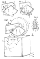
- the grinding wheel 2 can be seen, the axis 1 of which is arranged in an elongated component 3 consisting of two parallel arms.
- drives for the grinding wheel 2 are provided in the form of a belt pulley, not shown, via which a drive belt rotates, which mediates the drive of a motor located at the other end of the component 3.
- the grinding wheel 2 thus rotates about the grinding wheel axis 5, which runs parallel to the longitudinal axis 16 of the billet 14 to be machined.
- the stick 14 is displaced in the feed direction and rotated about its longitudinal axis 16 in the direction of the arrow 17 during this movement. This leads to the grinding wheel 2 machining the semifinished product surface 4, the penetration depth 6 of the machined semifinished product surface 4 being sufficient to prevent any cracks originally originating from the surface 4 from appearing.
- a segment 9 of a spiral forming the template is arranged on the grinding wheel bearing 10 on the side of the semi-finished surface 4 that has not yet been machined and can therefore be pivoted coaxially to the grinding wheel axis.
- a screw spindle 18 engages in the segment 9, for which a threaded block 12 is fastened to the component 3.
- the segment 9 can be set and determined in such a different way that the intended difference in height of the contact point 7 of the segment 9 with respect to the contact point of the grinding wheel 2 is maintained.
- the template 9 is on the opposite side.
- a further template 19 is provided on the side, in which the support point 13 lies on the already processed semi-finished surface 11 at the same height as for the grinding wheel 2. This results in an equally high support of the two-armed component 3 on both sides of the grinding wheel bearing 10 by means of the template 9 or 19 on the semifinished product surface 4 or 11.
- the further template 19 shown in Fig. 2 further allows that in an end position of the semi-finished product, when its feed is almost fully extended, there is also a support for the grinding wheel 2 when the opposite template is no longer on.
- the proposed height adjustability of the template can advantageously be controlled such that a change in distance occurs as a function of the angle of rotation, as a result of which the grinding wheel is raised in the corner area.
- a piston-cylinder unit 19, 20 is provided for the adjustability of the segment 9 designed as a stop.
- the cylinder is connected to a hydraulic control.
- the segment 9 is equipped with a roller 21.
- the circle segment is in this case of a somewhat smaller radius. It has an undercut groove track 29, indicated in the drawing, in which a screw nut, which cannot be seen in the drawing, is guided, so that the bearing bolt 30, which supports the roller 21, can be screwed in and tightened.
- the bearing roller 21 is fixed in a position as can be used for a limited height adjustment range of the segment 9.
- the segment 9 can be that of a circle and that of a spiral.
- the center of the circle 31 according to FIG. 1 lies at a short distance from the pivot bearing 32 of the segment passing through the grinding wheel axis 5, so that, based on the pivot point of the grinding wheel going through the grinding wheel axis 5 2, results in an eccentricity.
- the pivot bearing 32 can also be understood as the center of a spiral, of which the segment 9 represents a section. In this case, maintaining an eccentricity between the spiral center and the grinding wheel axis 5 is not indicated.
- the circumferential path of the segment 9 is largely identical in the drawing, as in the other case, so that a differentiated drawing has been dispensed with.
- the component 3 carrying the grinding wheel bearing is in turn pivotable in the fixed bearing block 33, so that the longitudinal center line 34 can assume different inclinations.
- the guide 35 has a scale for the purpose of setting a contact transmitter 23, which can be adjusted to a counter contact of the position transmitter 22.
- the highest and lowest position during the rotation of a stick can be read more easily on the position transmitter 22, so that, starting from the lowest position, the contact transmitter 23 can be adjusted to a certain altitude.
- the contactor is set to an altitude that is 2% above the lowest position.
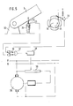
- a signal current leads directly from the contactor 23 to a switching switch 36 AND circuit 37.
- a signal current which flows via the switch 26 also leads to this switching switch 36.
- This switch 26 is under the influence of a switching cross 24 rotating with the stick 14, which moves a switch lever into its contact position during the rotation in the manner already described.
- the arrangement is expedient in such a way that there is a different switching state in the middle rotation region 28 by 20 ° than in the rotation region 27 of 35 ° which adjoins on both sides and extends to the corner.
- the two rotation regions 27, 28 mentioned are shown in FIG. 1.
- the AND circuit 37 allows either the contactor 23 or the switch 26 or both elements to be processed as an input signal by the switching switch 36 being set accordingly.
- the arithmetic amplifier 38 processes the received signal in such a way that, depending on the output of the arithmetic switch 38, the field controller 39 of a direct current bypass machine can be set to two different values such that the rotational speed of the drive motor 25 in the rotating range 27 is three times as large as in the rotating range 28 .
- FIG. 6 An optional arrangement for the semi-finished product to be driven at an uneven speed is shown in FIG. 6. Accordingly, there is an elliptical gear mechanism 40 which is connected via the gearwheel 41 to a drive motor rotating at the same speed. Together with the gearwheel 41, the toothed ellipse 42 rotates around its one focal point 43. It is in toothed engagement with the toothed ellipse 44 of the same size, which rotates around its one focal point 45. There is also a fixed connection between it and the driven gearwheel 46 . The latter drives the semi-finished gear 48, which has a fourfold circumference, so that four times the speed increases periodically when the latter rotates.
- the semi-finished product is in firm connection with the latter gear 48 in such a way that it is in the f turning regions 27 of the semi-finished product corners in relation to the rotating regions 28 ! r the middle of the semi-finished product comes to an increased speed 1 shows these areas.
- the extent of the non-uniformity can be selected by the choice of the eccentricity e and the large axis a of the two congruent elliptical gears, so that a correspondingly higher speed can be produced for the corner area than in the center area of the semi-finished product.
Landscapes
- Engineering & Computer Science (AREA)
- Mechanical Engineering (AREA)
- Grinding Of Cylindrical And Plane Surfaces (AREA)
- Grinding And Polishing Of Tertiary Curved Surfaces And Surfaces With Complex Shapes (AREA)
- Finish Polishing, Edge Sharpening, And Grinding By Specific Grinding Devices (AREA)
- Mechanical Treatment Of Semiconductor (AREA)
- Encapsulation Of And Coatings For Semiconductor Or Solid State Devices (AREA)
- Disintegrating Or Milling (AREA)
Priority Applications (1)
| Application Number | Priority Date | Filing Date | Title |
|---|---|---|---|
| AT86105987T ATE77783T1 (de) | 1985-05-14 | 1986-04-30 | Vorrichtung zum schleifen von halbzeug. |
Applications Claiming Priority (2)
| Application Number | Priority Date | Filing Date | Title |
|---|---|---|---|
| DE3517302 | 1985-05-14 | ||
| DE19853517302 DE3517302A1 (de) | 1985-05-14 | 1985-05-14 | Vorrichtung zum schleifen von halbzeug |
Publications (3)
| Publication Number | Publication Date |
|---|---|
| EP0201810A2 true EP0201810A2 (fr) | 1986-11-20 |
| EP0201810A3 EP0201810A3 (en) | 1989-08-23 |
| EP0201810B1 EP0201810B1 (fr) | 1992-07-01 |
Family
ID=6270673
Family Applications (1)
| Application Number | Title | Priority Date | Filing Date |
|---|---|---|---|
| EP86105987A Expired - Lifetime EP0201810B1 (fr) | 1985-05-14 | 1986-04-30 | Dispositif de meulage d'un produit semi-fini |
Country Status (4)
| Country | Link |
|---|---|
| US (1) | US4679355A (fr) |
| EP (1) | EP0201810B1 (fr) |
| AT (1) | ATE77783T1 (fr) |
| DE (2) | DE3517302A1 (fr) |
Families Citing this family (3)
| Publication number | Priority date | Publication date | Assignee | Title |
|---|---|---|---|---|
| JP6900019B2 (ja) * | 2016-05-25 | 2021-07-07 | 株式会社ナガセインテグレックス | 多面体ワークの研削方法 |
| US10058976B2 (en) | 2016-11-11 | 2018-08-28 | Att Technology, Ltd. | Hardbanding removal device and method |
| CN115502858A (zh) * | 2022-09-21 | 2022-12-23 | 马鞍山市鑫龙特钢有限公司 | 一种钢管胚料表面处理装置 |
Family Cites Families (16)
| Publication number | Priority date | Publication date | Assignee | Title |
|---|---|---|---|---|
| DE138615C (fr) * | ||||
| DE138618C (fr) * | ||||
| US2347639A (en) * | 1942-11-24 | 1944-04-25 | Driver Co Wilbur B | Bar-grinding apparatus |
| US2347503A (en) * | 1943-08-27 | 1944-04-25 | Driver Co Wilbur B | Bar-grinding apparatus |
| FR966400A (fr) * | 1948-05-13 | 1950-10-09 | Dispositif régulateur de pression applicable au meulage des lingots | |
| US2558943A (en) * | 1949-11-15 | 1951-07-03 | Driver Co Wilbur B | Bar grinding apparatus |
| GB831652A (en) * | 1956-08-10 | 1960-03-30 | Matisa Materiel Ind Sa | Grinding machine for rails, beams and like members |
| US2876598A (en) * | 1957-01-10 | 1959-03-10 | Allegheny Ludlum Steel | Grinding machine |
| US3040481A (en) * | 1960-09-16 | 1962-06-26 | Vlieg Howard Rawson De | Ice skate grinding machine |
| DE1272769B (de) * | 1964-11-07 | 1968-07-11 | Juenkerather Maschbau Gmbh | Pendelschleifmaschine zum allseitigen Schleifen oder Fehlerausschleifen von parallel zur Schleifscheibenachse reversierend laengsverschiebbaren Knueppeln oder dergleichen Halbzeug |
| US3823617A (en) * | 1972-04-28 | 1974-07-16 | Aqua Marine Mfg Ltd | Steering system |
| DE2336276C2 (de) * | 1972-07-21 | 1982-11-25 | Nolek System AB, Norsborg | Einrichtung zum Abschleifen von Graten an größeren Serien gleicher Werkstücke |
| HU167643B (fr) * | 1973-04-24 | 1975-11-28 | ||
| US3918209A (en) * | 1974-08-19 | 1975-11-11 | British Oxygen Co Ltd | Metal removal apparatus |
| FR2460182A1 (fr) * | 1979-06-29 | 1981-01-23 | Gendron Sa | Dispositif permettant d'usiner des cames avec precision, et avec une vitesse de coupe constante |
| DE3312898A1 (de) * | 1983-04-11 | 1984-10-11 | Vereinigte Glaswerke Gmbh, 5100 Aachen | Verfahren und vorrichtung zur positionssteuerung des werkzeugs einer kantenbearbeitungsmaschine fuer glasscheiben |
-
1985
- 1985-05-14 DE DE19853517302 patent/DE3517302A1/de active Granted
-
1986
- 1986-04-30 DE DE8686105987T patent/DE3685854D1/de not_active Expired - Lifetime
- 1986-04-30 AT AT86105987T patent/ATE77783T1/de not_active IP Right Cessation
- 1986-04-30 EP EP86105987A patent/EP0201810B1/fr not_active Expired - Lifetime
- 1986-05-13 US US06/862,653 patent/US4679355A/en not_active Expired - Fee Related
Also Published As
| Publication number | Publication date |
|---|---|
| DE3517302C2 (fr) | 1988-02-04 |
| ATE77783T1 (de) | 1992-07-15 |
| US4679355A (en) | 1987-07-14 |
| DE3685854D1 (de) | 1992-08-06 |
| EP0201810A3 (en) | 1989-08-23 |
| DE3517302A1 (de) | 1986-11-20 |
| EP0201810B1 (fr) | 1992-07-01 |
Similar Documents
| Publication | Publication Date | Title |
|---|---|---|
| DE1502416C2 (de) | Schleifvorrichtung für die Schleifscheibe einer Walzenschleifmaschine. Ausscheidung aus: 1427485 | |
| DE2612174B2 (de) | Schienenschleifmaschine für das Abschleifen von Unregelmäßigkeiten der Schienen-Fahrfläche | |
| DE3416664C2 (de) | Einrichtung zum Steuern der Schneidgeschwindigkeit des Sägeblattes einer Bandsägemaschine | |
| DE3049171C2 (fr) | ||
| DE2523225C2 (de) | Schleifmaschine, insbesondere zum Schleifen von Holzteilen | |
| EP0241892A2 (fr) | Ponceuse à bande | |
| DE2616401C2 (fr) | ||
| DE1777187B2 (de) | Spitzenlose schleifmaschine zum schleifen von langgestreckten stangen unterschiedlicher durchmesser im durchlaufverfahren | |
| DE19756503B4 (de) | Kehlmaschine | |
| DE2948719C2 (de) | Messerwalzen-Maschine zur Bearbeitung von Häuten und Fellen | |
| EP0201810B1 (fr) | Dispositif de meulage d'un produit semi-fini | |
| WO2010006572A1 (fr) | Granulateur de joncs à espace de coupe réglable | |
| DE2827917C2 (de) | Schleifmaschine zum Abrunden der Ecken von rechteckigen, plattenförmigen Werkstücken | |
| DE1652220C3 (de) | Verfahren zum spanabhebenden Bearbeiten eines Werkstücks | |
| DE2505985C3 (de) | Sägenschärfmaschine zum Schärfen von Zähnen unterschiedlicher Zahnspitzenhöhe | |
| EP0495354A1 (fr) | Aménagement pour traiter des pièces à usiner de tissu, en particulier en cuir ou similaires | |
| DE2807183B2 (de) | Maschine zum Abschneiden von Drahtenden an bestückten Leiterplatten | |
| DE3011786C2 (fr) | ||
| DE2452233A1 (de) | Konturenschleifmaschine | |
| DE3815639C2 (fr) | ||
| DE3048253A1 (de) | Geraet zum schaerfen der laufflaechenkanten von skiern | |
| EP1279453A2 (fr) | Dispositif de coupe rotatif ainsi que dispositif de réglage et tête de coupe pour un tel dispositif de coupe rotatif | |
| EP0510623B1 (fr) | Machine de réaffutage | |
| DE3815130A1 (de) | Vorrichtung zum zustellen von schleifscheiben einer bandmesserspaltmaschine | |
| DE1076469B (de) | Einrichtung an Verzahnungsschleifmaschinen zum Laengsballigschleifen von Gerad- und Schraegverzahnungen |
Legal Events
| Date | Code | Title | Description |
|---|---|---|---|
| PUAI | Public reference made under article 153(3) epc to a published international application that has entered the european phase |
Free format text: ORIGINAL CODE: 0009012 |
|
| AK | Designated contracting states |
Kind code of ref document: A2 Designated state(s): AT BE CH DE FR GB IT LI LU NL SE |
|
| PUAL | Search report despatched |
Free format text: ORIGINAL CODE: 0009013 |
|
| AK | Designated contracting states |
Kind code of ref document: A3 Designated state(s): AT BE CH DE FR GB IT LI LU NL SE |
|
| 17P | Request for examination filed |
Effective date: 19890923 |
|
| 17Q | First examination report despatched |
Effective date: 19910326 |
|
| GRAA | (expected) grant |
Free format text: ORIGINAL CODE: 0009210 |
|
| AK | Designated contracting states |
Kind code of ref document: B1 Designated state(s): AT BE CH DE FR GB IT LI LU NL SE |
|
| PG25 | Lapsed in a contracting state [announced via postgrant information from national office to epo] |
Ref country code: SE Effective date: 19920701 Ref country code: NL Effective date: 19920701 |
|
| REF | Corresponds to: |
Ref document number: 77783 Country of ref document: AT Date of ref document: 19920715 Kind code of ref document: T |
|
| REF | Corresponds to: |
Ref document number: 3685854 Country of ref document: DE Date of ref document: 19920806 |
|
| ITF | It: translation for a ep patent filed | ||
| GBT | Gb: translation of ep patent filed (gb section 77(6)(a)/1977) | ||
| ET | Fr: translation filed | ||
| NLV1 | Nl: lapsed or annulled due to failure to fulfill the requirements of art. 29p and 29m of the patents act | ||
| PG25 | Lapsed in a contracting state [announced via postgrant information from national office to epo] |
Ref country code: LU Free format text: LAPSE BECAUSE OF NON-PAYMENT OF DUE FEES Effective date: 19930430 Ref country code: LI Effective date: 19930430 Ref country code: GB Effective date: 19930430 Ref country code: CH Effective date: 19930430 Ref country code: BE Effective date: 19930430 Ref country code: AT Effective date: 19930430 |
|
| PLBE | No opposition filed within time limit |
Free format text: ORIGINAL CODE: 0009261 |
|
| STAA | Information on the status of an ep patent application or granted ep patent |
Free format text: STATUS: NO OPPOSITION FILED WITHIN TIME LIMIT |
|
| 26N | No opposition filed | ||
| BERE | Be: lapsed |
Owner name: EVERTZ EGON Effective date: 19930430 |
|
| PG25 | Lapsed in a contracting state [announced via postgrant information from national office to epo] |
Ref country code: FR Effective date: 19931229 |
|
| REG | Reference to a national code |
Ref country code: CH Ref legal event code: PL |
|
| PG25 | Lapsed in a contracting state [announced via postgrant information from national office to epo] |
Ref country code: DE Effective date: 19940101 |
|
| GBPC | Gb: european patent ceased through non-payment of renewal fee |
Effective date: 19930430 |
|
| REG | Reference to a national code |
Ref country code: FR Ref legal event code: ST |
|
| PG25 | Lapsed in a contracting state [announced via postgrant information from national office to epo] |
Ref country code: IT Free format text: LAPSE BECAUSE OF NON-PAYMENT OF DUE FEES;WARNING: LAPSES OF ITALIAN PATENTS WITH EFFECTIVE DATE BEFORE 2007 MAY HAVE OCCURRED AT ANY TIME BEFORE 2007. THE CORRECT EFFECTIVE DATE MAY BE DIFFERENT FROM THE ONE RECORDED. Effective date: 20050430 |