EP0201826B2 - Corps de bobine - Google Patents
Corps de bobine Download PDFInfo
- Publication number
- EP0201826B2 EP0201826B2 EP86106099A EP86106099A EP0201826B2 EP 0201826 B2 EP0201826 B2 EP 0201826B2 EP 86106099 A EP86106099 A EP 86106099A EP 86106099 A EP86106099 A EP 86106099A EP 0201826 B2 EP0201826 B2 EP 0201826B2
- Authority
- EP
- European Patent Office
- Prior art keywords
- winding carrier
- collar
- ring
- accordance
- winding
- Prior art date
- Legal status (The legal status is an assumption and is not a legal conclusion. Google has not performed a legal analysis and makes no representation as to the accuracy of the status listed.)
- Expired - Lifetime
Links
Images

Classifications
-
- D—TEXTILES; PAPER
- D06—TREATMENT OF TEXTILES OR THE LIKE; LAUNDERING; FLEXIBLE MATERIALS NOT OTHERWISE PROVIDED FOR
- D06B—TREATING TEXTILE MATERIALS USING LIQUIDS, GASES OR VAPOURS
- D06B23/00—Component parts, details, or accessories of apparatus or machines, specially adapted for the treating of textile materials, not restricted to a particular kind of apparatus, provided for in groups D06B1/00 - D06B21/00
- D06B23/04—Carriers or supports for textile materials to be treated
- D06B23/042—Perforated supports
-
- B—PERFORMING OPERATIONS; TRANSPORTING
- B65—CONVEYING; PACKING; STORING; HANDLING THIN OR FILAMENTARY MATERIAL
- B65H—HANDLING THIN OR FILAMENTARY MATERIAL, e.g. SHEETS, WEBS, CABLES
- B65H75/00—Storing webs, tapes, or filamentary material, e.g. on reels
- B65H75/02—Cores, formers, supports, or holders for coiled, wound, or folded material, e.g. reels, spindles, bobbins, cop tubes, cans, mandrels or chucks
- B65H75/18—Constructional details
- B65H75/28—Arrangements for positively securing ends of material
-
- B—PERFORMING OPERATIONS; TRANSPORTING
- B65—CONVEYING; PACKING; STORING; HANDLING THIN OR FILAMENTARY MATERIAL
- B65H—HANDLING THIN OR FILAMENTARY MATERIAL, e.g. SHEETS, WEBS, CABLES
- B65H2701/00—Handled material; Storage means
- B65H2701/30—Handled filamentary material
- B65H2701/31—Textiles threads or artificial strands of filaments
-
- B—PERFORMING OPERATIONS; TRANSPORTING
- B65—CONVEYING; PACKING; STORING; HANDLING THIN OR FILAMENTARY MATERIAL
- B65H—HANDLING THIN OR FILAMENTARY MATERIAL, e.g. SHEETS, WEBS, CABLES
- B65H2701/00—Handled material; Storage means
- B65H2701/50—Storage means for webs, tapes, or filamentary material
- B65H2701/53—Adaptations of cores or reels for special purposes
- B65H2701/534—Stackable or interlockable reels or parts of reels
Definitions
- the invention relates to a one-piece rigid winding support for receiving yarns and the like with a thread reserve area and with a substantially cylindrical, formed by cage-like support elements formed jacket surface, which has a closed end ring with a radially inner cover surface at one end and a closed end ring at its other end has an upper ring with an axially projecting collar, which at least in sections has smaller radial outer dimensions than the cover surface.
- a winding carrier is part of the prior art due to obvious prior use.
- a lower end ring which has a thread reserve groove on its radially outer surface.
- This end ring has a centering receptacle in which a centering projection of an axially adjacent winding carrier can engage. The interaction of the centering receptacle of the one and the centering shoulder of the adjacent winding carrier thus creates a sealing coupling between two winding carriers, which prevents the dye liquor from passing through in the region of the adjoining winding carriers.
- This known winding carrier which is advantageous for many applications, has the disadvantage that the thread reserve located in the thread reserve groove is covered with axial compression of the winding carriers located on superposed winding carriers and can therefore no longer be found or can only be found again in the subsequent processing .
- a winding carrier consisting of two sleeve parts
- DE-GM 85 14 349 which has a substantially cylindrical outer surface for receiving a yarn package.
- Both sleeve parts have an axial direction extending support elements which are connected to one another by ring elements. Only one of the sleeve parts has at its one end a circumferentially closed thrust ring, which has a thrust ring surface protruding radially outwards over the winding surface and a cover surface at its radially inner edge and a guide surface which is offset further radially inwards.
- axially projecting ring body At the outer end of the other sleeve part is an in Relative to the winding surface radially inwardly offset, axially projecting ring body is provided, the outer surface radius of which is equal to or slightly smaller than the radius of the guide surface of the thrust ring.
- the intermeshing ends of the sleeve parts are connected on the one hand to a locking ring which can be released by the action of pressure from the supporting elements and on the other hand are firmly connected to a support ring, the locking ring and support ring coming into contact with one another.
- the ring body of one winding carrier engages in the thrust ring of the axially adjacent winding carrier, the outer surface of the ring body cooperating with the guide surface of the thrust ring.
- the cover surface of the thrust ring covers a further part of the outer surface of the ring body. In this covered area of the ring body, a thread reserve can thus be accommodated, which is completely protected when such winding carriers are placed axially one into the other and is freely accessible after the winding carrier column has been dissolved into individual winding carriers.
- a winding carrier according to DE-GM 85 14 349 was obviously used in which the axial width of the federal government is greater than the width of the cover surface of the end ring.
- the object of the present invention is to design a winding support of the type mentioned at the outset in such a way that the thread reserve is protected at a defined point and also in the event of axial displacement of the associated winding, the transition of the thread between the winding and the thread reserve also being protected.
- This winding support is particularly suitable for assembling yarn packages in a columnar fashion on a dyeing sword or spear, in which case the dyeing liquor is then passed through the jacket wall of the winding support and the packages located thereon.
- the jacket with the jacket surface formed from it can be designed in many different embodiments.
- the winding carrier according to the invention can also be designed such that the end ring has a thrust ring surface projecting radially outward beyond the outer surface of the winding carrier. This ensures that a winding drum only acts on this end ring during winding and not on the elements of the outer surface forming the winding surface and the first layers of yarn wound thereon.
- the winding carrier according to the invention can also be designed such that the radially outer outer surface of the upper ring is adapted to the outer surface. This can result in particular advantages in terms of molding technology.
- the winding support according to the invention can also be designed such that the cover surface is delimited by a radially inwardly projecting shoulder. In this way, an exact dimension can be specified by which the collar of a winding carrier engages in the end ring of an axially adjacent winding carrier.
- the winding carrier according to the invention can also be designed such that the collar is delimited by a radially outwardly projecting ring shoulder. In this way too, the assignment of two adjacent winding carriers can be determined exactly.
- the winding support according to the invention can also be designed such that the cover surface is divided into an axially outer cover section and a guide section that is offset radially inward, and the radial outer dimensions of the collar are at least in its most axially projecting part the same or smaller than / than those of the guide section. In this way, a precise axial guidance of adjacent winding carriers "is ensured without thereby impairing the accommodation of the thread reserve in any way.
- the winding support according to the invention can also be designed such that the end ring is provided with ribs which extend evenly over the circumference from the cover surface and whose inner surfaces extend radially inwards onto an enveloping surface. These rib extensions can be used to guide nested winding supports and be beveled in a suitable manner to facilitate insertion. They can also be used to limit insertion.
- the winding support according to the invention can also be designed such that the upper ring is provided with projections which run in the axial direction over part of the collar and are distributed uniformly over the circumference, the outer surfaces of which extend into an enveloping surface, the radial dimensions of which are the same or smaller than / as those of the cover area.
- the thread reserve is on the bundle before the approaches.
- the winding carrier according to the invention can also be designed such that the axial extent of the projections of the upper ring is smaller than the axial extent of the rib projections of the end ring.
- the winding support according to the invention can be designed such that the number of the approaches of the upper ring is equal to that of the rib approaches of the end ring.
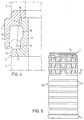
- 1-3 has an end ring 1 at one end and an upper ring 2 at its other end. Between these two rings 1, 2 there is a jacket 3 with a jacket surface 4 onto which the yarn is in the form of a Wikkels not shown can be wound up.
- the jacket 3 shown in broken lines in FIG. 1 is designed as a unit that is essentially rigid.
- the end ring 1 has a thrust ring surface 5 which is cylindrical in the exemplary embodiment and which is offset radially outward with respect to the outer surface 4.
- the inside of the end ring is essentially delimited by a cover surface 6, which is divided into a cover section 7 and a guide section 8.
- the cover section 7 lies on the axially outer end of the cover surface 6. This cover section 7 is followed radially inward by the guide section 8, to which an inwardly projecting shoulder 9 is connected.
- rib projections 10 are provided, which are distributed uniformly over the circumference.
- the rib extensions 10 increase in their radial extension in the direction of the shoulder 9. They have a rounded corner 11.
- the upper ring 2 at the other end of the winding support has an outer surface 12 which lies in the outer surface 4. After a shoulder 13, this outer surface 12 is followed by an axially projecting collar 14 with an outer diameter that is reduced compared to the outer surface 12.
- Axially extending shoulders 15 project beyond shoulder 13 and only extend over part of the width of collar 14.
- the outer diameter of the collar 14 is at most equal to that of the smallest envelope surface on which the radially inner edges of the rib extensions 10 extend.
- the collar 14 also has a thread reserve groove 16 with a further reduced outside diameter.
- the rib approaches 10 and the approaches 15 are evenly distributed over the circumference.
- the number of rib extensions 10 corresponds to that of the extensions 15.
- the axial length of the rib extensions 10 is greater than that of the extensions 15.
- the collar 14 of a winding carrier of the type described can be inserted into the end ring 1 of an axially adjacent winding carrier, the lugs 15 each lying between the rib lugs 10.
- the collar 14 extends into the guide section 8 of the end ring 1 and abuts the shoulder 9 there.
- a thread reserve can be accommodated in the thread reserve groove 16, from which a thread can be passed between the extensions 15 and the rib extensions 10 to the winding , which is located on the winding support.
- FIG. 4 shows the end ring 1 of an (upper) winding carrier and the upper ring 2 of a (lower) winding carrier.
- This figure in particular makes it clear that, in the stacked position, the collar 14 has its free end on the shoulder 9 of the end ring 1 bumps.
- the thread reserve groove 16 of the collar 14 is covered by the end ring 1, a gap remaining between the axially outer end of the end ring 1 on the one hand and the shoulder 13 or the outer surface 12 of the upper ring 2, through which a thread extends from the thread reserve groove 16 to a winding, not shown, can be performed, which is formed on the lateral surface 4 or is arranged there.
- FIG. 5 shows an embodiment of the winding support according to the invention which has a jacket 20 which has rings 21 which are connected to one another by struts 22 which are inclined to the axial direction.
- This jacket 20 results in an essentially rigid winding carrier with an end ring 1 and an upper ring 2 according to FIGS. 1-4.
- Thermoplastic material which can be used in the desired color, is particularly suitable for producing the winding support according to the invention in its various embodiments.
Landscapes
- Engineering & Computer Science (AREA)
- Textile Engineering (AREA)
- Storage Of Web-Like Or Filamentary Materials (AREA)
- Packaging Of Annular Or Rod-Shaped Articles, Wearing Apparel, Cassettes, Or The Like (AREA)
- Windings For Motors And Generators (AREA)
- Coils Or Transformers For Communication (AREA)
- Insulation, Fastening Of Motor, Generator Windings (AREA)
- Magnetic Resonance Imaging Apparatus (AREA)
- Winding Of Webs (AREA)
- Liquid Crystal Substances (AREA)
- Paper (AREA)
- Input Circuits Of Receivers And Coupling Of Receivers And Audio Equipment (AREA)
- Particle Accelerators (AREA)
- Supplying Of Containers To The Packaging Station (AREA)
- Vehicle Step Arrangements And Article Storage (AREA)
Claims (10)
- Corps de bobine rigide en une seule pièce destiné à la réception de fils et assimilés, comportant une zone de réserve de fil (16) et comportant une surface d'enveloppe (4) composée d'éléments de support essentiellement cylindriques reliés l'un à l'autre pour former une cage, présentant à une extrémité une bague terminale fermée (1) comportant une surface radiale de recouvrement (6) orientée vers l'intérieur, et à l'autre extrémité, une bague terminale fermée supérieure (2) munie d'un collet (14) débordant axialement qui possède des diamètres extérieurs inférieurs, au moins partiellement, à ceux de la surface de recouvrement (6). Le corps de bobine ici décrit est caractérisé en ce que le collet (14) est équipé d'une encoche (14) permettant la constitution d'une réserve de fil (16) et en ce que la largeur axiale du collet (14) de la bague supérieure (2) est supérieure à la largeur de la surface de recouvrement (6) de la bague terminale (1).
- Corps de bobine selon la revendication 1, caractérisé en ce que la bague terminale (1) présente une surface d'entraînement (5) qui dépasse radialement vers l'extérieur par rapport à la surface d'enveloppe (4) du corps de bobine.
- Corps de bobine selon l'une des revendications précédentes, caractérisé en ce que la surface extérieure (12) en direction radiale de la bague supérieure (2) est ajustée sur la surface de l'enveloppe (4).
- Corps de bobine selon l'une des revendications précédentes, caractérisé en ce que la surface de recouvrement (6) est délimitée par un épaulement (9) dépassant radialement vers l'intérieur.
- Corps de bobine selon l'une des revendications précédentes, caractérisé en ce que le collet (14) est délimité par un épaulement (13) dépassant radialement vers l'extérieur.
- Corps de bobine selon l'une des revendications précédentes, caractérisé en ce que la surface de recouvrement (6) se divise en un segment de recouvrement (7) orienté axialement vers l'extérieur, et un segment de guidage (8) décalé radialement vers l'intérieur par rapport à l'autre segment, et que les dimensions radiales extérieures du collet (14) sont, au moins à son extrémité axiale, inférieures ou égales à celles du segment de guidage (8).
- Corps de bobine selon l'une des revendications précédentes, caractérisé en ce que la bague terminale (1) est munie de rebords nervurés (10) qui sont uniformément répartis sur la circonférence et partent de la surface de recouvrement (6), et dont les surfaces intérieures se prolongent radialement vers l'intérieur sur une surface enveloppante.
- Corps de bobine selon l'une des revendications précédentes, caractérisé en ce que la bague terminale (2) est munie de rebords (15) disposés sur une partie du collet (14) et répartis uniformément sur la circonférence en direction axiale et dont les surfaces extérieures se prolongent pour former une surface enveloppante dont les dimensions radiales sont égales ou inférieures à celles de la surface de recouvrement (6).
- Corps de bobine selon la revendication 8, caractérisé en ce que l'extension axiale des rebords (15) de la bague supérieure (2) est inférieure à l'extension axiale des rebords nervurés (10) de la bague terminale (1).
- Corps de bobine selon la revendication 8 ou 9, caractérisé en ce que le nombre de rebords (15) de la bague supérieure (2) est égal à celui des rebords nervurés (10) de la bague terminale (1).
Priority Applications (1)
| Application Number | Priority Date | Filing Date | Title |
|---|---|---|---|
| AT86106099T ATE46128T1 (de) | 1985-05-10 | 1986-05-03 | Wickeltraeger. |
Applications Claiming Priority (2)
| Application Number | Priority Date | Filing Date | Title |
|---|---|---|---|
| DE8514349U DE8514349U1 (de) | 1985-05-10 | 1985-05-10 | Aus zwei Hülsenteilen bestehender Wickelträger |
| DE8514349U | 1985-05-10 |
Publications (4)
| Publication Number | Publication Date |
|---|---|
| EP0201826A2 EP0201826A2 (fr) | 1986-11-20 |
| EP0201826A3 EP0201826A3 (en) | 1987-08-05 |
| EP0201826B1 EP0201826B1 (fr) | 1989-09-06 |
| EP0201826B2 true EP0201826B2 (fr) | 1996-01-03 |
Family
ID=6781125
Family Applications (2)
| Application Number | Title | Priority Date | Filing Date |
|---|---|---|---|
| EP86105848A Expired EP0201794B1 (fr) | 1985-05-10 | 1986-04-28 | Corps de bobine formé de deux composants |
| EP86106099A Expired - Lifetime EP0201826B2 (fr) | 1985-05-10 | 1986-05-03 | Corps de bobine |
Family Applications Before (1)
| Application Number | Title | Priority Date | Filing Date |
|---|---|---|---|
| EP86105848A Expired EP0201794B1 (fr) | 1985-05-10 | 1986-04-28 | Corps de bobine formé de deux composants |
Country Status (6)
| Country | Link |
|---|---|
| US (1) | US4702433B1 (fr) |
| EP (2) | EP0201794B1 (fr) |
| AT (2) | ATE45332T1 (fr) |
| DE (3) | DE8514349U1 (fr) |
| ES (2) | ES294244Y (fr) |
| GR (2) | GR861213B (fr) |
Cited By (1)
| Publication number | Priority date | Publication date | Assignee | Title |
|---|---|---|---|---|
| DE102007001462A1 (de) | 2007-01-03 | 2008-07-10 | Manfred Hahm | Wickelträger |
Families Citing this family (16)
| Publication number | Priority date | Publication date | Assignee | Title |
|---|---|---|---|---|
| US4872621A (en) * | 1987-11-05 | 1989-10-10 | Crellin, Inc. | Spring dye tube |
| US4789111A (en) * | 1987-11-05 | 1988-12-06 | Crellin, Inc. | Dye tube |
| US4760976A (en) * | 1987-12-28 | 1988-08-02 | Burchette Jr Robert L | Transfer tail receiving structure for a yarn carrier |
| AT404720B (de) * | 1988-01-23 | 1999-02-25 | Becker Josef | Verfahren und färbehülse zum gleichmässigen verdichten von garn |
| IT1227805B (it) * | 1988-12-28 | 1991-05-07 | Tubettificio Europa Spa | Supporto tubolare per impacchi di filato, per tintoria |
| DE3909979A1 (de) * | 1989-03-25 | 1990-09-27 | Zimmermann Jos Gmbh & Co Kg | Wickeltraeger zur aufnahme von garnen sowie verfahren zu seiner anwendung |
| IT220991Z2 (it) * | 1990-08-23 | 1993-12-21 | Mariplast Spa | Tubetto per rocche di tintoria, con sagonature di estremita' atte a consentire nell'accoppiamento una circolazione di liquido fra le estremita' accoppiate, per agire sulle spire della riserva di filo |
| DE4202029A1 (de) * | 1992-01-25 | 1993-07-29 | Manfred Hahm | Wickeltraeger |
| DE4219844C2 (de) * | 1992-06-17 | 1997-02-06 | Zimmermann Jos Gmbh & Co Kg | In axialer Richtung zusammendrückbarer Wickelträger |
| US5577677A (en) * | 1995-02-28 | 1996-11-26 | Technimark, Inc. | Axially-compressible coil carrier |
| AU2936797A (en) | 1996-05-08 | 1997-11-26 | Technimark, Inc. | Apparatus for covering a textile dye tube |
| US5785801A (en) * | 1996-05-08 | 1998-07-28 | Technimark, Inc. | Apparatus for covering a textile dye tube |
| US6032890A (en) * | 1996-09-23 | 2000-03-07 | Sonoco Development, Inc. | Stacking stable yarn carrier for package dyeing |
| US5820049A (en) * | 1997-01-09 | 1998-10-13 | Technimark, Inc. | Rigid plastic dye tube |
| US6367724B1 (en) | 2000-06-09 | 2002-04-09 | Technimark, Inc. | Bi-directionally compressible dye tube |
| US7121500B2 (en) * | 2004-03-09 | 2006-10-17 | Sonoco Development, Inc. | Stackable winding core and method of making same |
Family Cites Families (17)
| Publication number | Priority date | Publication date | Assignee | Title |
|---|---|---|---|---|
| CH251098A (de) * | 1946-09-18 | 1947-10-15 | Scheuch Hermann | Spulrohr für die Aufnahme von Garn zum Färben desselben. |
| FR1416340A (fr) * | 1964-01-10 | 1965-11-05 | Grille support pour fil textile | |
| DE1635084C3 (de) * | 1966-11-10 | 1974-01-17 | Gerhard 5600 Wuppertalcronenberg Tigges | Wickelträger zur Behandlung von Fäden oder Garnen |
| DE7102230U (fr) * | 1971-01-21 | 1971-07-22 | Emil A | |
| ZA722971B (en) * | 1971-05-10 | 1973-02-28 | Jungbecker J | Axially telescopic thread or yard package carrier |
| US3759460A (en) * | 1971-07-01 | 1973-09-18 | Fyans Associates Inc | Collapsible yarn dye tube |
| GB1474673A (en) * | 1975-01-29 | 1977-05-25 | Gutermann Co Ag | Spool for thread |
| DE2730876C3 (de) * | 1977-07-08 | 1989-04-27 | Becker, Hubert, 5100 Aachen | Wickeltraeger aus stabfoermigen tragelementen |
| DE2845053C2 (de) * | 1978-10-16 | 1982-07-15 | Becker, Hubert | Wickelträger |
| JPS5655172Y2 (fr) * | 1979-04-27 | 1981-12-23 | ||
| US4331305A (en) * | 1980-09-25 | 1982-05-25 | Plastech Inc. | Rigid and compressible dye tubes |
| DE3036247A1 (de) * | 1980-09-26 | 1982-05-06 | Fa. Jos. Zimmermann, 5100 Aachen | Zylindrischer wickeltraeger zur aufnahme von faeden und garnen |
| US4379529A (en) * | 1981-02-19 | 1983-04-12 | Nielsen Hans B | Tube for yarn bobbin |
| DE8110872U1 (de) * | 1981-04-10 | 1981-09-10 | Fa. Jos. Zimmermann, 5100 Aachen | In axialer richtung zusammenschiebbarer wickeltraeger |
| DD203300A1 (de) * | 1981-11-30 | 1983-10-19 | Ernst Klein | Spulenhuelse zur erzielung einer leicht abarbeitbaren fadenreserve |
| FR2548698B1 (fr) * | 1983-07-04 | 1985-11-08 | Rhone Poulenc Fibres | Tube perfore pour enroulement de fil textile |
| DE8416028U1 (de) * | 1984-05-25 | 1984-08-30 | Fa. Jos. Zimmermann, 5100 Aachen | Wickeltraeger |
-
1985
- 1985-05-10 DE DE8514349U patent/DE8514349U1/de not_active Expired
-
1986
- 1986-04-28 DE DE8686105848T patent/DE3664898D1/de not_active Expired
- 1986-04-28 AT AT86105848T patent/ATE45332T1/de not_active IP Right Cessation
- 1986-04-28 EP EP86105848A patent/EP0201794B1/fr not_active Expired
- 1986-05-03 EP EP86106099A patent/EP0201826B2/fr not_active Expired - Lifetime
- 1986-05-03 DE DE8686106099T patent/DE3665439D1/de not_active Expired
- 1986-05-03 AT AT86106099T patent/ATE46128T1/de not_active IP Right Cessation
- 1986-05-08 ES ES1986294244U patent/ES294244Y/es not_active Expired
- 1986-05-09 US US06862601 patent/US4702433B1/en not_active Expired - Lifetime
- 1986-05-09 GR GR861213A patent/GR861213B/el unknown
- 1986-05-09 GR GR861212A patent/GR861212B/el unknown
- 1986-05-09 ES ES1986294248U patent/ES294248Y/es not_active Expired
Cited By (1)
| Publication number | Priority date | Publication date | Assignee | Title |
|---|---|---|---|---|
| DE102007001462A1 (de) | 2007-01-03 | 2008-07-10 | Manfred Hahm | Wickelträger |
Also Published As
| Publication number | Publication date |
|---|---|
| US4702433A (en) | 1987-10-27 |
| US4702433B1 (en) | 1997-07-22 |
| ES294244U (es) | 1986-10-16 |
| ATE46128T1 (de) | 1989-09-15 |
| EP0201794A2 (fr) | 1986-11-20 |
| EP0201826B1 (fr) | 1989-09-06 |
| ATE45332T1 (de) | 1989-08-15 |
| GR861213B (en) | 1986-09-10 |
| ES294244Y (es) | 1987-06-16 |
| DE3664898D1 (en) | 1989-09-14 |
| GR861212B (en) | 1986-09-10 |
| DE3665439D1 (en) | 1989-10-12 |
| DE8514349U1 (de) | 1985-07-18 |
| EP0201826A2 (fr) | 1986-11-20 |
| ES294248Y (es) | 1987-08-16 |
| ES294248U (es) | 1987-01-01 |
| EP0201794A3 (en) | 1987-08-26 |
| EP0201794B1 (fr) | 1989-08-09 |
| EP0201826A3 (en) | 1987-08-05 |
Similar Documents
| Publication | Publication Date | Title |
|---|---|---|
| EP0201826B1 (fr) | Corps de bobine | |
| DE2908342C2 (fr) | ||
| EP0678470B1 (fr) | Dispositif pour le stockage et le dévidage d'une tige flexible | |
| EP0628013A1 (fr) | Bobine pour la reception de matieres allongees a enrouler | |
| DE19840914C2 (de) | Kunststoffgebundener Ringmagnet | |
| DE2747423A1 (de) | Spulenkoerper fuer garn | |
| CH650572A5 (de) | Dichtungseinheit. | |
| EP3250171B1 (fr) | Dispositif pour transférer un liquide entre un réservoir et au moins un autre récipient d'utilisation | |
| DE2545346C2 (fr) | ||
| EP0048912B1 (fr) | Support d'enroulement pour recevoir des fils | |
| EP0018400B1 (fr) | Support de bobine avec elements porteurs paralleles a son axe | |
| EP0158324B1 (fr) | Support d'enroulements | |
| EP0208974B1 (fr) | Bobine | |
| EP0623091B1 (fr) | Bobine pour fil | |
| EP0389947A1 (fr) | Support d'enroulement de fils | |
| DE2243164C2 (de) | In axialer Richtung zusammenschiebbarer Wickelträger | |
| DE19917767C1 (de) | Wickelträger zur Aufnahme von Garn | |
| DE19652132C2 (de) | Mehrweghülse zum Aufspulen und Transportieren fadenförmiger oder bandförmiger Wirtschaftsgüter aus Natur- oder Kunststoffmaterial | |
| DE3628571C2 (fr) | ||
| EP0022877B1 (fr) | Support pour matériau bobiné à éléments porteurs s'étendant parallèlement à son axe | |
| DE69304017T2 (de) | Verbinderanordnung | |
| DE8110872U1 (de) | In axialer richtung zusammenschiebbarer wickeltraeger | |
| DE8612237U1 (de) | Wickelträger | |
| DE1660516C (de) | Garnspule | |
| DE8715906U1 (de) | Fadenfangring |
Legal Events
| Date | Code | Title | Description |
|---|---|---|---|
| PUAI | Public reference made under article 153(3) epc to a published international application that has entered the european phase |
Free format text: ORIGINAL CODE: 0009012 |
|
| AK | Designated contracting states |
Kind code of ref document: A2 Designated state(s): AT BE CH DE FR GB IT LI NL |
|
| PUAL | Search report despatched |
Free format text: ORIGINAL CODE: 0009013 |
|
| AK | Designated contracting states |
Kind code of ref document: A3 Designated state(s): AT BE CH DE FR GB IT LI NL |
|
| 17P | Request for examination filed |
Effective date: 19880107 |
|
| 17Q | First examination report despatched |
Effective date: 19890105 |
|
| GRAA | (expected) grant |
Free format text: ORIGINAL CODE: 0009210 |
|
| AK | Designated contracting states |
Kind code of ref document: B1 Designated state(s): AT BE CH DE FR GB IT LI NL |
|
| REF | Corresponds to: |
Ref document number: 46128 Country of ref document: AT Date of ref document: 19890915 Kind code of ref document: T |
|
| REF | Corresponds to: |
Ref document number: 3665439 Country of ref document: DE Date of ref document: 19891012 |
|
| GBT | Gb: translation of ep patent filed (gb section 77(6)(a)/1977) | ||
| ITF | It: translation for a ep patent filed | ||
| RAP2 | Party data changed (patent owner data changed or rights of a patent transferred) |
Owner name: JOS. ZIMMERMANN GMBH & CO. KG |
|
| REG | Reference to a national code |
Ref country code: CH Ref legal event code: PFA Free format text: JOS. ZIMMERMANN GMBH & CO. KG |
|
| ET | Fr: translation filed | ||
| BECN | Be: change of holder's name |
Effective date: 19890906 |
|
| NLT1 | Nl: modifications of names registered in virtue of documents presented to the patent office pursuant to art. 16 a, paragraph 1 |
Owner name: JOS. ZIMMERMANN GMBH & CO. KG TE AKEN, BONDSREPUBL |
|
| PLBI | Opposition filed |
Free format text: ORIGINAL CODE: 0009260 |
|
| 26 | Opposition filed |
Opponent name: H.N. ZAPF KG Effective date: 19900606 |
|
| NLR1 | Nl: opposition has been filed with the epo |
Opponent name: H.N. ZAPF KG. |
|
| ITTA | It: last paid annual fee | ||
| PUAH | Patent maintained in amended form |
Free format text: ORIGINAL CODE: 0009272 |
|
| STAA | Information on the status of an ep patent application or granted ep patent |
Free format text: STATUS: PATENT MAINTAINED AS AMENDED |
|
| 27A | Patent maintained in amended form |
Effective date: 19960103 |
|
| AK | Designated contracting states |
Kind code of ref document: B2 Designated state(s): AT BE CH DE FR GB IT LI NL |
|
| REG | Reference to a national code |
Ref country code: CH Ref legal event code: AEN Free format text: AUFRECHTERHALTUNG DES PATENTES IN GEAENDERTER FORM |
|
| NLR2 | Nl: decision of opposition | ||
| ITF | It: translation for a ep patent filed | ||
| GBTA | Gb: translation of amended ep patent filed (gb section 77(6)(b)/1977) |
Effective date: 19960403 |
|
| ET3 | Fr: translation filed ** decision concerning opposition | ||
| NLR3 | Nl: receipt of modified translations in the netherlands language after an opposition procedure | ||
| APAC | Appeal dossier modified |
Free format text: ORIGINAL CODE: EPIDOS NOAPO |
|
| APAC | Appeal dossier modified |
Free format text: ORIGINAL CODE: EPIDOS NOAPO |
|
| PGFP | Annual fee paid to national office [announced via postgrant information from national office to epo] |
Ref country code: FR Payment date: 20000517 Year of fee payment: 15 |
|
| PGFP | Annual fee paid to national office [announced via postgrant information from national office to epo] |
Ref country code: CH Payment date: 20000523 Year of fee payment: 15 Ref country code: BE Payment date: 20000523 Year of fee payment: 15 Ref country code: AT Payment date: 20000523 Year of fee payment: 15 |
|
| PGFP | Annual fee paid to national office [announced via postgrant information from national office to epo] |
Ref country code: NL Payment date: 20000524 Year of fee payment: 15 |
|
| PGFP | Annual fee paid to national office [announced via postgrant information from national office to epo] |
Ref country code: DE Payment date: 20000731 Year of fee payment: 15 |
|
| PGFP | Annual fee paid to national office [announced via postgrant information from national office to epo] |
Ref country code: GB Payment date: 20010417 Year of fee payment: 16 |
|
| PG25 | Lapsed in a contracting state [announced via postgrant information from national office to epo] |
Ref country code: AT Free format text: LAPSE BECAUSE OF NON-PAYMENT OF DUE FEES Effective date: 20010503 |
|
| PG25 | Lapsed in a contracting state [announced via postgrant information from national office to epo] |
Ref country code: BE Free format text: LAPSE BECAUSE OF NON-PAYMENT OF DUE FEES Effective date: 20010531 |
|
| PG25 | Lapsed in a contracting state [announced via postgrant information from national office to epo] |
Ref country code: LI Free format text: LAPSE BECAUSE OF NON-PAYMENT OF DUE FEES Effective date: 20010602 Ref country code: CH Free format text: LAPSE BECAUSE OF NON-PAYMENT OF DUE FEES Effective date: 20010602 |
|
| BERE | Be: lapsed |
Owner name: JOS. ZIMMERMANN G.M.B.H. & CO. K.G. Effective date: 20010531 |
|
| PG25 | Lapsed in a contracting state [announced via postgrant information from national office to epo] |
Ref country code: NL Free format text: LAPSE BECAUSE OF NON-PAYMENT OF DUE FEES Effective date: 20011201 |
|
| REG | Reference to a national code |
Ref country code: GB Ref legal event code: IF02 |
|
| REG | Reference to a national code |
Ref country code: CH Ref legal event code: PL |
|
| PG25 | Lapsed in a contracting state [announced via postgrant information from national office to epo] |
Ref country code: FR Free format text: LAPSE BECAUSE OF NON-PAYMENT OF DUE FEES Effective date: 20020131 |
|
| NLV4 | Nl: lapsed or anulled due to non-payment of the annual fee |
Effective date: 20011201 |
|
| PG25 | Lapsed in a contracting state [announced via postgrant information from national office to epo] |
Ref country code: DE Free format text: LAPSE BECAUSE OF NON-PAYMENT OF DUE FEES Effective date: 20020301 |
|
| PG25 | Lapsed in a contracting state [announced via postgrant information from national office to epo] |
Ref country code: GB Free format text: LAPSE BECAUSE OF NON-PAYMENT OF DUE FEES Effective date: 20020503 |
|
| GBPC | Gb: european patent ceased through non-payment of renewal fee |
Effective date: 20020503 |
|
| PG25 | Lapsed in a contracting state [announced via postgrant information from national office to epo] |
Ref country code: IT Free format text: LAPSE BECAUSE OF NON-PAYMENT OF DUE FEES;WARNING: LAPSES OF ITALIAN PATENTS WITH EFFECTIVE DATE BEFORE 2007 MAY HAVE OCCURRED AT ANY TIME BEFORE 2007. THE CORRECT EFFECTIVE DATE MAY BE DIFFERENT FROM THE ONE RECORDED. Effective date: 20050503 |
|
| APAH | Appeal reference modified |
Free format text: ORIGINAL CODE: EPIDOSCREFNO |