EP0201927A2 - Device for mixing and dispersing at least two media - Google Patents
Device for mixing and dispersing at least two media Download PDFInfo
- Publication number
- EP0201927A2 EP0201927A2 EP86106666A EP86106666A EP0201927A2 EP 0201927 A2 EP0201927 A2 EP 0201927A2 EP 86106666 A EP86106666 A EP 86106666A EP 86106666 A EP86106666 A EP 86106666A EP 0201927 A2 EP0201927 A2 EP 0201927A2
- Authority
- EP
- European Patent Office
- Prior art keywords
- rotor
- outlet
- stator
- media
- openings
- Prior art date
- Legal status (The legal status is an assumption and is not a legal conclusion. Google has not performed a legal analysis and makes no representation as to the accuracy of the status listed.)
- Granted
Links
- 238000002156 mixing Methods 0.000 title claims abstract description 14
- 230000007423 decrease Effects 0.000 claims description 5
- 239000006185 dispersion Substances 0.000 abstract description 26
- 239000000463 material Substances 0.000 description 15
- 239000000839 emulsion Substances 0.000 description 7
- 238000000034 method Methods 0.000 description 7
- 239000000843 powder Substances 0.000 description 6
- 230000000694 effects Effects 0.000 description 5
- 230000001133 acceleration Effects 0.000 description 4
- 238000004945 emulsification Methods 0.000 description 3
- 239000000126 substance Substances 0.000 description 3
- 230000001681 protective effect Effects 0.000 description 2
- IIDJRNMFWXDHID-UHFFFAOYSA-N Risedronic acid Chemical compound OP(=O)(O)C(P(O)(O)=O)(O)CC1=CC=CN=C1 IIDJRNMFWXDHID-UHFFFAOYSA-N 0.000 description 1
- 230000015572 biosynthetic process Effects 0.000 description 1
- 238000010276 construction Methods 0.000 description 1
- 238000000265 homogenisation Methods 0.000 description 1
- 230000001771 impaired effect Effects 0.000 description 1
- 238000004519 manufacturing process Methods 0.000 description 1
- 238000011089 mechanical engineering Methods 0.000 description 1
- 239000000203 mixture Substances 0.000 description 1
- 239000000479 mixture part Substances 0.000 description 1
- 238000003756 stirring Methods 0.000 description 1
- XLYOFNOQVPJJNP-UHFFFAOYSA-N water Substances O XLYOFNOQVPJJNP-UHFFFAOYSA-N 0.000 description 1
- 238000009736 wetting Methods 0.000 description 1
Images

Classifications
-
- B—PERFORMING OPERATIONS; TRANSPORTING
- B01—PHYSICAL OR CHEMICAL PROCESSES OR APPARATUS IN GENERAL
- B01F—MIXING, e.g. DISSOLVING, EMULSIFYING OR DISPERSING
- B01F27/00—Mixers with rotary stirring devices in fixed receptacles; Kneaders
- B01F27/80—Mixers with rotary stirring devices in fixed receptacles; Kneaders with stirrers rotating about a substantially vertical axis
- B01F27/81—Mixers with rotary stirring devices in fixed receptacles; Kneaders with stirrers rotating about a substantially vertical axis the stirrers having central axial inflow and substantially radial outflow
- B01F27/812—Mixers with rotary stirring devices in fixed receptacles; Kneaders with stirrers rotating about a substantially vertical axis the stirrers having central axial inflow and substantially radial outflow the stirrers co-operating with surrounding stators, or with intermeshing stators, e.g. comprising slits, orifices or screens
-
- B—PERFORMING OPERATIONS; TRANSPORTING
- B01—PHYSICAL OR CHEMICAL PROCESSES OR APPARATUS IN GENERAL
- B01F—MIXING, e.g. DISSOLVING, EMULSIFYING OR DISPERSING
- B01F33/00—Other mixers; Mixing plants; Combinations of mixers
- B01F33/86—Mixing heads comprising a driven stirrer
- B01F33/862—Mixing heads comprising a driven stirrer the stirrer being provided with a surrounding stator
Definitions
- the invention relates to a device according to the preamble of claim 1.
- a device of this type is described and shown in US-PS 44 37 765.
- the known device is a so-called jet mixer, in which the media are mixed with one another by rotating the rotor and due to the circulation, which is also based on the rotation of the rotor. Mixing is essentially achieved in the known embodiment. Dispersion is possible due to the presence of individual dispersing elements, but the dispersion of the material or the circulation speed is impaired by the dispersion because the dispersion takes place in the main stream. The dispersion effect is therefore imperfect.
- the invention has for its object to design a device of the type described above so that a partial stream of the at least premixed media can be fed to a safe dispersion.
- the main advantage of the embodiment according to the invention is that it enables simultaneous mixing and dispersion without mutual hindrance. These two processes are not integrated into one another within one stream, but they each take place in a partial stream, the dispersion stream being directed radially on account of the centrifugal force of the mixture parts set in rotation by the rotor.
- the radial acceleration of the at least premixed components is used for the more intensive operation of the device, namely dispersing, in which the media present in the partial flow are disrupted and finely distributed by supporting the radial acceleration.
- the proportion of dispersing and mixing work can also be determined by dimensioning the size of the outlet opening. This depends on the degree of dispersion and the type of media to be treated.
- the size can both be immutable for certain media can also be determined continuously or in stages (claim 5) for different media and / or different mixing or dispersing results.
- the size of the outlet opening for the mixed partial flow can take on relatively small amounts, the outlet opening can even be completely closed under certain circumstances, so that only the dispersed partial flow exits the stator exclusively through the openings for this partial flow.
- the configuration according to the invention is of particular importance for all processes which begin with the use of powder and require a lump-free and agglomerate-free disruption of the materials to be treated in the further treatment.
- Conventional dispersion systems have the disadvantage that, although they emulsify satisfactorily, they do not provide the circulating power for drawing in powder or other light materials. This means that especially in the critical phase, namely towards the end of the Benet process, with already increased viscosity floating powder lumps on the surface that can no longer be pulled down and dispersed.
- the entire process for powder wetting and subsequent homogenization of the powder or emulsification proceeds without problems and without difficult procedural measures. Compared to conventional systems, this means a considerable saving of time or an increase in quality and an increase in production reliability. This applies especially to emulsions, the stability of which can often not be predetermined.
- An advantageous further development of the invention consists in that the openings for the dispersed partial stream are formed by axially extending slots.
- This configuration enables a large number of slots lying in the direction of rotation of the rotor, as a result of which the dispersion capacity and the dispersion effect are increased.
- the latter is also verbes by the known design according to claim 4 through the shear edges on the opening edges and on the rotor blades, which enable a fine disintegration of the materials to be dispersed.
- the embodiment according to claim 6 is recommended, in which annular outlet cross sections can be realized.
- the formation of the adjustable closure member as a baffle plate according to claim 7 is recommended for structural reasons.
- the media are circulated by the influence of the rotating rotor, this influence being based on a set of the rotor blades (claim 9), on the centrifugal force or on both.
- An alternative measure for changing the size of the outlet opening is according to Claim 12 in changing the distance between the device and the bottom of the container in which the device is in operation with the media to be treated. As this distance decreases, the size of the outlet for the mixed partial flow also decreases. When the device rests on the underside on the bottom of the container, the outlet is completely closed, so that full flow dispersion takes place. With increasing distance from the bottom of the container, the proportion of dispersion can be reduced again. For the dependence of these measures, reference is made to the description of claim 5.
- a device for the measure described above can be of simple construction within the scope of the invention. It includes a container or other abutment, for. B. the container supporting base supportable frame which has a holding device for the device according to the invention, the holding device being axially adjustable to the device according to the invention and being fixable in the respective position on or in the frame.
- the device generally designated 1 in the figures, consists of a rotor, generally designated 2, which is mounted in a tubular stator 4 so as to be rotatable about an axis of rotation 3.
- the rotor 2 has a plurality of radially extending rotor blades 5 and is fastened to a vertically extending drive shaft 6, which is arranged within a protective tube 7 which carries the stator 4 and is connected to the latter by means of radially extending struts 8.
- the stator 4 consists of a vertically arranged tube 9 which is expanded in the shape of a trumpet on the upper side and with these edges 11 delimits an inlet, generally designated 12, for the materials to be treated.
- the struts 8 pass through this inlet 12 and connect the tube 9 to a sleeve 13 which is fastened on the protective tube 7.
- the tube 9 of the stator 4 is drawn in in the form of a radially extending annular wall 14 which encloses an outlet 15.
- the hollow cylindrical Wall section of the tube 9 and the annular wall 14 form a corner or inner shoulder of the stator 4, in which the rotor 2 is arranged.
- baffle plate 19 is axially adjustable in a manner not shown and can be locked in the respective position.
- the adjustability of the baffle plate 19 is shown by a double arrow 21.
- the diameter d of the rotor 2 is dimensioned so large that there is only a small gap s between the inner wall 22 of the tube 9 and the lateral surfaces 23 of the rotor 2. This gap s also extends between the side 24 of the rotor facing the outlet 15 and the inside 25 of the ring wall 14. Between the inside wall 22 and the inside 25 of the stator 4 and the lateral surface 23 and the side 24 of the rotor 2, a generally arises Scherfeld designated 26, the stator side shear edges 27 are formed by the inner edges 28 and its rotor-side shear edges 29 by the outer edges 31 and the side edges 32 of the rotor 2.
- the rotor blades 5 are set. This can be seen on the inclined side surfaces, which are designated by 33 in FIG. 2. Due to the setting of the rotor blades 5 of the rotor 2 rotating during operation in the direction of the arrow 34, the material to be treated, which consists of at least two different substances or media, is sucked into the stator 4 in the direction of the arrows 35 through the inlet 12. In the area of the rotor 2, the material is intimately mixed with one another, and it divides into an axial, generally 36 and a radial, generally 37 partial flow due to two feed forces. The partial flows are identified by radial and axial arrows.
- the axial partial flow 36 is a ring flow, and it is based on axial feed or acceleration forces which are caused by the setting of the rotor blades 5.
- the radial partial flow 37 spreads from the entire circumference of the stator 4 and is based on feed or acceleration forces which are caused by the centrifugal force of the material parts rotating with the rotor 2.
- Those located in the axial partial flow 36 Materials are mainly mixed intensively with one another, while the materials located in the radial partial flow 37 are subject to strong shear and impact effects in the shear field 26, as a result of which the desired dispersion and emulsification is effected.
- the proportion of the dispersion work in the radial partial flow 37 can be controlled by appropriate dimensioning of the distance a between the baffle plate 19 and the ring wall 14.
- the distance a determining the cross section of the outlet 15 should be selected to be relatively large. This is e.g. B. the case when light substances are to be incorporated, for. B. powders, which require a relatively large suction to pull them down from the surface of the material to be treated in the area of the stator.
- the baffle plate 19 differs from the one described above only in that the baffle plate 19 is not present.
- the device 1 for controlling the desired amount of dispersion or mixing work relative to the bottom 43 of the container 42 is axially adjusted.
- the proportion of the dispersion work is also determined by the size or length 1 of the slots 16. In the present exemplary embodiments, the length 1 corresponds to the width f of the rotor 2.
- the axial adjustment of the device 1 is expediently carried out by means of a holding device 45 which supports it and which can be displaced vertically (double arrow 46) in a guide 47 by means of an actuator (not shown).
- the actuator can e.g. B. be a pneumatically or hydraulically expandable actuating cylinder.
Landscapes
- Chemical & Material Sciences (AREA)
- Chemical Kinetics & Catalysis (AREA)
- Mixers Of The Rotary Stirring Type (AREA)
- Coating Apparatus (AREA)
Abstract
Die Erfindung bezieht sich auf eine Vorrichtung zum Mischen und Dispergieren mindestens zweier Medien, bestehend aus einem im wesentlichen rohrförmigen Stator (4) mit wenigstens einem im wesentlichen axialen Einlaß (12) und ei.nem im wesentlichen axialen Auslaß (15) für die Medien und einem zwischen dem Einlaß (12) und dem Auslaß (15) im Stator (4) zu diesem koaxialen Rotor (2) mit mehreren sich radial erstreckenden Rotorblättern (5). Damit ein Teilstrom der zumindest vorvermischten Medien einer sicheren Dispergierung zugeführt werden kann, weist der Stator (4) im Bereich des Rotors (2) radiale Öffnungen (16) auf.
Description
Die Erfindung bezieht sich auf eine Vorrichtung nach dem Oberbegriff des Anspruchs l.The invention relates to a device according to the preamble of
Eine Vorrichtung dieser Bauart ist in der US-PS 44 37 765 beschrieben und dargestellt. Bei der bekannten Vorrichtung handelt es sich um einen sogenannten Leitstrahlmischer, bei dem die Medien durch das Drehen des Rotors und aufgrund der Umwälzung, die ebenfalls auf der Rotation des Rotors beruht, miteinander vermischt werden. Bei der bekannten Ausgestaltung wird im wesentlichen ein Mischen erreicht. Ein Dispergieren ist zwar aufgrund des Vorhandenseins einzelner Dispergierelemente möglich, jedoch wird durch das Dispergieren die Umwälzung des Materials bzw. die Umwälzgeschwindigkeit beeinträchtigt, weil das Dispergieren im Hauptstrom erfolgt. Die Dispersionswirkung ist also unvollkommen.A device of this type is described and shown in US-PS 44 37 765. The known device is a so-called jet mixer, in which the media are mixed with one another by rotating the rotor and due to the circulation, which is also based on the rotation of the rotor. Mixing is essentially achieved in the known embodiment. Dispersion is possible due to the presence of individual dispersing elements, but the dispersion of the material or the circulation speed is impaired by the dispersion because the dispersion takes place in the main stream. The dispersion effect is therefore imperfect.
Der Erfindung liegt die Aufgabe zugrunde, eine Vorrichtung der eingangs bezeichneten Bauart so auszugestalten, daß ein Teilstrom der zumindest vorvermischten Medien einer sicheren Dispergierung zugeführt werden kann.The invention has for its object to design a device of the type described above so that a partial stream of the at least premixed media can be fed to a safe dispersion.
Diese Aufgabe wird durch die im Anspruch 1 enthaltenen Merkmale gelöst.This object is achieved by the features contained in
Der wesentliche Vorteil der erfindungsgemäßen Ausgestaltung besteht darin, daß sie ohne gegenseitige Behinderung ein gleichzeitiges Mischen und Dispergieren ermöglicht. Diese beiden Prozesse sind nicht innerhalb eines Stromes ineinander integriert, sondern sie erfolgen jeweils in einem Teilstrom, wobei der Dispergierstrom aufgrund der Fliehkraft der durch den Rotor in Rotation versetzten Gemischteile radial gerichtet ist. -Es wird somit die radiale Beschleunigung der zumindest vorvermischten Komponenten für den intensiveren Arbeitsgang der Vorrichtung, nämlich das Dispergieren, ausgenutzt, bei dem die im Teilstrom vorhandenen Medien durch Unterstützung der radialen Beschleunigung aufgeschlossen und fein verteilt werden.The main advantage of the embodiment according to the invention is that it enables simultaneous mixing and dispersion without mutual hindrance. These two processes are not integrated into one another within one stream, but they each take place in a partial stream, the dispersion stream being directed radially on account of the centrifugal force of the mixture parts set in rotation by the rotor. Thus, the radial acceleration of the at least premixed components is used for the more intensive operation of the device, namely dispersing, in which the media present in the partial flow are disrupted and finely distributed by supporting the radial acceleration.
D.h. im Betrieb der Vorrichtung verlassen zwei Gemischströme kontinuierlich die Vorrichtung, nämlich der dispergierte Teilstrom und der in herkömmlicher Weise vermischte Teilstrom. Auf diese Weise läßt sich durch die Bestimmung der Mischzeit der Anteil an Dispergier- und Mischarbeit entsprechend der Aufgabenstellung variieren und anpassen. Dies ist weder mit einer reinen Dispergiermaschine noch mit einem Strahlmischer möglich.I.e. During operation of the device, two mixture flows leave the device continuously, namely the dispersed partial flow and the partial flow mixed in a conventional manner. In this way, the proportion of dispersing and mixing work can be varied and adapted according to the task by determining the mixing time. This is neither possible with a pure dispersing machine nor with a jet mixer.
Der Anteil der Dispergier- und Mischarbeit läßt sich auch durch die Bemessung der Größe der Auslaßöffnung bestimmen. Diese richtet sich nach dem Dispergierungsgrad und nach der Art der zu behandelnden Medien. Die Größe kann sowohl unveränderlich für bestimmte Medien als auch kontinuierlich oder in Stufen variierbar (Anspruch 5) für unterschiedliche Medien und/oder unterschiedliche Mischungs- bzw. Dispergierergebnisse bestimmt werden.The proportion of dispersing and mixing work can also be determined by dimensioning the size of the outlet opening. This depends on the degree of dispersion and the type of media to be treated. The size can both be immutable for certain media can also be determined continuously or in stages (claim 5) for different media and / or different mixing or dispersing results.
Dabei kann im Rahmen der Erfindung die Größe der Auslaßöffnung für den gemischten Teilstrom verhältnismäßig kleine Beträge annehmen, die Auslaßöffnung kann unter Umständen sogar vollständig verschlossen werden, so daß nur der dispergierte Teilstrom ausschließlich durch die Öffnungen für diesen Teilstrom aus dem Stator austritt. Dies gilt insbesondere beim Vorhandensein von Öffnungen für den dispergierten Teilstrom, die in einem Eckbereich des Stators angeordnet sind (Anspruch 3) und sich deshalb teilweise radial und axial erstrecken.In the context of the invention, the size of the outlet opening for the mixed partial flow can take on relatively small amounts, the outlet opening can even be completely closed under certain circumstances, so that only the dispersed partial flow exits the stator exclusively through the openings for this partial flow. This applies in particular to the presence of openings for the dispersed partial stream, which are arranged in a corner region of the stator (claim 3) and therefore partially extend radially and axially.
Die erfindungsgemäße Ausgestaltung hat eine besondere Bedeutung für alle Prozesse, die mit der Benutzung von Pulver beginnen und in der Weiterbehandlung eine klumpen- und aglomeratfreie Aufschließung der zu behandelnden Materialien verlangen. Dasselbe gilt für Emulgierprozesse, bei denen zuerst eine grobe Emulsion gebildet wird und diese Emulsion durch die Untermischung der dispersen Phase und durch die Dauer der Bearbeitung so verfeinert wird, daß sie stabil bleibt. Herkömmliche Dispergiersysteme haben den Nachteil, daß sie zwar zufriedenstellend emulgieren, aber nicht die Umwälzleistung zum Einziehen von Pulver oder anderen leichten Materialien erbringen. Das bedeutet, daß insbesondere in der kritischen Phase, nämlich gegen Ende des Benetzungsprozesses, mit bereits erhöhter Viskosität Pulverklumpen an der Oberfläche schwimmen, die nicht mehr nach unten gezogen und dispergiert werden können. Hier muß dann sehr oft ein zusätzliches Rührelement eingebracht werden, damit der Prozess überhaupt zu Ende geführt werden kann. In einem solchen Fall, nämlich einer verhältnismäßig große Einzugswirkung auf das zu behandelnde Material, sind verhältnismäßig große axiale Auslaßöffnungen notwendig, z. B. im Bereich des gemischten Teilstroms oder im Bereich des dispergierten Teilstroms.The configuration according to the invention is of particular importance for all processes which begin with the use of powder and require a lump-free and agglomerate-free disruption of the materials to be treated in the further treatment. The same applies to emulsification processes in which a coarse emulsion is first formed and this emulsion is refined by the intermixing of the disperse phase and by the duration of the processing so that it remains stable. Conventional dispersion systems have the disadvantage that, although they emulsify satisfactorily, they do not provide the circulating power for drawing in powder or other light materials. This means that especially in the critical phase, namely towards the end of the Benet process, with already increased viscosity floating powder lumps on the surface that can no longer be pulled down and dispersed. An additional stirring element must then very often be introduced here so that the process can be completed at all. In such a case, namely a relatively large feed effect on the material to be treated, relatively large axial outlet openings are necessary, for. B. in the region of the mixed substream or in the region of the dispersed substream.
Bei der erfindungsgemäßen Ausgestaltung verläuft das ganze Verfahren zur Pulverbenetzung und anschließenden Homogenisierung des Pulvers bzw. der Emulgierung problemlos und ohne schwierige verfahrenstechnische Maßnahmen. Das bedeutet gegenüber herkömmlichen Systemen einen erheblichen Zeitgewinn bzw. eine Steigerung der Qualität und eine Steigerung der Produktionssicherheit. Dies gilt vor allem für Emulsionen, deren Stabilität oft nicht vorbestimmt werden kann.In the embodiment according to the invention, the entire process for powder wetting and subsequent homogenization of the powder or emulsification proceeds without problems and without difficult procedural measures. Compared to conventional systems, this means a considerable saving of time or an increase in quality and an increase in production reliability. This applies especially to emulsions, the stability of which can often not be predetermined.
Eine vorteilhafte Weiterbildung der Erfindung besteht gemäß Anspruch 2 darin, daß die Öffnungen für den dispergierten Teilstrom durch sich axial erstreckende Schlitze gebildet sind. Diese Ausgestaltung ermöglicht eine Vielzahl von in Drehrichtung des Rotors liegenden Schlitzen, wodurch die Dispergierungskapazität und der Dispergierungseffekt vergrößert werden. Letzterer wird auch durch die an sich bekannte Ausgestaltung gemäß Anspruch 4 verbessert, durch die Scherkanten an den Öffnungsrändern und an den Rotorblättern geschaffen werden, die eine feine Aufschließung der zu dispergierenden Materialien ermöglichen.An advantageous further development of the invention consists in that the openings for the dispersed partial stream are formed by axially extending slots. This configuration enables a large number of slots lying in the direction of rotation of the rotor, as a result of which the dispersion capacity and the dispersion effect are increased. The latter is also verbes by the known design according to claim 4 through the shear edges on the opening edges and on the rotor blades, which enable a fine disintegration of the materials to be dispersed.
In dem Fall, in dem der Auslaß für den gemischten Teilstrom veränderlich gestaltet werden soll, empfiehlt sich die Ausgestaltung nach Anspruch 6, bei der sich ringförmige Auslaßquerschnitte verwirklichen lassen. Dabei empfiehlt sich die Ausbildung des verstellbaren Verschlußgliedes als Stauscheibe gemäß Anspruch 7 aus baulichen Gründen.In the case in which the outlet for the mixed partial flow is to be made variable, the embodiment according to
Die Umwälzung der Medien erfolgt durch den Einfluß des rotierenden Rotors, wobei dieser Einfluß auf einer Schränkung der Rotorblätter (Anspruch 9), auf der Fliehkraft oder auf beiden beruhen kann.The media are circulated by the influence of the rotating rotor, this influence being based on a set of the rotor blades (claim 9), on the centrifugal force or on both.
Anstelle oder zusätzlich zu den Maßnahmen zur Beeinflussung des Anteils an Dispergier-und Mischarbeit (Größe der Auslaßöffnungen, Mischzeit) ist es auch möglich, die Schränkung im inneren und im äußeren Bereich des Rotors zu variieren. Es ist dabei jeweils nach Vorhandensein der zu behandelnden Materialien auch möglich, die Schränkungswinkel von innen nach außen zu vergrößern oder zu verkleinern (Ansprüche 9 bis 11). Welche Maßnahme zur Anwendung gelangt, bestimmt sich nach dem jeweiligen Anwendungsfall.Instead of or in addition to the measures for influencing the proportion of dispersion and mixing work (size of the outlet openings, mixing time), it is also possible to vary the setting in the inner and in the outer area of the rotor. Depending on the presence of the materials to be treated, it is also possible to increase or decrease the setting angle from the inside to the outside (claims 9 to 11). Which measure is used depends on the respective application.
Im Gegensatz zur bekannten Ausgestaltung, bei der eine Schließung des Auslasses im Stator eine Abnahme der Motorstromaufnahme bewirkt, wird bei der erfindungsgemäßen Ausgestaltung der Förderstrom umgelenkt, und die Motorstromaufnahme steigt aufgrund höheren Leistungsbedarfs an. Bei vollständig geschlossenem Auslaß für den gemischten Teilstrom, was im Rahmen der Erfindung wie schon erklärt möglich ist, ist die Motorstromaufnahme am größten, weil die größte Leistung zu erbringen ist.In contrast to the known design, in which the outlet is closed in the stator causes a decrease in the motor current consumption, the flow is deflected in the embodiment according to the invention, and the motor current consumption increases due to higher power requirements. When the outlet for the mixed partial flow is completely closed, which is possible within the scope of the invention as already explained, the motor current consumption is greatest because the greatest output has to be achieved.
Die vorbeschriebenen Vorteile der erfindungsgemäßen Ausgestaltung, wie die Möglichkeit der Dispergierung bei Wahrung einer verhältnismäßig großen Umwälzung der zu behandelnden Medien, gelten auch für Emulsionen, insbesondere Wasser--in-Öl-Emulsionen die zum Ende des Prozesses sehr viskos werden und eine starke Umwälzleistung des Systems erfordern. Diese Umwälzleistung besitzt ein reines Dispergiersystem nicht. Bei der erfindungsgemäßen Ausgestaltung ist es bei entsprechender Dimensionierung ohne weiteres möglich, Dispergiergeschwindigkeiten von 21 m/s zu erreichen. Dieser Wert gilt allgemein als Minimalwert zur Erstellung stabiler Emulsionen. Ein weiterer Vorteil der erfindungsgemäßen Ausgestaltung liegt daher auch in der einfachen Handhabung durch den Betreiber. Er kann durch Variierung der Arbeitszeit den Dispersionsgrad bzw. die Stabilität der Emulsion wesentlich beeinflussen, ohne dabei die maschinenbautechnischen Komponenten zu verändern.The above-described advantages of the embodiment according to the invention, such as the possibility of dispersion while maintaining a relatively large circulation of the media to be treated, also apply to emulsions, in particular water-in-oil emulsions, which become very viscous at the end of the process and have a strong circulation capacity System. A pure dispersing system does not have this circulation capacity. In the embodiment according to the invention, with appropriate dimensioning, it is readily possible to achieve dispersion speeds of 21 m / s. This value is generally regarded as the minimum value for creating stable emulsions. Another advantage of the configuration according to the invention is therefore the simple handling by the operator. By varying the working time, it can significantly influence the degree of dispersion or the stability of the emulsion without changing the mechanical engineering components.
Eine alternative Maßnahme zur Veränderung der Größe der Auslaßöffnung besteht gemäß Anspruch 12 darin, den Abstand zwischen der Vorrichtung und dem Boden des Behälters, in dem sich die Vorrichtung im Betrieb mit den zu behandelnden Medien befindet, zu verändern. Mit zunehmender Verringerung dieses Abstandes verringert sich auch die Größe des Auslasses für den gemischten Teilstrom. Wenn die Vorrichtung unterseitig auf dem Boden des Behälters aufliegt, ist der Auslaß vollständig geschlossen, so daß eine Vollstrom-Dispergierung erfolgt. Mit zunehmenden Abstand vom Boden des Behälters kann der Anteil der Dispergierung wieder verringert werden. Zur Abhängigkeit dieser Maßnahmen wird auf die Beschreibung zum Anspruch 5 verwiesen.An alternative measure for changing the size of the outlet opening is according to
Eine Vorrichtung zur vorbeschriebenen Maßnahme kann im Rahmen der Erfindung von einfacher Bauart sein. Sie umfaßt ein am Behälter oder an einem sonstigen Widerlager, z. B. dem den Behälter tragenden Grund abstützbares Gestell, das eine Haltevorrichtung für die erfindungsgemäße Vorrichtung aufweist, wobei die Haltevorrichtung axial zur erfindungsgemäßen Vorrichtung verstellbar und in der jeweiligen Stellung festlegbar am oder im Gestell angeordnet ist.A device for the measure described above can be of simple construction within the scope of the invention. It includes a container or other abutment, for. B. the container supporting base supportable frame which has a holding device for the device according to the invention, the holding device being axially adjustable to the device according to the invention and being fixable in the respective position on or in the frame.
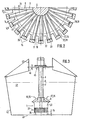
Nachfolgend werden bevorzugte Ausführungsbeispiele der Erfindung anhand einer vereinfachten Zeichnung näher beschrieben. Es zeigt:
- Fig. 1 eine erfindungsgemäß ausgestaltete Vorrichtung zum Mischen und Dispergieren mindestens zweier Medien im Vertikalschnitt als erstes Ausführungsbeispiel;
- Fig. 2 den Teilschnitt II-II in Fig. l;
- Fig. 3 ein zweites Ausführungsbeispiel der Vorrichtung mit einer Haltevorrichtung zur axialen Verstellung der Vorrichtung in einem Behälter.
- Fig. 1 shows an inventive device for mixing and dispersing at least two media in the Vertical section as the first embodiment;
- Fig. 2 shows the partial section II-II in Fig. 1;
- Fig. 3 shows a second embodiment of the device with a holding device for axial adjustment of the device in a container.
Die in den Figuren allgemein mit 1 bezeichnete Vorrichtung besteht aus einem allgemein mit 2 bezeichneten Rotor, der um eine Drehachse 3 drehbar in einem rohrförmigen Stator 4 gelagert ist. Der Rotor 2 weist eine Mehrzahl sich radial erstreckender Rotorblätter 5 auf und ist an einer senkrecht verlaufenden Antriebswelle 6 befestigt, die innerhalb eines Schutzrohres 7 angeordnet ist, das den Stator 4 trägt und mittels sich radial erstreckender Streben 8 mit diesem verbunden ist.The device, generally designated 1 in the figures, consists of a rotor, generally designated 2, which is mounted in a tubular stator 4 so as to be rotatable about an axis of rotation 3. The
Der Stator 4 besteht aus einem senkrecht angeordneten Rohr 9, das oberseitig trompetenförmig erweitert ist und mit diesen Rändern 11 einen allgemein mit 12 bezeichneten Einlaß für die zu behandelnden Materialien begrenzt. Die Streben 8 durchqueren diesen Einlaß 12 und verbinden das Rohr 9 mit einer Hülse 13, die auf dem Schutzrohr 7 befestigt ist.The stator 4 consists of a vertically arranged tube 9 which is expanded in the shape of a trumpet on the upper side and with these edges 11 delimits an inlet, generally designated 12, for the materials to be treated. The
Auf der dem Einlaß 12 abgewandten Seite ist das Rohr 9 des Stators 4 in Form einer sich radial erstreckenden Ringwand 14 eingezogen, die einen Auslaß 15 umschließt. Der hohlzylindrische Wandabschnitt des Rohres 9 und die Ringwand 14 bilden eine Ecke oder Innenschulter des Stators 4, in der der Rotor 2 angeordnet ist.On the side facing away from the
Im Bereich des Rotors 2 befinden sich im Rohr 9 radiale, sich längs der Drehachse 3 erstreckende Schlitze 16, die sich um einen mit b bezeichneten Betrag bis in die Ringwand 14 hinein erstrecken. Die Schlitze 16 weisen somit einen radialen und einen axialen Abschnitt 17, 18 auf.In the area of the
Unterhalb des Auslasses 15 ist eine Stauscheibe 19 in nicht dargestellter Weise axial verstellbar und in der jeweiligen Stellung feststellbar angeordnet. Die Verstellbarkeit der Stauscheibe 19 ist durch einen Doppelpfeil 21 dargestellt. Durch Verstellung der Stauscheibe 19 kann deren Abstand a von der Ringwand 14 eingestellt werden und zwar zwischen einem nicht dargestellten maximalen Wert und der Anlage an der Ringwand 14, in der kein Ringspalt mehr vorhanden ist, d.h. der Auslaß 15 geschlossen ist.Below the
Der Durchmesser d des Rotors 2 ist so groß bemessen, daß zwischen der Innenwand 22 des Rohres 9 und den Mantelflächen 23 des Rotors 2 nur ein kleiner Spalt s besteht. Dieser Spalt s erstreckt sich auch zwischen der dem Auslaß 15 zugewandten Seite 24 des Rotors und der Innenseite 25 der Ringwand 14. Zwischen der Innenwand 22 sowie der Innenseite 25 des Stators 4 und der Mantelfläche 23 sowie der Seite 24 des Rotors 2 entsteht somit ein allgemein mit 26 bezeichnetes Scherfeld, dessen statorseitige Scherkanten 27 durch die Innenkanten 28 und dessen rotorseitige Scherkanten 29 durch die Außenkanten 31 und die seitlichen Kanten 32 des Rotors 2 gebildet sind.The diameter d of the
Die Rotorblätter 5 sind geschränkt. Dies ist an den geneigten Seitenflächen erkennbar, die in Fig. 2 mit 33 bezeichnet sind. Aufgrund der Schränkung der Rotorblätter 5 des im Betrieb in Richtung des Pfeiles 34 drehenden Rotors 2 wird das aus wenigstens zwei unterschiedlichen Substanzen bzw. Medien bestehende und zu behandelnde Material in Richtung der Pfeile 35 durch den Einlaß 12 in den Stator 4 eingesaugt. Im Bereich des Rotors 2 wird das Material innig miteinander vermischt, und es teilt sich aufgrund von zwei Vorschubkräften in einen axialen, allgemein mit 36 und einen radialen, allgemein mit 37 bezeichneten Teilstrom. Die Teilströme sind durch radiale und axiale Pfeile gekennzeichnet.The
Der axiale Teilstrom 36 ist ein Ringstrom, und er beruht auf axialen Vorschub- bzw. Beschleunigungskräften, die aufgrund der Schränkung der Rotorblätter 5 hervorgerufen werden.The axial
Der radiale Teilstrom 37 breitet sich vom gesamten Umfang des Stators 4 aus und beruht auf Vorschub- bzw. Beschleunigungskräften, die durch die Fliehkraft der sich mit dem Rotor 2 drehenden Materialteile hervorgerufen werden.The radial
Die sich im axialen Teilstrom 36 befindlichen Materialien werden hauptsächlich intensiv miteinander vermischt, während die sich im radialen Teilstrom 37 befindlichen Materialien im Scherfeld 26 starken Scher- und Prallwirkungen unterliegen, wodurch die angestrebte Dispergierung und Emulgierung bewirkt wird. Der Anteil der Dispergierarbeit im radialen Teilstrom 37 kann durch eine entsprechende Bemessung des Abstands a zwischen der Stauscheibe 19 und der Ringwand 14 gesteuert werden. In Fällen, in denen eine verhältnismäßig große Umwälzleistung im Einlaßstrom (Pfeile 35) erwünscht ist, ist der den Querschnitt des Auslasses 15 bestimmende Abstand a verhältnismäßig groß zu wählen. Dies ist z. B. dann der Fall, wenn leichte Substanzen einzuarbeiten sind, z. B. Pulver, bei denen es einer verhältnismäßig großen Saugwirkung bedarf, um sie von der Oberfläche des zu behandelnden Materials nach unten in den Bereich des Stators ziehen zu können.Those located in the axial
In der vollständig geschlossenen Position der Stauscheibe 19 erfolgt eine Vollstrom-Dispergierung. Der gesamte Materialstrom tritt radial durch die Schlitze 16 aus, wobei er im Scherfeld 26 den vorgenannten Scher- und Prallwirkungen unterzogen wird. Da der Durchmesser der Stauscheibe 19 in etwa dem radialen Abstand c der axialen Schlitz-Abschnitte 18 voneinander entspricht, entsteht insbesondere in der vollständig geschlossenen Position der Stauscheibe 19 eine schräg nach unten gerichtete Komponente des radialen Teilstroms 37, die durch mit 38 bezeichneten Pfeilen verdeutlicht ist. Hierdurch wird die Verteilung des radialen dispergierten Teilstroms 37 bedeutend verbessert. Außerdem wird durch die radialen Abschnitte 17 der Schlitze 16 das Scherfeld 26 erheblich vergrößert, was im Sinne einer leistungsfähigen Aufschließung der zu dispergierenden Substanzen angestrebt wird.In the completely closed position of the
Das zweite Ausführungsbeispiel gemäß Fig. 3 unterscheidet sich vom vorbeschriebenen lediglich dadurch, daß die Stauscheibe 19 nicht vorhanden ist. Bei diesem Ausführungsbeispiel, bei dem die Vorrichtung 1 in einem aus zwei unterschiedlichen Medien, z. B. Wasser und Öl, bestehenden Behandlungsmaterial 41 eingetaucht ist, das sich in einem Behälter 42 befindet, wird die Vorrichtung 1 zur Steuerung des erwünschten Anteils an Dispergier- bzw. Mischarbeit gegenüber dem Boden 43 des Behälters 42 axial verstellt. Je größer der Abstand e zwischen der Unterseite der Vorrichtung 1 und dem Boden 43 eingestellt wird, desto geringer ist der radiale Teilstrom 37 bzw. der Anteil der Dispergierarbeit. Oberhalb eines bestimmten Abstandes e ändern sich die Anteile der Dispergier- und Mischarbeit jedoch nicht mehr. Der Anteil der Dispergierarbeit wird auch durch die Größe bzw. Länge 1 der Schlitze 16 bestimmt. Bei den vorliegenden Ausführungsbeispielen entspricht die Länge 1 der Breite f des Rotors 2.3 differs from the one described above only in that the
Wird die Vorrichtung 1 vollends gegen den Boden 43 geschoben, so daß der Abstand e gleich Null ist, dann ist der Auslaß 15 vollends geschlossen und es erfolgt eine Vollstrom-Dispergierung wie beim ersten Ausführungsbeispiel, wenn die Stauscheibe 19 den Auslaß 15 vollständig verschließt.If the
Das axiale Verstellen der Vorrichtung 1 erfolgt zweckmäßig mittels einer sie tragenden Haltevorrichtung 45, die durch ein nicht dargestelltes Stellglied vertikal (Doppelpfeil 46) in einer Führung 47 verschiebbar ist. Das Stellglied kann z. B. ein pneumatisch oder hydraulisch baufschlagbarer Stellzylinder sein.The axial adjustment of the
Claims (12)
Priority Applications (1)
| Application Number | Priority Date | Filing Date | Title |
|---|---|---|---|
| AT86106666T ATE82873T1 (en) | 1985-05-15 | 1986-05-15 | DEVICE FOR MIXING AND DISPERSING AT LEAST TWO MEDIA. |
Applications Claiming Priority (2)
| Application Number | Priority Date | Filing Date | Title |
|---|---|---|---|
| DE3517655 | 1985-05-15 | ||
| DE19853517655 DE3517655A1 (en) | 1985-05-15 | 1985-05-15 | DEVICE FOR MIXING AND DISPERSING AT LEAST TWO MEDIA |
Publications (3)
| Publication Number | Publication Date |
|---|---|
| EP0201927A2 true EP0201927A2 (en) | 1986-11-20 |
| EP0201927A3 EP0201927A3 (en) | 1988-05-18 |
| EP0201927B1 EP0201927B1 (en) | 1992-12-02 |
Family
ID=6270889
Family Applications (1)
| Application Number | Title | Priority Date | Filing Date |
|---|---|---|---|
| EP86106666A Expired - Lifetime EP0201927B1 (en) | 1985-05-15 | 1986-05-15 | Device for mixing and dispersing at least two media |
Country Status (4)
| Country | Link |
|---|---|
| US (1) | US4738543A (en) |
| EP (1) | EP0201927B1 (en) |
| AT (1) | ATE82873T1 (en) |
| DE (2) | DE3517655A1 (en) |
Cited By (3)
| Publication number | Priority date | Publication date | Assignee | Title |
|---|---|---|---|---|
| RU2162733C1 (en) * | 1999-06-15 | 2001-02-10 | Тамбовский государственный технический университет | Polymerization reactor |
| WO2013064663A1 (en) * | 2011-11-02 | 2013-05-10 | Fresenius Kabi Deutschland Gmbh | Device and method for preparing a fluid composition for complete or supplemental enteral nutrition |
| EP2939734A4 (en) * | 2012-12-25 | 2016-08-24 | M Tech Co Ltd | MIXING DEVICE AND METHOD |
Families Citing this family (6)
| Publication number | Priority date | Publication date | Assignee | Title |
|---|---|---|---|---|
| WO1990014880A1 (en) * | 1989-05-03 | 1990-12-13 | Ullrich, Manfred | Mixing device for fluids |
| DE4118870A1 (en) * | 1991-06-07 | 1992-12-17 | Ystral Gmbh Maschinenbau Und P | DEVICE FOR WETING AND DISPERSING POWDERS IN LIQUIDS |
| US6863431B2 (en) * | 1992-03-30 | 2005-03-08 | Omni International, Inc. | Disruptor device which eliminates cross contamination |
| WO2017022816A1 (en) | 2015-08-06 | 2017-02-09 | 株式会社明治 | Atomization device and method for manufacturing product with fluidity using said device |
| DE102016103968B4 (en) | 2016-03-04 | 2019-01-17 | Alexander Westphal | Stirrer, in particular jet mixer and stirring device comprising a stirrer |
| KR102666286B1 (en) * | 2019-04-15 | 2024-05-16 | 엠. 테크닉 가부시키가이샤 | agitator |
Family Cites Families (10)
| Publication number | Priority date | Publication date | Assignee | Title |
|---|---|---|---|---|
| US2875897A (en) * | 1953-06-22 | 1959-03-03 | Booth Lionel Earl | Flotation machine |
| US2985389A (en) * | 1955-09-02 | 1961-05-23 | Willems Peter | Apparatus for physical and/or chemical treatment of materials |
| DE1219447B (en) * | 1963-11-22 | 1966-06-23 | Karg G M B H Dr | Mixing head for homogenizing u. Like. From media of liquid to highly viscous consistency |
| US3724765A (en) * | 1971-09-03 | 1973-04-03 | Beckman Instruments Inc | Tablet disruptor device |
| DE2310321B1 (en) * | 1973-03-01 | 1974-01-31 | Int Laboratoriums App Gmbh | EMULSIFYING AND DISPERSING DEVICE WITH ROTATING CONCENTRIC TOOL EDGE |
| GB1518144A (en) * | 1975-07-04 | 1978-07-19 | Pilkington Brothers Ltd | Glass fibre reinforced cement composite materials |
| DE2702183A1 (en) * | 1977-01-20 | 1978-07-27 | Ystral Gmbh Maschinenbau Und P | Serially connected axial mixer and radial disperser - forming unit for prodn. of emulsions and suspensions |
| US4437765A (en) * | 1982-03-05 | 1984-03-20 | Ystral Gmbh | Dispersion turbine |
| DE3220092A1 (en) * | 1982-05-28 | 1983-12-01 | Janke & Kunkel GmbH & Co KG Ika - Werk, 7813 Staufen | DISPERSING DEVICE |
| GB2165462B (en) * | 1984-10-10 | 1988-02-03 | Unishear Mixers Ltd | Mixing apparatus stator device |
-
1985
- 1985-05-15 DE DE19853517655 patent/DE3517655A1/en active Granted
-
1986
- 1986-05-15 US US06/863,702 patent/US4738543A/en not_active Expired - Lifetime
- 1986-05-15 EP EP86106666A patent/EP0201927B1/en not_active Expired - Lifetime
- 1986-05-15 AT AT86106666T patent/ATE82873T1/en active
- 1986-05-15 DE DE8686106666T patent/DE3687183D1/en not_active Expired - Lifetime
Cited By (5)
| Publication number | Priority date | Publication date | Assignee | Title |
|---|---|---|---|---|
| RU2162733C1 (en) * | 1999-06-15 | 2001-02-10 | Тамбовский государственный технический университет | Polymerization reactor |
| WO2013064663A1 (en) * | 2011-11-02 | 2013-05-10 | Fresenius Kabi Deutschland Gmbh | Device and method for preparing a fluid composition for complete or supplemental enteral nutrition |
| EP2939734A4 (en) * | 2012-12-25 | 2016-08-24 | M Tech Co Ltd | MIXING DEVICE AND METHOD |
| JPWO2014102906A1 (en) * | 2012-12-25 | 2017-01-12 | エム・テクニック株式会社 | Agitation processing apparatus and processing method |
| US9925503B2 (en) | 2012-12-25 | 2018-03-27 | M. Technique Co., Ltd. | Stirring-processing apparatus and processing method |
Also Published As
| Publication number | Publication date |
|---|---|
| DE3517655A1 (en) | 1986-11-20 |
| EP0201927B1 (en) | 1992-12-02 |
| US4738543A (en) | 1988-04-19 |
| DE3517655C2 (en) | 1987-07-16 |
| DE3687183D1 (en) | 1993-01-14 |
| ATE82873T1 (en) | 1992-12-15 |
| EP0201927A3 (en) | 1988-05-18 |
Similar Documents
| Publication | Publication Date | Title |
|---|---|---|
| DE2655901C2 (en) | ||
| DE69124571T2 (en) | Emulsification process and device | |
| DE10204921C1 (en) | Dispersing apparatus | |
| DE9106768U1 (en) | Gassing stirrer | |
| DE3243671C2 (en) | ||
| DE1457270B2 (en) | LIQUID MIXERS | |
| EP0570335A1 (en) | Device and process for mixing a pulverulent solid component to a liquid material | |
| EP0201927B1 (en) | Device for mixing and dispersing at least two media | |
| DE1782775B2 (en) | Rotary air separator. Eliminated from: 1507683 | |
| WO1992021436A1 (en) | Device for dispersing, suspending or emulsifying gasses, liquids and/or free-flowing solid substances | |
| DE3342304A1 (en) | HOMOGENIZING MACHINE | |
| DE1557184A1 (en) | Device for continuous mixing, homogenizing and aerating of pasty masses, especially chocolate masses | |
| DE3738223C2 (en) | Apparatus for intensive mixing of liquids or a liquid-solid mixture, for treating water, aqueous solutions or other liquids and melts | |
| DE6910964U (en) | MIXING DEVICE | |
| DE2236200C3 (en) | GieBeref mixing machine for mixing a granular or powdery molding material with a liquid binder | |
| DE2740789C2 (en) | Device for the continuous mechanical mixing of two components | |
| DE69309932T2 (en) | DEVICE FOR ADMINISTERING TREATMENT AGENTS TO A SULFENSION | |
| EP3334519B1 (en) | Device and method for dispersing at least one substance in a fluid | |
| EP0475015B1 (en) | Method and apparatus for continuously grinding and dispersing solids in fluids | |
| DE3002429C2 (en) | ||
| DE3016374C2 (en) | Dispersing turbine | |
| DE3018729A1 (en) | Liq. and powder simultaneously fed without clogging - or agglomeration into processing machines such as extruders | |
| DE1457270C (en) | Liquid mixer | |
| CH364492A (en) | Emulsifying device | |
| AT288586B (en) | Extrusion press with turntable for the treatment of high polymers |
Legal Events
| Date | Code | Title | Description |
|---|---|---|---|
| PUAI | Public reference made under article 153(3) epc to a published international application that has entered the european phase |
Free format text: ORIGINAL CODE: 0009012 |
|
| AK | Designated contracting states |
Kind code of ref document: A2 Designated state(s): AT BE CH DE FR GB IT LI LU NL SE |
|
| PUAL | Search report despatched |
Free format text: ORIGINAL CODE: 0009013 |
|
| AK | Designated contracting states |
Kind code of ref document: A3 Designated state(s): AT BE CH DE FR GB IT LI LU NL SE |
|
| 17P | Request for examination filed |
Effective date: 19880701 |
|
| 17Q | First examination report despatched |
Effective date: 19891027 |
|
| GRAA | (expected) grant |
Free format text: ORIGINAL CODE: 0009210 |
|
| AK | Designated contracting states |
Kind code of ref document: B1 Designated state(s): AT BE CH DE FR GB IT LI LU NL SE |
|
| PG25 | Lapsed in a contracting state [announced via postgrant information from national office to epo] |
Ref country code: IT Free format text: LAPSE BECAUSE OF FAILURE TO SUBMIT A TRANSLATION OF THE DESCRIPTION OR TO PAY THE FEE WITHIN THE PRE;WARNING: LAPSES OF ITALIAN PATENTS WITH EFFECTIVE DATE BEFORE 2007 MAY HAVE OCCURRED AT ANY TIME BEFORE 2007. THE CORRECT EFFECTIVE DATE MAY BE DIFFERENT FROM THE ONE RECORDED.SCRIBED TIME-LIMIT Effective date: 19921202 Ref country code: BE Effective date: 19921202 Ref country code: SE Effective date: 19921202 Ref country code: NL Effective date: 19921202 |
|
| REF | Corresponds to: |
Ref document number: 82873 Country of ref document: AT Date of ref document: 19921215 Kind code of ref document: T |
|
| GBT | Gb: translation of ep patent filed (gb section 77(6)(a)/1977) |
Effective date: 19921201 |
|
| REF | Corresponds to: |
Ref document number: 3687183 Country of ref document: DE Date of ref document: 19930114 |
|
| ET | Fr: translation filed | ||
| PG25 | Lapsed in a contracting state [announced via postgrant information from national office to epo] |
Ref country code: AT Effective date: 19930515 |
|
| NLV1 | Nl: lapsed or annulled due to failure to fulfill the requirements of art. 29p and 29m of the patents act | ||
| PG25 | Lapsed in a contracting state [announced via postgrant information from national office to epo] |
Ref country code: LU Free format text: LAPSE BECAUSE OF NON-PAYMENT OF DUE FEES Effective date: 19930531 |
|
| PLBE | No opposition filed within time limit |
Free format text: ORIGINAL CODE: 0009261 |
|
| STAA | Information on the status of an ep patent application or granted ep patent |
Free format text: STATUS: NO OPPOSITION FILED WITHIN TIME LIMIT |
|
| 26N | No opposition filed | ||
| REG | Reference to a national code |
Ref country code: GB Ref legal event code: IF02 |
|
| PGFP | Annual fee paid to national office [announced via postgrant information from national office to epo] |
Ref country code: GB Payment date: 20050503 Year of fee payment: 20 |
|
| PGFP | Annual fee paid to national office [announced via postgrant information from national office to epo] |
Ref country code: FR Payment date: 20050519 Year of fee payment: 20 |
|
| PGFP | Annual fee paid to national office [announced via postgrant information from national office to epo] |
Ref country code: CH Payment date: 20050524 Year of fee payment: 20 |
|
| REG | Reference to a national code |
Ref country code: GB Ref legal event code: PE20 |
|
| PGFP | Annual fee paid to national office [announced via postgrant information from national office to epo] |
Ref country code: DE Payment date: 20050729 Year of fee payment: 20 |
|
| PG25 | Lapsed in a contracting state [announced via postgrant information from national office to epo] |
Ref country code: GB Free format text: LAPSE BECAUSE OF EXPIRATION OF PROTECTION Effective date: 20060514 |
|
| REG | Reference to a national code |
Ref country code: CH Ref legal event code: PL |