EP0201927A2 - Dispositif pour mélanger et disperser au moins deux milieux - Google Patents
Dispositif pour mélanger et disperser au moins deux milieux Download PDFInfo
- Publication number
- EP0201927A2 EP0201927A2 EP86106666A EP86106666A EP0201927A2 EP 0201927 A2 EP0201927 A2 EP 0201927A2 EP 86106666 A EP86106666 A EP 86106666A EP 86106666 A EP86106666 A EP 86106666A EP 0201927 A2 EP0201927 A2 EP 0201927A2
- Authority
- EP
- European Patent Office
- Prior art keywords
- rotor
- outlet
- stator
- media
- openings
- Prior art date
- Legal status (The legal status is an assumption and is not a legal conclusion. Google has not performed a legal analysis and makes no representation as to the accuracy of the status listed.)
- Granted
Links
- 238000002156 mixing Methods 0.000 title claims abstract description 14
- 230000007423 decrease Effects 0.000 claims description 5
- 239000006185 dispersion Substances 0.000 abstract description 26
- 239000000463 material Substances 0.000 description 15
- 239000000839 emulsion Substances 0.000 description 7
- 238000000034 method Methods 0.000 description 7
- 239000000843 powder Substances 0.000 description 6
- 230000000694 effects Effects 0.000 description 5
- 230000001133 acceleration Effects 0.000 description 4
- 238000004945 emulsification Methods 0.000 description 3
- 239000000126 substance Substances 0.000 description 3
- 230000001681 protective effect Effects 0.000 description 2
- IIDJRNMFWXDHID-UHFFFAOYSA-N Risedronic acid Chemical compound OP(=O)(O)C(P(O)(O)=O)(O)CC1=CC=CN=C1 IIDJRNMFWXDHID-UHFFFAOYSA-N 0.000 description 1
- 230000015572 biosynthetic process Effects 0.000 description 1
- 238000010276 construction Methods 0.000 description 1
- 238000000265 homogenisation Methods 0.000 description 1
- 230000001771 impaired effect Effects 0.000 description 1
- 238000004519 manufacturing process Methods 0.000 description 1
- 238000011089 mechanical engineering Methods 0.000 description 1
- 239000000203 mixture Substances 0.000 description 1
- 239000000479 mixture part Substances 0.000 description 1
- 238000003756 stirring Methods 0.000 description 1
- XLYOFNOQVPJJNP-UHFFFAOYSA-N water Substances O XLYOFNOQVPJJNP-UHFFFAOYSA-N 0.000 description 1
- 238000009736 wetting Methods 0.000 description 1
Images

Classifications
-
- B—PERFORMING OPERATIONS; TRANSPORTING
- B01—PHYSICAL OR CHEMICAL PROCESSES OR APPARATUS IN GENERAL
- B01F—MIXING, e.g. DISSOLVING, EMULSIFYING OR DISPERSING
- B01F27/00—Mixers with rotary stirring devices in fixed receptacles; Kneaders
- B01F27/80—Mixers with rotary stirring devices in fixed receptacles; Kneaders with stirrers rotating about a substantially vertical axis
- B01F27/81—Mixers with rotary stirring devices in fixed receptacles; Kneaders with stirrers rotating about a substantially vertical axis the stirrers having central axial inflow and substantially radial outflow
- B01F27/812—Mixers with rotary stirring devices in fixed receptacles; Kneaders with stirrers rotating about a substantially vertical axis the stirrers having central axial inflow and substantially radial outflow the stirrers co-operating with surrounding stators, or with intermeshing stators, e.g. comprising slits, orifices or screens
-
- B—PERFORMING OPERATIONS; TRANSPORTING
- B01—PHYSICAL OR CHEMICAL PROCESSES OR APPARATUS IN GENERAL
- B01F—MIXING, e.g. DISSOLVING, EMULSIFYING OR DISPERSING
- B01F33/00—Other mixers; Mixing plants; Combinations of mixers
- B01F33/86—Mixing heads comprising a driven stirrer
- B01F33/862—Mixing heads comprising a driven stirrer the stirrer being provided with a surrounding stator
Definitions
- the invention relates to a device according to the preamble of claim 1.
- a device of this type is described and shown in US-PS 44 37 765.
- the known device is a so-called jet mixer, in which the media are mixed with one another by rotating the rotor and due to the circulation, which is also based on the rotation of the rotor. Mixing is essentially achieved in the known embodiment. Dispersion is possible due to the presence of individual dispersing elements, but the dispersion of the material or the circulation speed is impaired by the dispersion because the dispersion takes place in the main stream. The dispersion effect is therefore imperfect.
- the invention has for its object to design a device of the type described above so that a partial stream of the at least premixed media can be fed to a safe dispersion.
- the main advantage of the embodiment according to the invention is that it enables simultaneous mixing and dispersion without mutual hindrance. These two processes are not integrated into one another within one stream, but they each take place in a partial stream, the dispersion stream being directed radially on account of the centrifugal force of the mixture parts set in rotation by the rotor.
- the radial acceleration of the at least premixed components is used for the more intensive operation of the device, namely dispersing, in which the media present in the partial flow are disrupted and finely distributed by supporting the radial acceleration.
- the proportion of dispersing and mixing work can also be determined by dimensioning the size of the outlet opening. This depends on the degree of dispersion and the type of media to be treated.
- the size can both be immutable for certain media can also be determined continuously or in stages (claim 5) for different media and / or different mixing or dispersing results.
- the size of the outlet opening for the mixed partial flow can take on relatively small amounts, the outlet opening can even be completely closed under certain circumstances, so that only the dispersed partial flow exits the stator exclusively through the openings for this partial flow.
- the configuration according to the invention is of particular importance for all processes which begin with the use of powder and require a lump-free and agglomerate-free disruption of the materials to be treated in the further treatment.
- Conventional dispersion systems have the disadvantage that, although they emulsify satisfactorily, they do not provide the circulating power for drawing in powder or other light materials. This means that especially in the critical phase, namely towards the end of the Benet process, with already increased viscosity floating powder lumps on the surface that can no longer be pulled down and dispersed.
- the entire process for powder wetting and subsequent homogenization of the powder or emulsification proceeds without problems and without difficult procedural measures. Compared to conventional systems, this means a considerable saving of time or an increase in quality and an increase in production reliability. This applies especially to emulsions, the stability of which can often not be predetermined.
- An advantageous further development of the invention consists in that the openings for the dispersed partial stream are formed by axially extending slots.
- This configuration enables a large number of slots lying in the direction of rotation of the rotor, as a result of which the dispersion capacity and the dispersion effect are increased.
- the latter is also verbes by the known design according to claim 4 through the shear edges on the opening edges and on the rotor blades, which enable a fine disintegration of the materials to be dispersed.
- the embodiment according to claim 6 is recommended, in which annular outlet cross sections can be realized.
- the formation of the adjustable closure member as a baffle plate according to claim 7 is recommended for structural reasons.
- the media are circulated by the influence of the rotating rotor, this influence being based on a set of the rotor blades (claim 9), on the centrifugal force or on both.
- An alternative measure for changing the size of the outlet opening is according to Claim 12 in changing the distance between the device and the bottom of the container in which the device is in operation with the media to be treated. As this distance decreases, the size of the outlet for the mixed partial flow also decreases. When the device rests on the underside on the bottom of the container, the outlet is completely closed, so that full flow dispersion takes place. With increasing distance from the bottom of the container, the proportion of dispersion can be reduced again. For the dependence of these measures, reference is made to the description of claim 5.
- a device for the measure described above can be of simple construction within the scope of the invention. It includes a container or other abutment, for. B. the container supporting base supportable frame which has a holding device for the device according to the invention, the holding device being axially adjustable to the device according to the invention and being fixable in the respective position on or in the frame.
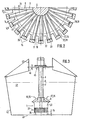
- the device generally designated 1 in the figures, consists of a rotor, generally designated 2, which is mounted in a tubular stator 4 so as to be rotatable about an axis of rotation 3.
- the rotor 2 has a plurality of radially extending rotor blades 5 and is fastened to a vertically extending drive shaft 6, which is arranged within a protective tube 7 which carries the stator 4 and is connected to the latter by means of radially extending struts 8.
- the stator 4 consists of a vertically arranged tube 9 which is expanded in the shape of a trumpet on the upper side and with these edges 11 delimits an inlet, generally designated 12, for the materials to be treated.
- the struts 8 pass through this inlet 12 and connect the tube 9 to a sleeve 13 which is fastened on the protective tube 7.
- the tube 9 of the stator 4 is drawn in in the form of a radially extending annular wall 14 which encloses an outlet 15.
- the hollow cylindrical Wall section of the tube 9 and the annular wall 14 form a corner or inner shoulder of the stator 4, in which the rotor 2 is arranged.
- baffle plate 19 is axially adjustable in a manner not shown and can be locked in the respective position.
- the adjustability of the baffle plate 19 is shown by a double arrow 21.
- the diameter d of the rotor 2 is dimensioned so large that there is only a small gap s between the inner wall 22 of the tube 9 and the lateral surfaces 23 of the rotor 2. This gap s also extends between the side 24 of the rotor facing the outlet 15 and the inside 25 of the ring wall 14. Between the inside wall 22 and the inside 25 of the stator 4 and the lateral surface 23 and the side 24 of the rotor 2, a generally arises Scherfeld designated 26, the stator side shear edges 27 are formed by the inner edges 28 and its rotor-side shear edges 29 by the outer edges 31 and the side edges 32 of the rotor 2.
- the rotor blades 5 are set. This can be seen on the inclined side surfaces, which are designated by 33 in FIG. 2. Due to the setting of the rotor blades 5 of the rotor 2 rotating during operation in the direction of the arrow 34, the material to be treated, which consists of at least two different substances or media, is sucked into the stator 4 in the direction of the arrows 35 through the inlet 12. In the area of the rotor 2, the material is intimately mixed with one another, and it divides into an axial, generally 36 and a radial, generally 37 partial flow due to two feed forces. The partial flows are identified by radial and axial arrows.
- the axial partial flow 36 is a ring flow, and it is based on axial feed or acceleration forces which are caused by the setting of the rotor blades 5.
- the radial partial flow 37 spreads from the entire circumference of the stator 4 and is based on feed or acceleration forces which are caused by the centrifugal force of the material parts rotating with the rotor 2.
- Those located in the axial partial flow 36 Materials are mainly mixed intensively with one another, while the materials located in the radial partial flow 37 are subject to strong shear and impact effects in the shear field 26, as a result of which the desired dispersion and emulsification is effected.
- the proportion of the dispersion work in the radial partial flow 37 can be controlled by appropriate dimensioning of the distance a between the baffle plate 19 and the ring wall 14.
- the distance a determining the cross section of the outlet 15 should be selected to be relatively large. This is e.g. B. the case when light substances are to be incorporated, for. B. powders, which require a relatively large suction to pull them down from the surface of the material to be treated in the area of the stator.
- the baffle plate 19 differs from the one described above only in that the baffle plate 19 is not present.
- the device 1 for controlling the desired amount of dispersion or mixing work relative to the bottom 43 of the container 42 is axially adjusted.
- the proportion of the dispersion work is also determined by the size or length 1 of the slots 16. In the present exemplary embodiments, the length 1 corresponds to the width f of the rotor 2.
- the axial adjustment of the device 1 is expediently carried out by means of a holding device 45 which supports it and which can be displaced vertically (double arrow 46) in a guide 47 by means of an actuator (not shown).
- the actuator can e.g. B. be a pneumatically or hydraulically expandable actuating cylinder.
Landscapes
- Chemical & Material Sciences (AREA)
- Chemical Kinetics & Catalysis (AREA)
- Mixers Of The Rotary Stirring Type (AREA)
- Coating Apparatus (AREA)
Priority Applications (1)
| Application Number | Priority Date | Filing Date | Title |
|---|---|---|---|
| AT86106666T ATE82873T1 (de) | 1985-05-15 | 1986-05-15 | Vorrichtung zum mischen und dispergieren mindestens zweier medien. |
Applications Claiming Priority (2)
| Application Number | Priority Date | Filing Date | Title |
|---|---|---|---|
| DE3517655 | 1985-05-15 | ||
| DE19853517655 DE3517655A1 (de) | 1985-05-15 | 1985-05-15 | Vorrichtung zum mischen und dispergieren mindestens zweier medien |
Publications (3)
| Publication Number | Publication Date |
|---|---|
| EP0201927A2 true EP0201927A2 (fr) | 1986-11-20 |
| EP0201927A3 EP0201927A3 (en) | 1988-05-18 |
| EP0201927B1 EP0201927B1 (fr) | 1992-12-02 |
Family
ID=6270889
Family Applications (1)
| Application Number | Title | Priority Date | Filing Date |
|---|---|---|---|
| EP86106666A Expired - Lifetime EP0201927B1 (fr) | 1985-05-15 | 1986-05-15 | Dispositif pour mélanger et disperser au moins deux milieux |
Country Status (4)
| Country | Link |
|---|---|
| US (1) | US4738543A (fr) |
| EP (1) | EP0201927B1 (fr) |
| AT (1) | ATE82873T1 (fr) |
| DE (2) | DE3517655A1 (fr) |
Cited By (3)
| Publication number | Priority date | Publication date | Assignee | Title |
|---|---|---|---|---|
| RU2162733C1 (ru) * | 1999-06-15 | 2001-02-10 | Тамбовский государственный технический университет | Реактор-полимеризатор |
| WO2013064663A1 (fr) * | 2011-11-02 | 2013-05-10 | Fresenius Kabi Deutschland Gmbh | Dispositif et procédé pour préparer une composition fluide pour nutrition entérique complète ou de supplémentation |
| EP2939734A4 (fr) * | 2012-12-25 | 2016-08-24 | M Tech Co Ltd | Dispositif et procédé de mélange |
Families Citing this family (6)
| Publication number | Priority date | Publication date | Assignee | Title |
|---|---|---|---|---|
| WO1990014880A1 (fr) * | 1989-05-03 | 1990-12-13 | Ullrich, Manfred | Dispositif melangeur pour fluides |
| DE4118870A1 (de) * | 1991-06-07 | 1992-12-17 | Ystral Gmbh Maschinenbau Und P | Vorrichtung zum benetzen und dispergieren von pulvern in fluessigkeiten |
| US6863431B2 (en) * | 1992-03-30 | 2005-03-08 | Omni International, Inc. | Disruptor device which eliminates cross contamination |
| SG11201800144QA (en) | 2015-08-06 | 2018-02-27 | Meiji Co Ltd | Atomization device and method for manufacturing product with fluidity using said device |
| DE102016103968B4 (de) | 2016-03-04 | 2019-01-17 | Alexander Westphal | Rührer, insbesondere Leitstrahlmischer und Rühreinrichtung umfassend einen Rührer |
| US11241661B2 (en) * | 2019-04-15 | 2022-02-08 | M. Technique Co., Ltd. | Stirrer |
Family Cites Families (10)
| Publication number | Priority date | Publication date | Assignee | Title |
|---|---|---|---|---|
| US2875897A (en) * | 1953-06-22 | 1959-03-03 | Booth Lionel Earl | Flotation machine |
| US2985389A (en) * | 1955-09-02 | 1961-05-23 | Willems Peter | Apparatus for physical and/or chemical treatment of materials |
| DE1219447B (de) * | 1963-11-22 | 1966-06-23 | Karg G M B H Dr | Mischkopf zum Homogenisieren u. dgl. von Medien fluessiger bis hochviskoser Konsistenz |
| US3724765A (en) * | 1971-09-03 | 1973-04-03 | Beckman Instruments Inc | Tablet disruptor device |
| DE2310321B1 (de) * | 1973-03-01 | 1974-01-31 | Int Laboratoriums App Gmbh | Emulgier- und dispergiervorrichtung mit rotierenden konzentrischen werkzeugkraenzen |
| GB1518144A (en) * | 1975-07-04 | 1978-07-19 | Pilkington Brothers Ltd | Glass fibre reinforced cement composite materials |
| DE2702183A1 (de) * | 1977-01-20 | 1978-07-27 | Ystral Gmbh Maschinenbau Und P | Misch- und dispergiervorrichtung |
| US4437765A (en) * | 1982-03-05 | 1984-03-20 | Ystral Gmbh | Dispersion turbine |
| DE3220092A1 (de) * | 1982-05-28 | 1983-12-01 | Janke & Kunkel GmbH & Co KG Ika - Werk, 7813 Staufen | Dispergiervorrichtung |
| GB2165462B (en) * | 1984-10-10 | 1988-02-03 | Unishear Mixers Ltd | Mixing apparatus stator device |
-
1985
- 1985-05-15 DE DE19853517655 patent/DE3517655A1/de active Granted
-
1986
- 1986-05-15 DE DE8686106666T patent/DE3687183D1/de not_active Expired - Lifetime
- 1986-05-15 US US06/863,702 patent/US4738543A/en not_active Expired - Lifetime
- 1986-05-15 EP EP86106666A patent/EP0201927B1/fr not_active Expired - Lifetime
- 1986-05-15 AT AT86106666T patent/ATE82873T1/de active
Cited By (5)
| Publication number | Priority date | Publication date | Assignee | Title |
|---|---|---|---|---|
| RU2162733C1 (ru) * | 1999-06-15 | 2001-02-10 | Тамбовский государственный технический университет | Реактор-полимеризатор |
| WO2013064663A1 (fr) * | 2011-11-02 | 2013-05-10 | Fresenius Kabi Deutschland Gmbh | Dispositif et procédé pour préparer une composition fluide pour nutrition entérique complète ou de supplémentation |
| EP2939734A4 (fr) * | 2012-12-25 | 2016-08-24 | M Tech Co Ltd | Dispositif et procédé de mélange |
| JPWO2014102906A1 (ja) * | 2012-12-25 | 2017-01-12 | エム・テクニック株式会社 | 攪拌処理装置及び処理方法 |
| US9925503B2 (en) | 2012-12-25 | 2018-03-27 | M. Technique Co., Ltd. | Stirring-processing apparatus and processing method |
Also Published As
| Publication number | Publication date |
|---|---|
| DE3687183D1 (de) | 1993-01-14 |
| US4738543A (en) | 1988-04-19 |
| EP0201927B1 (fr) | 1992-12-02 |
| ATE82873T1 (de) | 1992-12-15 |
| DE3517655A1 (de) | 1986-11-20 |
| EP0201927A3 (en) | 1988-05-18 |
| DE3517655C2 (fr) | 1987-07-16 |
Similar Documents
| Publication | Publication Date | Title |
|---|---|---|
| DE2655901C2 (fr) | ||
| DE69124571T2 (de) | Emulgierverfahren und -vorrichtung | |
| DE10204921C1 (de) | Dispergier-Vorrichtung | |
| DE9106768U1 (de) | Begasungsrührer | |
| DE1213385B (de) | Mischmaschine | |
| DE3243671C2 (fr) | ||
| DE1457270B2 (de) | Fluessigkeitsmischer | |
| EP0201927B1 (fr) | Dispositif pour mélanger et disperser au moins deux milieux | |
| DE68904086T2 (de) | Herstellung einer waessrigen dispersion einer viskosen fluessigkeit. | |
| EP3202489A2 (fr) | Dispositif mélangeur et/ou de pompage destiné à acheminer, homogénéiser et/ou disperser des produits coulant | |
| WO1992021436A1 (fr) | Dispositif de dispersion, suspension ou emulsion de gaz, liquides et/ou matieres solides coulantes | |
| DE3342304A1 (de) | Homogenisiermaschine | |
| DE1557184A1 (de) | Vorrichtung zum kontinuierlichen Mischen,Homogenisieren und Belueften von pastoesen Massen,insbesondere Schokoladenmassen | |
| DE3738223C2 (de) | Vorrichtung zum intensiven Mischen von Flüssigkeiten oder eines Flüssigkeits-Feststoff-Gemisches, zum Behandeln von Wasser, wässrigen Lösungen oder anderen Flüssigkeiten und Schmelzen | |
| DE6910964U (de) | Mischvorrichtung | |
| DE2236200C3 (de) | GieBerefmischmaschine zum Mischen eines körnigen oder pulverförmigen Formmaterials mit flüssigem Binder | |
| DE2740789C2 (de) | Vorrichtung zum kontinuierlichen mechanischen Vermischen von zwei Komponenten | |
| DE69309932T2 (de) | Vorrichtung zum beimischen von behandlungsmittel zu einer zellstoffsuspension | |
| EP3334519B1 (fr) | Dispositif et procédé destinés à la dispersion d'au moins une substance dans un fluide | |
| EP0475015A1 (fr) | Procédé et appareil pour le broyage continu et la dispersion de solides dans des liquides | |
| DE3002429C2 (fr) | ||
| DE3016374C2 (de) | Dispergierturbine | |
| EP0572610B1 (fr) | Procede visant a disperser, melanger ou homogeniser des melanges et dispositif d'application dudit procede | |
| DE1457270C (de) | Flüssigkeitsmischer | |
| CH364492A (de) | Emulgiervorrichtung |
Legal Events
| Date | Code | Title | Description |
|---|---|---|---|
| PUAI | Public reference made under article 153(3) epc to a published international application that has entered the european phase |
Free format text: ORIGINAL CODE: 0009012 |
|
| AK | Designated contracting states |
Kind code of ref document: A2 Designated state(s): AT BE CH DE FR GB IT LI LU NL SE |
|
| PUAL | Search report despatched |
Free format text: ORIGINAL CODE: 0009013 |
|
| AK | Designated contracting states |
Kind code of ref document: A3 Designated state(s): AT BE CH DE FR GB IT LI LU NL SE |
|
| 17P | Request for examination filed |
Effective date: 19880701 |
|
| 17Q | First examination report despatched |
Effective date: 19891027 |
|
| GRAA | (expected) grant |
Free format text: ORIGINAL CODE: 0009210 |
|
| AK | Designated contracting states |
Kind code of ref document: B1 Designated state(s): AT BE CH DE FR GB IT LI LU NL SE |
|
| PG25 | Lapsed in a contracting state [announced via postgrant information from national office to epo] |
Ref country code: IT Free format text: LAPSE BECAUSE OF FAILURE TO SUBMIT A TRANSLATION OF THE DESCRIPTION OR TO PAY THE FEE WITHIN THE PRE;WARNING: LAPSES OF ITALIAN PATENTS WITH EFFECTIVE DATE BEFORE 2007 MAY HAVE OCCURRED AT ANY TIME BEFORE 2007. THE CORRECT EFFECTIVE DATE MAY BE DIFFERENT FROM THE ONE RECORDED.SCRIBED TIME-LIMIT Effective date: 19921202 Ref country code: BE Effective date: 19921202 Ref country code: SE Effective date: 19921202 Ref country code: NL Effective date: 19921202 |
|
| REF | Corresponds to: |
Ref document number: 82873 Country of ref document: AT Date of ref document: 19921215 Kind code of ref document: T |
|
| GBT | Gb: translation of ep patent filed (gb section 77(6)(a)/1977) |
Effective date: 19921201 |
|
| REF | Corresponds to: |
Ref document number: 3687183 Country of ref document: DE Date of ref document: 19930114 |
|
| ET | Fr: translation filed | ||
| PG25 | Lapsed in a contracting state [announced via postgrant information from national office to epo] |
Ref country code: AT Effective date: 19930515 |
|
| NLV1 | Nl: lapsed or annulled due to failure to fulfill the requirements of art. 29p and 29m of the patents act | ||
| PG25 | Lapsed in a contracting state [announced via postgrant information from national office to epo] |
Ref country code: LU Free format text: LAPSE BECAUSE OF NON-PAYMENT OF DUE FEES Effective date: 19930531 |
|
| PLBE | No opposition filed within time limit |
Free format text: ORIGINAL CODE: 0009261 |
|
| STAA | Information on the status of an ep patent application or granted ep patent |
Free format text: STATUS: NO OPPOSITION FILED WITHIN TIME LIMIT |
|
| 26N | No opposition filed | ||
| REG | Reference to a national code |
Ref country code: GB Ref legal event code: IF02 |
|
| PGFP | Annual fee paid to national office [announced via postgrant information from national office to epo] |
Ref country code: GB Payment date: 20050503 Year of fee payment: 20 |
|
| PGFP | Annual fee paid to national office [announced via postgrant information from national office to epo] |
Ref country code: FR Payment date: 20050519 Year of fee payment: 20 |
|
| PGFP | Annual fee paid to national office [announced via postgrant information from national office to epo] |
Ref country code: CH Payment date: 20050524 Year of fee payment: 20 |
|
| REG | Reference to a national code |
Ref country code: GB Ref legal event code: PE20 |
|
| PGFP | Annual fee paid to national office [announced via postgrant information from national office to epo] |
Ref country code: DE Payment date: 20050729 Year of fee payment: 20 |
|
| PG25 | Lapsed in a contracting state [announced via postgrant information from national office to epo] |
Ref country code: GB Free format text: LAPSE BECAUSE OF EXPIRATION OF PROTECTION Effective date: 20060514 |
|
| REG | Reference to a national code |
Ref country code: CH Ref legal event code: PL |