EP0201942A1 - Dispositif de levée des bobines pour métiers à filer à anneau - Google Patents
Dispositif de levée des bobines pour métiers à filer à anneau Download PDFInfo
- Publication number
- EP0201942A1 EP0201942A1 EP86200317A EP86200317A EP0201942A1 EP 0201942 A1 EP0201942 A1 EP 0201942A1 EP 86200317 A EP86200317 A EP 86200317A EP 86200317 A EP86200317 A EP 86200317A EP 0201942 A1 EP0201942 A1 EP 0201942A1
- Authority
- EP
- European Patent Office
- Prior art keywords
- gripper
- yarn packages
- tubes
- spindle
- grippers
- Prior art date
- Legal status (The legal status is an assumption and is not a legal conclusion. Google has not performed a legal analysis and makes no representation as to the accuracy of the status listed.)
- Granted
Links
- 238000007378 ring spinning Methods 0.000 title claims abstract description 5
- 238000009987 spinning Methods 0.000 description 14
- 239000012528 membrane Substances 0.000 description 3
- 210000002268 wool Anatomy 0.000 description 3
- 230000001174 ascending effect Effects 0.000 description 1
- 230000015572 biosynthetic process Effects 0.000 description 1
- 230000009347 mechanical transmission Effects 0.000 description 1
- 230000003534 oscillatory effect Effects 0.000 description 1
- 238000012856 packing Methods 0.000 description 1
- 238000007789 sealing Methods 0.000 description 1
Images

Classifications
-
- D—TEXTILES; PAPER
- D01—NATURAL OR MAN-MADE THREADS OR FIBRES; SPINNING
- D01H—SPINNING OR TWISTING
- D01H9/00—Arrangements for replacing or removing bobbins, cores, receptacles, or completed packages at paying-out or take-up stations ; Combination of spinning-winding machine
- D01H9/02—Arrangements for replacing or removing bobbins, cores, receptacles, or completed packages at paying-out or take-up stations ; Combination of spinning-winding machine for removing completed take-up packages and replacing by bobbins, cores, or receptacles at take-up stations; Transferring material between adjacent full and empty take-up elements
- D01H9/04—Doffing arrangements integral with spinning or twisting machines
Definitions
- This invention concerns a device to doff yarn packages on ring spinning machines. To be more exact, the invention concerns a device to doff yarn packages and to replace them with empty tubes taken from appropriate temporary lodgement stations.
- the device of the invention is intended in particular, but not only, for machines to spin carded wool.
- Such known automatic systems comprise mechanical devices located in the part of the machine which includes the spindles. The zone of the spindles is therefore unavoidably occupied by such devices in their waiting position while the spindles are working. Access to the machine is therefore restricted.
- creels are employed which can take and extract the yarn packages from the spindles; means are also used which can take the tubes from an appropriate station or stock generally positioned in the lower part of the spinning machine and can load such tubes onto the spindles.
- Patent DE-A-1.934.358 discloses a complicated device comprising a gripper able to move vertically by means of a system of chains.
- a container for a reserve tube is provided and is solidly fixed to the gripper, such tube has to be inserted into this container by hand beforehand.
- the gripper can be displaced transversely so that when the yarn package has been removed from the spindle, the container can be brought into position, with the tube above the spindle.
- the whole gripper can be overturned by 180° to perform discharge of the yarn package outside the spinning machine.
- This device entails the drawback of a stationary bulky mass in correspondence with the zone of the spindles,owing to the chain that moves the gripper and the relative stationary supports.
- the device is very complicated as regards its mechanical structure and also as regards the many movements and relative actuation systems required.
- the device has to carry out two vertical movements. which involve long change-over times.
- TEXTIL-PRAXIS of January 1964 discloses on page 15 a device produced by Jacobi & Co., which is equipped with a double gripper to doff the yarn packages and insert the tubes.
- the tube is held in this device by a mechanical coupler, which is only suitable for grooved tubes.
- the double gripper includes two grippers at 90° to each other.
- the yarn package is engaged by a movement of inclination of the relative gripper, which creates a mechanical joint.
- the yarn package has been doffed from the spindle, it falls on its own out of the gripper into a discharge position. This device performs a whole series of movements and is therefore very complicated.
- the two grippers cannot only move, solidly fixed to each other, about an axis but can also move reciprocally, one being superimposed on the other during the step of release of the tube on the spindle.
- the empty tubes in the reserve position are low down in the zone of the spindles and are inserted into the grippers by hand.
- the device entails a stationary bulky mass in the zone of the spindles.
- Patent DE-A-2613900 in the name of- Toyoda discloses a complex device including a movable and inclinable rail which is able to take tubes from a low reserve position, to bring them above the yarn packages and at the same time to engage an empty tube and the top of the yarn package, to withdraw the yarn package from the spindle and discharge it in a reserve position, and then to take the empty tube back to the zone of the spindles and position it on the spindle itself.
- This device entails a whole series of movements and, in particular, a double vertical travel, besides the required inclination of the whole movable rail.
- this device too creates a stationary bulky mass in the zone of the spindles, thus restricting accessibility to the spindles.
- Patent FR-A-1.173.911 discloses a device with grippers to withdraw the yarn package and the tube by gripping them, the grippers consisting of a rubber membrane with toothed engagement apertures.
- This device has a very complex actuation system with programming cams and mechanical transmission means to move the grippers; it also creates a stationary irremovable bulky mass at the front of the spinning machine.
- Patent CH-A-84427 discloses a device with a gripper producing a resilient grip provided by resilient blades.
- the gripper can be rotated by 180° to exchange an empty tube for the yarn package doffed from the spindle.
- This gripper can also be raised and lowered by worm-screw means.
- the overall device can be turned over completely by 180° so as to take the gripper, together with a full yarn package doffed from the spindle, to a position suitable for withdrawal of the yarn package by the machine operative.
- the device works slowly and performs not only the rotary movement for overturning the grippers and the vertical movement of the grippers themselves but also the cited movement of overturning of the whole device by the worm-screw so as to bring the yarn packages to a position where they can be withdrawn by hand.
- the device is therefore slow and complicated and also creates a permanent bulky mass in the zone of the spindles.
- Patent US-A-2,716,326 discloses a very complicated doffing device consisting of a movable rail with overturnable grippers to engage the yarn packages.
- the grippers which are normally lodged below the zone of the spindles in their inactive position, are moved by actuation cams along a complicated path with a plurality of movements and relative actuation systems.
- the raising takes place by means of a worm-screw and is therefore slow.
- the device comprises also a stationary framework of considerable vertical and transverse bulk.
- One purpose of this invention is therefore to provide a device to replace yarn packages with empty tubes which changes the yarn packages particularly quickly and efficiently.
- Another purpose of the invention is to provide a device which has a mainly vertical development and is :ch that it normally stays above the zone of the spindles, thus leaving that zone completely free and accessible.
- the invention obtains the above purposes owing to the fact that a double gripper is provided which can withdraw the yarn packages and can bear tubes taken from a conveyor, such as a conveyor belt for instance, arranged above the spinning machine.
- the gripper normally stays above the zone of the spindles.
- the position for taking the empty tubes and consigning the completed yarn packages is such as to enable the movement of the gripper to overlap the stoppage and start-up of the spindles partially in time.
- the spindles can be started up well before the gripper has reached the position for consigning the yarn packages. This shortens the downtimes of the machine considerably and therefore enables output to be increased to a great extent.
- the gripper can bear a yarn package and a tube in appropriate engagement means at one and the same time and can rotate about a shaft so as to exchange the respective positions of the completed yarn package and of the tube.
- such gripper can move vertically to extract the yarn package from the spindle, to take a new tube and lodge it on the spindle and also to place the yarn package on a removal conveyor, which will advantageously be the conveyor that feeds the tubes but may also be a separate conveyor.
- the gripper can rotate aLout a horizontal shaft and the change-over of the respective positions of the yarn package and tube is carried out by a 180° rotation of the gripper about such shaft after the gripper has been raised to a position where it will not come into contact with the elements of the spinning machine.
- This invention is therefore embodied with a device to doff yarn packages on ring spinning machines which is able to doff the yarn packages automatically and to replace them with empty tubes, and which comprises a movable gripper, a station to engage tubes and means to remove yarn packages and is characterized in that the gripper comprises an element to engage yarn packages and an element to engage tubes, such gripper being able to rotate about a horizontal shaft so as to bring one or the other engagement element to cooperate with the spindle shaft momentarily, the gripper being able to move vertically and normally staying in a position where it does not interfere with the zone of the spindle.
- a device 10 to doff yarn packages according to the invention is borne on a stationary structure 11 solidly fixed to a spinning machine 12 shown diagrammatically.
- a spindle 13 and relative actuation means, a ring carriage 14 and a completed yarn package 15 on the spinning machine 12 can be seen.
- the device 10 comprises essentially a double gripper 17 able to take and support the yarn package 15 and a tube 16 at one and the same time.
- the gripper 17 is supported rotatably by an arm 18, which can move vertically by means of a telescopic guide 19, which may consist of one or more slidable elements moved by cables, ropes or chains or other analogous means, for instance.
- a conveyor 20 to deliver tubes 16 can be seen above the spinning machine 12.
- the tubes 16 are taken from this conveyor 20 at position 17B of the gripper 17.
- the conveyor 20 is equipped with retractable pins known in themselves and therefore not shown, or with other analogous means to bear the tubes 16 and thereafter the yarn packages 15 consigned to such pins.
- a conveyor 21 can also be seen which feeds packages 22 of carded wool to the spinning machine 12; such packages 22 are placed in their working position 22A.
- the device 10 works in the following manner: when the yarn package 15 has been completed, the gripper 17, which is in its upper position 17B and has engaged a tube 16, descends until it engages the yarn package 15. The spindles are halted during this descent.
- the gripper-bearing shaft 24 then ascends once more by means of the telescopic guide 19 until it has brought the gripper 17 to position 17A at a height great enough to prevent any contact with the elements of the spinning machine 12.
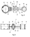
- the gripper 17 is now rotated by 180° about the horizontal shaft 24 (see also Fig.2).
- Such shaft 24 serves all the grippers 17, actuation being provided by one single actuator of any known type, such as an electric motor, a jack or the like.
- the gripper 17 is now lowered again until it has brought the new tube 16 to be lodged on the spindle 13. The gripper 17 is then opened to release the tube 16 on the spindle 13.
- the gripper ascends again; when the gripper has reached a position far enough from the spindle 13, the latter is started up and thus begins a new spinning cycle.
- the gripper 17 then continues ascending until it has consigned the yarn package 15 to the conveyor belt 20.
- the gripper now opens, releases the yarn package and descends enough not to interfere with the movement of the conveyor 20, which now bears the yarn packages to be removed.
- the gripper 17 rises to 17B and engages the tubes so as to begin a new cycle.
- the tubes 16 can be placed on the conveyor 20 automatically or by hand. For instance, a station for loading the conveyor will be included, being already known in itself.
- the above doffing cycle requires a very short time to be accomplished, as compared to the known embodiments. This is made possible by the partial overlapping in time of the rotation of the spindles with the movements of the gripper, such movements, as we have said, providing for a vertical movement towards the spindle to take the yarn package, another vertical travel upwards to reach the position of rotation 17A of the gripper, a further downward vertical movement to place the tube 16 on the spindle 13 and a further ascent of the gripper 17 to consign the yarn package, plus a slight lowering of the gripper so as not to contact the conveyor 20 during removal and a subsequent re-positioning at 17B. Normally, that is, during formation of the yarn package 15, the gripper 17 will stay at position 17B in the example shown.
- Figs.2 and 3 show a preferred embodiment of the gripper 17.
- the gripper shown consists of a gripper body 23 solidly fixed to the shaft 24 which actuates rotation of such gripper.
- the gripper 17 comprises an element 25 to engage yarn packages and an element 26 to engage tubes, such elements being located on opposite sides of the shaft 24.
- Such elements 25-26 have a substantially cylindrical shape and comprise, on their inner side, membranes 27-127 respectively.
- membranes 27-127 can be expanded in a known manner by compressed air delivered through respective feed ducts 29 and 129 and respective delivery channels 28 and 128.
- the feed ducts 29-129 are provided in the form of lengthwise grooves in the shaft 24, such grooves being closed with strips of rod 30 bored in correspondence with the channels 28-128. Sealing packings are positioned in correspondence with the bored holes.
Landscapes
- Engineering & Computer Science (AREA)
- Mechanical Engineering (AREA)
- Textile Engineering (AREA)
- Spinning Or Twisting Of Yarns (AREA)
- Unwinding Of Filamentary Materials (AREA)
- Yarns And Mechanical Finishing Of Yarns Or Ropes (AREA)
Priority Applications (1)
| Application Number | Priority Date | Filing Date | Title |
|---|---|---|---|
| AT86200317T ATE43866T1 (de) | 1985-03-26 | 1986-03-01 | Abziehvorrichtung fuer garntragkoerper in ringspinnmaschinen. |
Applications Claiming Priority (2)
| Application Number | Priority Date | Filing Date | Title |
|---|---|---|---|
| IT8334985 | 1985-03-26 | ||
| IT83349/85A IT1187551B (it) | 1985-03-26 | 1985-03-26 | Dispositivo di levata spole per filatoi ad anelli |
Publications (2)
| Publication Number | Publication Date |
|---|---|
| EP0201942A1 true EP0201942A1 (fr) | 1986-11-20 |
| EP0201942B1 EP0201942B1 (fr) | 1989-06-07 |
Family
ID=11320537
Family Applications (1)
| Application Number | Title | Priority Date | Filing Date |
|---|---|---|---|
| EP86200317A Expired EP0201942B1 (fr) | 1985-03-26 | 1986-03-01 | Dispositif de levée des bobines pour métiers à filer à anneau |
Country Status (6)
| Country | Link |
|---|---|
| US (1) | US4682466A (fr) |
| EP (1) | EP0201942B1 (fr) |
| JP (1) | JPS61225335A (fr) |
| AT (1) | ATE43866T1 (fr) |
| DE (1) | DE3663826D1 (fr) |
| IT (1) | IT1187551B (fr) |
Cited By (2)
| Publication number | Priority date | Publication date | Assignee | Title |
|---|---|---|---|---|
| EP0467862A1 (fr) * | 1990-07-13 | 1992-01-22 | S. BIGAGLI & C. SpA | Méthode et dispositif pour l'enlèvement de bobines d'un métier à filer et pour la casse du fil |
| WO2017085588A1 (fr) * | 2015-11-19 | 2017-05-26 | Maschinenfabrik Rieter Ag | Dispositif de levée à double élément de préhension pour un métier à filer |
Citations (5)
| Publication number | Priority date | Publication date | Assignee | Title |
|---|---|---|---|---|
| CH84427A (de) * | 1919-07-09 | 1920-08-02 | Friedrich Graf | Vorrichtung für mit Spulen arbeitende Maschinen, wie Spinnereimaschinen und dergleichen, um von den Spindeln der Spindelbänke die vollen Spulen zu entfernen und dieselben gleichzeitig mit leeren Spulen zu versehen |
| US2716326A (en) * | 1951-05-12 | 1955-08-30 | Callaway Mills Co | Doffing and donning apparatus |
| FR1173911A (fr) * | 1955-07-12 | 1959-03-04 | Mécanisme entièrement automatique pour changer les canettes dans des machines à filer continues et similaires | |
| DE1934358A1 (de) * | 1968-07-08 | 1970-01-15 | Edera Off Mec Tessili | Automatische mechanische Abzieh- und Aufsteckvorrichtung fuer Garntragkoerper in Spinn-Zwirnmaschinen u.dgl. |
| DE2613900A1 (de) * | 1975-03-31 | 1976-10-07 | Toyoda Automatic Loom Works | Verfahren zum aufsetzen und abnehmen von spulen an spinnmaschinen und vorrichtung zur durchfuehrung des verfahrens |
Family Cites Families (5)
| Publication number | Priority date | Publication date | Assignee | Title |
|---|---|---|---|---|
| US1463479A (en) * | 1921-10-29 | 1923-07-31 | William W Miller | Doffing and donning mechanism |
| DE1218916B (de) * | 1963-02-09 | 1966-06-08 | Mechanische Baumwoll Spinnerei | Greifer zum Abziehen von Spinnkopsen an Ringspinnmaschinen, Zwirnmaschinen u. dgl. |
| DE2309754A1 (de) * | 1972-03-16 | 1973-09-27 | Nuova San Giorgio Spa | Greifvorrichtung fuer das abnehmen der vollen spulen und das wiedereinsetzen der leeren huelsen in einer spinnmaschine |
| JPS5221092A (en) * | 1975-08-11 | 1977-02-17 | Kanegafuchi Chem Ind Co Ltd | Resin compositions with a low shrinkage |
| IT1153043B (it) * | 1982-11-16 | 1987-01-14 | Mec Tessile Edera S P A Off | Dispositivo di levata automatica per filatoi e/o ritorcitoi ad anello, in particolare nelle macchine per produzione di grosse confezioni |
-
1985
- 1985-03-26 IT IT83349/85A patent/IT1187551B/it active
-
1986
- 1986-03-01 AT AT86200317T patent/ATE43866T1/de not_active IP Right Cessation
- 1986-03-01 DE DE8686200317T patent/DE3663826D1/de not_active Expired
- 1986-03-01 EP EP86200317A patent/EP0201942B1/fr not_active Expired
- 1986-03-20 US US06/841,782 patent/US4682466A/en not_active Expired - Lifetime
- 1986-03-26 JP JP61068279A patent/JPS61225335A/ja active Pending
Patent Citations (5)
| Publication number | Priority date | Publication date | Assignee | Title |
|---|---|---|---|---|
| CH84427A (de) * | 1919-07-09 | 1920-08-02 | Friedrich Graf | Vorrichtung für mit Spulen arbeitende Maschinen, wie Spinnereimaschinen und dergleichen, um von den Spindeln der Spindelbänke die vollen Spulen zu entfernen und dieselben gleichzeitig mit leeren Spulen zu versehen |
| US2716326A (en) * | 1951-05-12 | 1955-08-30 | Callaway Mills Co | Doffing and donning apparatus |
| FR1173911A (fr) * | 1955-07-12 | 1959-03-04 | Mécanisme entièrement automatique pour changer les canettes dans des machines à filer continues et similaires | |
| DE1934358A1 (de) * | 1968-07-08 | 1970-01-15 | Edera Off Mec Tessili | Automatische mechanische Abzieh- und Aufsteckvorrichtung fuer Garntragkoerper in Spinn-Zwirnmaschinen u.dgl. |
| DE2613900A1 (de) * | 1975-03-31 | 1976-10-07 | Toyoda Automatic Loom Works | Verfahren zum aufsetzen und abnehmen von spulen an spinnmaschinen und vorrichtung zur durchfuehrung des verfahrens |
Non-Patent Citations (1)
| Title |
|---|
| TEXTIL-PRAXIS, no. 1, 1964, page 13; "Die Arbeitsphasen der stationären Kopsabziehvorrichtung "Jacotex"" * |
Cited By (3)
| Publication number | Priority date | Publication date | Assignee | Title |
|---|---|---|---|---|
| EP0467862A1 (fr) * | 1990-07-13 | 1992-01-22 | S. BIGAGLI & C. SpA | Méthode et dispositif pour l'enlèvement de bobines d'un métier à filer et pour la casse du fil |
| WO2017085588A1 (fr) * | 2015-11-19 | 2017-05-26 | Maschinenfabrik Rieter Ag | Dispositif de levée à double élément de préhension pour un métier à filer |
| US10954610B2 (en) | 2015-11-19 | 2021-03-23 | Maschinenfabrik Rieter Ag | Doffer device having a double gripper for a spinning machine |
Also Published As
| Publication number | Publication date |
|---|---|
| US4682466A (en) | 1987-07-28 |
| DE3663826D1 (en) | 1989-07-13 |
| JPS61225335A (ja) | 1986-10-07 |
| IT8583349A0 (it) | 1985-03-26 |
| ATE43866T1 (de) | 1989-06-15 |
| IT1187551B (it) | 1987-12-23 |
| EP0201942B1 (fr) | 1989-06-07 |
Similar Documents
| Publication | Publication Date | Title |
|---|---|---|
| US3788054A (en) | Apparatus for transporting and storing yarn pirns or the like | |
| US4586326A (en) | Spinning machine with roving-bobbin feeder | |
| US3905184A (en) | Apparatus for simultaneously doffing and donning apparatus | |
| US5568720A (en) | Apparatus for servicing a multi-position yarn winding machine | |
| US4817373A (en) | Apparatus for automatically supplying continuous spinning machines with reeled material | |
| US4389840A (en) | Method of automatically doffing the full bobbin packages from, and donning the empty bobbin tubes onto, the spindles of a preparatory spinning machine | |
| US5083716A (en) | Device and method for automatically doffing bobbins in a winding machine | |
| US3681906A (en) | Method and apparatus for doffing full bobbins and donning tubes on ring spinning and ring twisting machines | |
| US5316126A (en) | System for conveying packages | |
| US5495991A (en) | Apparatus for transporting empty yarn winding tubes and fully wound textile yarn packages to and from a winding location | |
| EP0201942B1 (fr) | Dispositif de levée des bobines pour métiers à filer à anneau | |
| EP0112303B1 (fr) | Dispositif automatique pour le remplacement simultané des bobines pleines sur un métier à filer ou à retordre | |
| EP0919505A1 (fr) | Dispostif de bobinage en particulier pour fils textiles | |
| EP0276569B1 (fr) | Procédé et dispositif de transport d'articles | |
| EP0310567B1 (fr) | Dispositif dans un banc à broches pour remplacer automatiquement des bobines de mèche contre des tubes de bobine pour l'enroulement de la mèche | |
| EP0014527A2 (fr) | Changeur automatique de bobine sur bobinoirs | |
| US3370412A (en) | Apparatus for use in connection with two-for-one twisting machines for automatically changing bobbin units | |
| US5022223A (en) | Method of and apparatus for automatically exchanging bobbins at a flyer | |
| EP0299934B1 (fr) | Dispositif automatique pour la levée de canettes et l'insertion de tubes de bobines ainsi que le remplacement de bobines de mèche dans les renvideurs | |
| US4571930A (en) | Automatic doffing device for ring spinning and/or twisting frames, in particular in machines for producing large packages | |
| EP0452687A1 (fr) | Procédé pour l'alimentation de pots de ruban aux machines textiles, et dispositif pour la mise en oeuvre de ce procédé | |
| GB2155510A (en) | Automatic doffing device for ring spinning and/or twisting frames, in particular in machines for producing large packages | |
| JPH0377291B2 (fr) | ||
| CN218930679U (zh) | 一种自动络筒机防错筒装置 | |
| SU922198A1 (ru) | Устройство дл сн ти початков и насадки патронов на веретена пр дильных и крутильных машин |
Legal Events
| Date | Code | Title | Description |
|---|---|---|---|
| PUAI | Public reference made under article 153(3) epc to a published international application that has entered the european phase |
Free format text: ORIGINAL CODE: 0009012 |
|
| AK | Designated contracting states |
Kind code of ref document: A1 Designated state(s): AT BE CH DE FR GB LI NL |
|
| 17P | Request for examination filed |
Effective date: 19870403 |
|
| 17Q | First examination report despatched |
Effective date: 19880418 |
|
| GRAA | (expected) grant |
Free format text: ORIGINAL CODE: 0009210 |
|
| AK | Designated contracting states |
Kind code of ref document: B1 Designated state(s): AT BE CH DE FR GB LI NL |
|
| PG25 | Lapsed in a contracting state [announced via postgrant information from national office to epo] |
Ref country code: NL Effective date: 19890607 Ref country code: LI Effective date: 19890607 Ref country code: CH Effective date: 19890607 Ref country code: AT Effective date: 19890607 |
|
| REF | Corresponds to: |
Ref document number: 43866 Country of ref document: AT Date of ref document: 19890615 Kind code of ref document: T |
|
| REF | Corresponds to: |
Ref document number: 3663826 Country of ref document: DE Date of ref document: 19890713 |
|
| ET | Fr: translation filed | ||
| REG | Reference to a national code |
Ref country code: CH Ref legal event code: PL |
|
| NLV1 | Nl: lapsed or annulled due to failure to fulfill the requirements of art. 29p and 29m of the patents act | ||
| PLBE | No opposition filed within time limit |
Free format text: ORIGINAL CODE: 0009261 |
|
| STAA | Information on the status of an ep patent application or granted ep patent |
Free format text: STATUS: NO OPPOSITION FILED WITHIN TIME LIMIT |
|
| 26N | No opposition filed | ||
| PGFP | Annual fee paid to national office [announced via postgrant information from national office to epo] |
Ref country code: DE Payment date: 20010221 Year of fee payment: 16 |
|
| PGFP | Annual fee paid to national office [announced via postgrant information from national office to epo] |
Ref country code: GB Payment date: 20010228 Year of fee payment: 16 |
|
| PGFP | Annual fee paid to national office [announced via postgrant information from national office to epo] |
Ref country code: FR Payment date: 20010313 Year of fee payment: 16 |
|
| PGFP | Annual fee paid to national office [announced via postgrant information from national office to epo] |
Ref country code: BE Payment date: 20010420 Year of fee payment: 16 |
|
| REG | Reference to a national code |
Ref country code: GB Ref legal event code: IF02 |
|
| PG25 | Lapsed in a contracting state [announced via postgrant information from national office to epo] |
Ref country code: GB Free format text: LAPSE BECAUSE OF NON-PAYMENT OF DUE FEES Effective date: 20020301 |
|
| PG25 | Lapsed in a contracting state [announced via postgrant information from national office to epo] |
Ref country code: BE Free format text: LAPSE BECAUSE OF NON-PAYMENT OF DUE FEES Effective date: 20020331 |
|
| BERE | Be: lapsed |
Owner name: S. *BIGAGLI & C. S.P.A. Effective date: 20020331 |
|
| PG25 | Lapsed in a contracting state [announced via postgrant information from national office to epo] |
Ref country code: DE Free format text: LAPSE BECAUSE OF NON-PAYMENT OF DUE FEES Effective date: 20021001 |
|
| GBPC | Gb: european patent ceased through non-payment of renewal fee |
Effective date: 20020301 |
|
| PG25 | Lapsed in a contracting state [announced via postgrant information from national office to epo] |
Ref country code: FR Free format text: LAPSE BECAUSE OF NON-PAYMENT OF DUE FEES Effective date: 20021129 |
|
| REG | Reference to a national code |
Ref country code: FR Ref legal event code: ST |